manuals.online logo
Brands
  1. Home
  2. •
  3. Brands
  4. •
  5. TE Connectivity
  6. •
  7. Power Tools
  8. •
  9. TE Connectivity PRO- CRIMPER III User manual

TE Connectivity PRO- CRIMPER III User manual

Instruction Sheet
PRO- CRIMPER* III Hand Crimping
Tool Assembly 58433- 3 with 408--9252
LOC B
1of 4
E2011 Tyco Electronics Corporation, a TE Connectivity Ltd. Company
All Rights Reserved
TE logo is a trademark.
*Trademark. Other product names, logos, or company names might be trademarks of their respective owners.
TOOLING ASSISTANCE CENTER 1--800--722--1111
PRODUCT INFORMATION 1--800--522--6752
This controlled document is subject to change.
For latest revision and Regional Customer Service,
visit our website at www.te.com
11 Mar 11 Rev LDie Assembly 58423- 1
PROPER USE GUIDELINES
Cumulative Trauma Disorders can result from the prolonged use of manually powered hand tools. Hand tools are intended for occasional use and low volume
applications. A wide selection of powered application equipment for extended--use, production operations is available.
The PRO--CRIMPER III Hand Crimping Tool is a “Commercial” grade
hand tool and is designed primarily for field installation, repair,
maintenance work, or prototyping in industrial, commercial, or
institutional applications. Product crimped with this tool will meet
the crimp height requirement for hand tools in the appropriate 114 Series
Specification, but may not comply with other feature parameters of the
specification. A variety of tools are offered to satisfy your performance
requirements. For additional information, contact the Tooling Assistance
Center at 1 --800 -- 722-- 1111.
Die Assembly
Moving
Jaw
Ratchet
Adjustment Wheel
Moving Handle
Stationary Handle
PRO--CRIMPER III Hand
Crimping Tool Frame
354940--1 (408--9930)
Pivot Pin
Back of Tool
(Wire Side)
Stationary
Jaw
Product Wire
Family Insulation
Color Size (AWG) Maximum Insulation
Diameter (mm [in.])
Strip Length
Range (mm [in.])
Red 22--16 3.56 [.140] 5.15--5.95 [.203--.234]
PIDG* Terminal or
P
L
A
S
T
I
--
G
R
I
P
*
T
e
r
m
i
n
a
l
Blue 16--14 4.32 [.170] 5.15--5.95 [.203--.234]
P
L
A
S
T
I
--
G
R
I
P
*
T
e
r
m
i
n
a
l
Yellow 12--10 6.35 [.250] 7.94--8.73 [.312--.344]
PIDG F
A
STON
*
Red 22--18 3.56 [.140]
8
3
3
9
1
4
[
3
2
8
3
6
0
]
P
I
D
G
F
A
S
T
O
N
Terminal Blue 16--14 4.32 [.170] 8.33--9.14 [.328--.360
]
Figure 1
Note: Refer to Catalogs 82004 and 82042 for terminal selection information.
1. INTRODUCTION
PRO--CRIMPER III Hand Crimping Tool Assembly
58433--3 consists of PRO--CRIMPER III Hand
Crimping Tool Frame 354940--1 and Die Assembly
58423--1. The tool assembly is used to crimp the
terminals listed in Figure 1 . For additional information
on the hand tool frame, refer to 408--9930. Read
these instructions thoroughly before using the tool
assembly.
Reasons for reissue of this instruction sheet are
provided in Section 9, REVISION SUMMARY.
Dimensions in this instruction sheet are in
millimeters [with inches in brackets]. Figures are
not drawn to scale.
Terminals crimped with Tool 58433--3 or with
Die Assembly 58423--1 are not Listed by
Underwriters Laboratories Inc. (UL) or CSA
International.
ORIGINAL INSTRUCTIONS
NOTE
i
CAUTION
!
408- 9252
Rev L2 of 4
2. DESCRIPTION
The tool frame features a stationary jaw and handle, a
moving jaw and handle, and an adjustable ratchet that
ensures full crimping. The tool frame holds the die
assembly. See Figure 1.
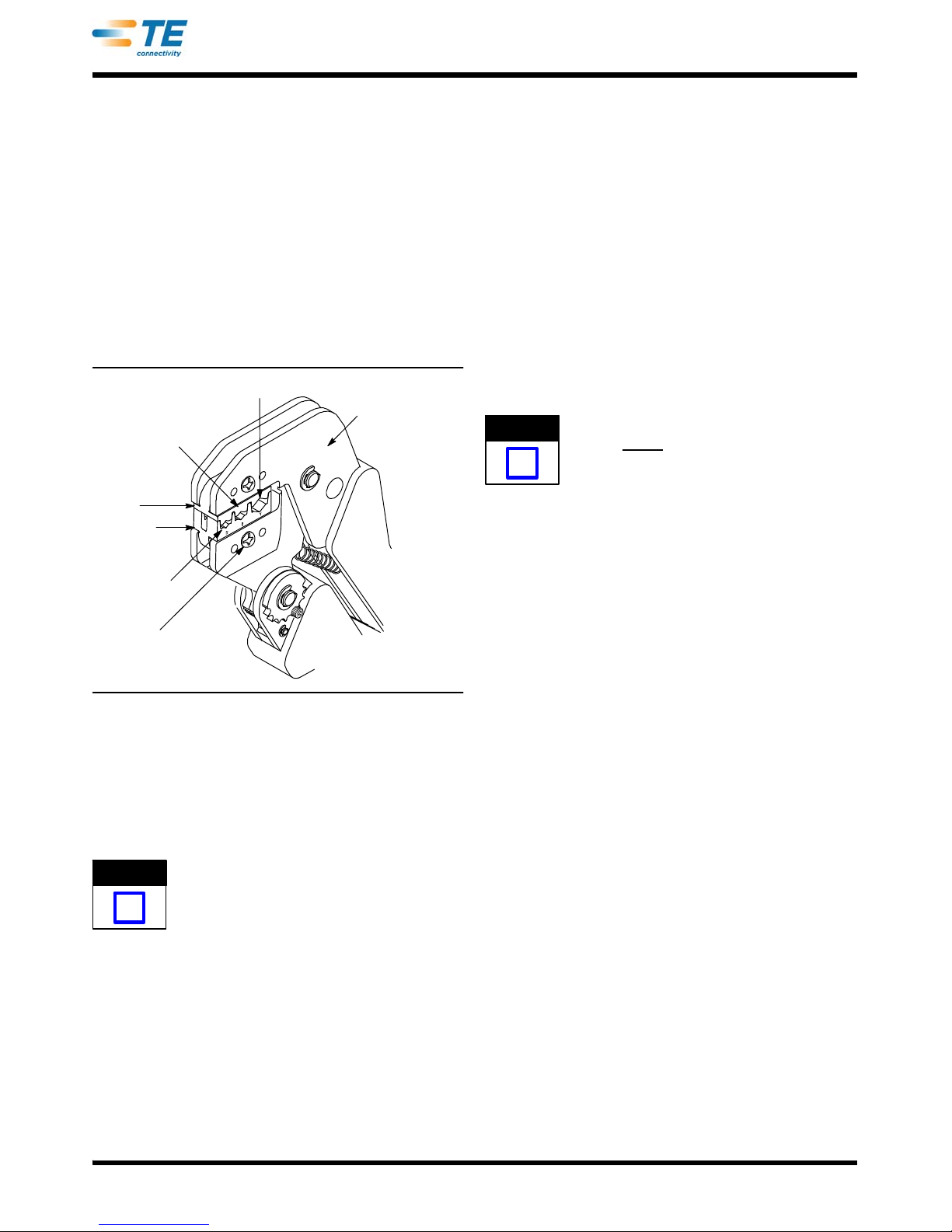
The die assembly consists of an anvil and indenter.
When closed, the dies form three crimping chambers.
The indenter is marked with the letters R, B, and Y
which correspond with the color of the terminal
insulation (red, blue, or yellow). Die retaining screws
are used to secure the dies in the tool frame. See
Figure 2.
Figure 2
Yellow
Blue
Red
Back of Tool
Die Retaining
Screw (2 Places)
Anvil
Indenter
3. INSTALLATION AND REMOVAL OF DIE ASSEMBLY
1. Close the tool handles until the ratchet releases,
then allow the handles to open fully.
The ratchet has detents that create audible clicks
as the tool handles are closed.
2. Remove the two die retaining screws and die
retaining pins (pins will not be used for this die
assembly) from the tool jaws.
3. Place the anvil in the moving jaw so that the
marked surface faces outward. Insert the die
retaining screw through the hole of the moving jaw
and hole of the anvil, and tighten the screw just
enough to hold the anvil in place. DO NOT
completely tighten the screw.
4. Place the indenter in the stationary jaw so that
the marked surface faces outward. Insert the die
retaining screw through the hole of the stationary
jaw and hole of the indenter, and tighten the screw
just enough to hold the indenter in place. DO NOT
completely tighten the screw.
5. Carefully close the tool handles, making sure
that the anvil and indenter align properly. Continue
closing the tool handles until the ratchet engages
sufficiently to hold the anvil and indenter in place,
then tighten both die retaining screws.
6. To disassemble, close the tool handles until the
ratchet releases, remove the two die retaining
screws, then slide the dies out of the tool jaws.
4. CRIMPING PROCEDURE
This tool is provided with a crimp adjustment
feature. Initially, the crimp height of a sample
terminal should be verified in accordance with
Section 5.
Refer to Figure 1, and select wire of the specified size
and insulation diameter. Strip the wire to the length
indicated in Figure 1, taking care not to nick or cut
wire strands.
Refer to Figure 3, and proceed as follows:
1. Hold the tool so that the back (wire side) is
facing you. Squeeze tool handles together and
allow them to open fully.
2. Place the terminal in the proper crimping
chamber (match color code to terminal insulation)
so that the edge of the insulation aligns with the
edge of the indenter. The wire barrel should be at
the back of the tool.
3. Hold the terminal in position, and squeeze the
tool handles together until ratchet engages
sufficiently to hold the terminal. DO NOT deform
the wire barrel.
4. Insert the stripped wire into the wire and holding
the wire in place, squeeze the tool handles
together until the ratchet releases. Allow the tool
handles to open, and remove the crimped terminal.
5. Inspect the terminal crimp height according to
Section 5.
5. CRIMP HEIGHT INSPECTION
This inspection requires the use of calipers. A lead
rod can be used to check the crimp height. Crimp a
rod in each of the crimping chambers. Check the
crimp height of the rod against the crimp height
dimension given in Figure 4.
NOTE
i
NOTE
i
408- 9252
3of 4Rev L
Figure 3
Terminal
Tongue
Edge of Terminal
Insulation Aligned
with Edge of Anvil
Stripped
Wire
Anvil
Indenter
Tool Jaws
Back of Tool
6. CRIMP HEIGHT INSPECTION
This inspection requires the use of calipers. A lead
rod can be used to check the crimp height. Crimp a
rod in each of the crimping chambers. Check the
crimp height of the rod against the crimp height
dimension given in Figure 4.
Lead Rod
Diameter
Crimping Chamber
Marking
Crimp Height
Dimension
4.8 [.19] Y (Yellow) 3.35+0.15 [.132+.006]
3.2 [.12] B (Blue) 2.44+0.15 [.096+.006]
3.2 [.12] R (Red) 2.08+0.15 [.082+.006]
Figure 4
If the crimp height conforms to the dimension, the tool
and die assembly are considered dimensionally
correct. Lubricate the tool with a thin coat of any good
SAE 20 motor oil. If it does not, adjust the crimp
height according to Section 6. If the adjustment does
not result in acceptable crimp height, the die
assembly or tool may have to be replaced.
7. RATCHET ADJUSTMENT (Figure 5)
The tool ratchet mechanism features an adjustment
wheel with numbered settings. The adjustment wheel
controls the amount of handle pressure exerted on
the jaws during crimping. Check the crimp height
according to Section 5. If the crimp height is not
acceptable, adjust the crimp height as follows:
1. Remove the lockscrew from the ratchet
adjustment wheel.
2. With a screwdriver, adjust the ratchet wheel
from the front of the tool.
3. Observe the ratchet adjustment wheel. If a
tighter (smaller) crimp height is required, rotate the
adjustment wheel counterclockwise to a
higher--numbered setting. If a looser (larger) crimp
height is required, rotate the adjustment wheel
clockwise to a lower--numbered setting.
4. Re--assemble the lockscrew.
5. Make a sample crimp. If the crimp height is
acceptable, the adjustment setting is correct. If the
crimp height is unacceptable, continue to adjust
the ratchet, and again measure a sample crimp.
Screwdriver
Lockscrew
F
i
g
u
r
e5
Ratchet Adjustment
Wheel
8. MAINTENANCE AND INSPECTION
8.1. Maintenance
Ensure that the tool frame and dies are clean by
wiping them with a clean, soft cloth. Remove any
debris with a clean, soft brush. Do not use objects
that could damage any components. When not in use,
keep tool handles closed to prevent objects from
becoming lodged in the dies, and store in a clean, dry
area.
8.2. Visual Inspection
Inspection of the dies should be made on a regular
basis to ensure that they have not become worn or
damaged. Inspect the crimping chambers for
flattened, chipped, worn, or broken areas. If damage
or abnormal wear is evident, the dies must be
replaced. Refer to Section 8, REPLACEMENT.
9. REPLACEMENT
Customer--replaceable parts are shown in Figure 1.
Available separately, Repair Kit 679221--1 includes a
replacement lock nut and a variety of pins, rings,
screws, and springs. If the dies are damaged or worn
excessively, they must be replaced. Order the repair
kit and replaceable parts through your representative,
or call 1--800--526--5142, or send a facsimile of your
purchase order to 717--986--7605, or write to:
408- 9252
Rev L4 of 4
CUSTOMER SERVICE (038--035)
TYCO ELECTRONICS CORPORATION
PO BOX 3608
HARRISBURG PA 17105--3608
10. REVISION SUMMARY
Revisions to this instruction sheet include:
SUpdated document to corporate requirements
PRO- CRIMPER III Hand Tool 354940-1
(Instruction Sheet 408-9930)
SDE-SA Hand Tool 9-1478240- 0
(Instruction Sheet 408-8851)
SDE Bench Terminator 1490076-2
(Customer Manual 409- 10052)
626 Adapter 679304-1
(Instruction Sheet 408-4070)
Battery Tool (Shouldered Die) 1725837- 1, -2
(Customer Manual 409- 10053)
Battery Tool (Pin Die) 1213890- 1, - 2
(Customer Manual 409- 10065)
Tooling Compatible with Dies 58423- 1
NOTE: RBY Splices Should
Not be Terminated in this Tool

Other TE Connectivity Power Tools manuals

TE Connectivity Micro-MaTch  528405-9 User manual

TE Connectivity

TE Connectivity Micro-MaTch 528405-9 User manual

TE Connectivity PRO-CRIMPER III User manual

TE Connectivity

TE Connectivity PRO-CRIMPER III User manual

TE Connectivity ERGOCRIMP User manual

TE Connectivity

TE Connectivity ERGOCRIMP User manual

TE Connectivity CERTILOK 9-1579022-1 User manual

TE Connectivity

TE Connectivity CERTILOK 9-1579022-1 User manual

TE Connectivity 59981-1 User manual

TE Connectivity

TE Connectivity 59981-1 User manual

TE Connectivity CBP-5T Mk II Reference guide

TE Connectivity

TE Connectivity CBP-5T Mk II Reference guide

TE Connectivity 47386-4 User manual

TE Connectivity

TE Connectivity 47386-4 User manual

TE Connectivity 2393336-1 User manual

TE Connectivity

TE Connectivity 2393336-1 User manual

TE Connectivity HPi 10 TE Instruction Manual

TE Connectivity

TE Connectivity HPi 10 TE Instruction Manual

TE Connectivity PRO-CRIMPER III User manual

TE Connectivity

TE Connectivity PRO-CRIMPER III User manual

TE Connectivity SDE-SA User manual

TE Connectivity

TE Connectivity SDE-SA User manual

TE Connectivity SOLARLOK User manual

TE Connectivity

TE Connectivity SOLARLOK User manual

TE Connectivity 2844990-1 Reference guide

TE Connectivity

TE Connectivity 2844990-1 Reference guide

TE Connectivity SDE-SA User manual

TE Connectivity

TE Connectivity SDE-SA User manual

TE Connectivity 2031676-1 User manual

TE Connectivity

TE Connectivity 2031676-1 User manual

TE Connectivity 408-160034 User manual

TE Connectivity

TE Connectivity 408-160034 User manual

TE Connectivity CAPI-6T User manual

TE Connectivity

TE Connectivity CAPI-6T User manual

TE Connectivity 2217074-1 User manual

TE Connectivity

TE Connectivity 2217074-1 User manual

TE Connectivity 2396645-1 User manual

TE Connectivity

TE Connectivity 2396645-1 User manual

TE Connectivity 539 666-2 User manual

TE Connectivity

TE Connectivity 539 666-2 User manual

TE Connectivity 1976330-1 User manual

TE Connectivity

TE Connectivity 1976330-1 User manual

TE Connectivity ERGOCRIMP 7-1579004-1 User manual

TE Connectivity

TE Connectivity ERGOCRIMP 7-1579004-1 User manual

TE Connectivity 2405856-1 User manual

TE Connectivity

TE Connectivity 2405856-1 User manual

TE Connectivity PRO- CRIMPER III User manual

TE Connectivity

TE Connectivity PRO- CRIMPER III User manual

Popular Power Tools manuals by other brands

Hitachi H 65 instruction manual

Hitachi

Hitachi H 65 instruction manual

TYROLIT Hydrostress / DME24UW Series operating instructions

TYROLIT Hydrostress

TYROLIT Hydrostress / DME24UW Series operating instructions

Sealey POWER TOOLS SNA9821 instructions

Sealey

Sealey POWER TOOLS SNA9821 instructions

hawa Alcu-Press 2605 Original operating instructions

hawa

hawa Alcu-Press 2605 Original operating instructions

909 HG2000 instruction manual

909

909 HG2000 instruction manual

ULTIMATE SPEED KH 4055 EXTENDABLE WHEEL WRENCH manual

ULTIMATE SPEED

ULTIMATE SPEED KH 4055 EXTENDABLE WHEEL WRENCH manual

Arrow T50DCD user manual

Arrow

Arrow T50DCD user manual

Leister Diode S operating instructions

Leister

Leister Diode S operating instructions

Bosch 1775E - 5" 8.5 Amp Tuckpoint Grinder Operating/safety instructions

Bosch

Bosch 1775E - 5" 8.5 Amp Tuckpoint Grinder Operating/safety instructions

Craftex CX817N user manual

Craftex

Craftex CX817N user manual

Erbauer ERB150D instruction manual

Erbauer

Erbauer ERB150D instruction manual

Desoutter PT110-T4500-I13S user manual

Desoutter

Desoutter PT110-T4500-I13S user manual

Clarke 6505512 Operation & maintenance instructions

Clarke

Clarke 6505512 Operation & maintenance instructions

KTC GLK Series instruction manual

KTC

KTC GLK Series instruction manual

Mercury 710.350UK user manual

Mercury

Mercury 710.350UK user manual

STEINEL HL 1620 S Translation of the original operating instructions

STEINEL

STEINEL HL 1620 S Translation of the original operating instructions

Intelitek SCORA-ER 14 user manual

Intelitek

Intelitek SCORA-ER 14 user manual

Makita AN942 instruction manual

Makita

Makita AN942 instruction manual

manuals.online logo
manuals.online logoBrands
  • About & Mission
  • Contact us
  • Privacy Policy
  • Terms and Conditions

Copyright 2025 Manuals.Online. All Rights Reserved.