TE Connectivity T2212 User manual

Operator's Manual
T2212 PRINTER

2 2
Type
T2212-PRINTER
T2212-SWARE-PRINTER
Doc. # 412-121037 revision 1
Copyright
This documentation as well as translation hereof are property
of TE Connectivity.
The replication, conversion, duplication or divulgement of the
whole manual or parts of it for other intentions than its original
intended purpose demand the previous written authorization
by TE Connectivity.
Trademark
Windows is a registered trademark of the Microsoft
Corporation.
Editor
Regarding questions or comments please contact TE
Connectivity.
Topicality
Due to the constant further development of our products
discrepancies between documentation and products can
occur.
Please check with your local TE Connectivity Representative
for the latest update.
Operator's Manual
for the following products
For technical support please download TE document 411-121057. Alternatively: Technical Support

3
1 Introduction ............................................................................................................................................ 4
1.1 Instructions............................................................................................................................................... 4
1.2 Intended Use............................................................................................................................................ 4
1.3 Safety Instructions.................................................................................................................................... 5
1.4 Environment ............................................................................................................................................. 5
2 Installation .............................................................................................................................................. 6
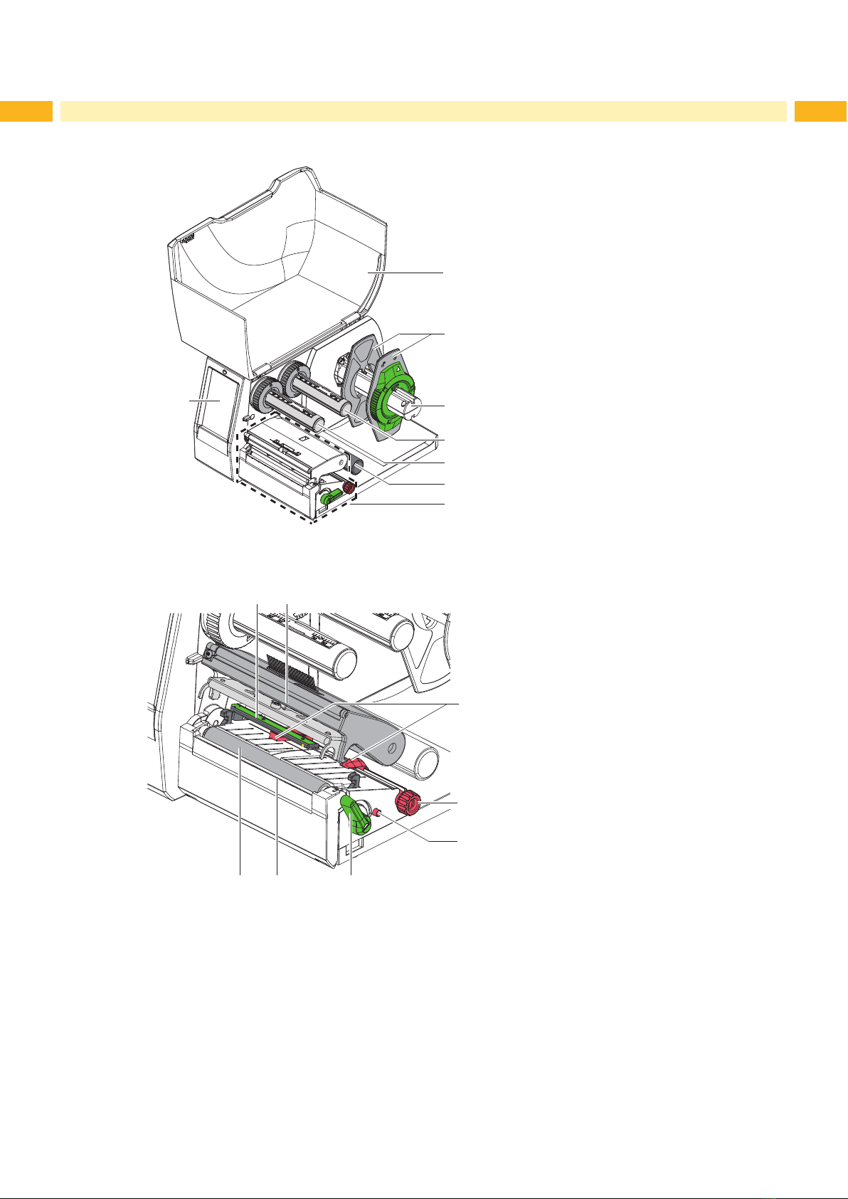
2.1 Device Overview ...................................................................................................................................... 6
2.2 Unpacking and Setting-up the Printer ...................................................................................................... 8
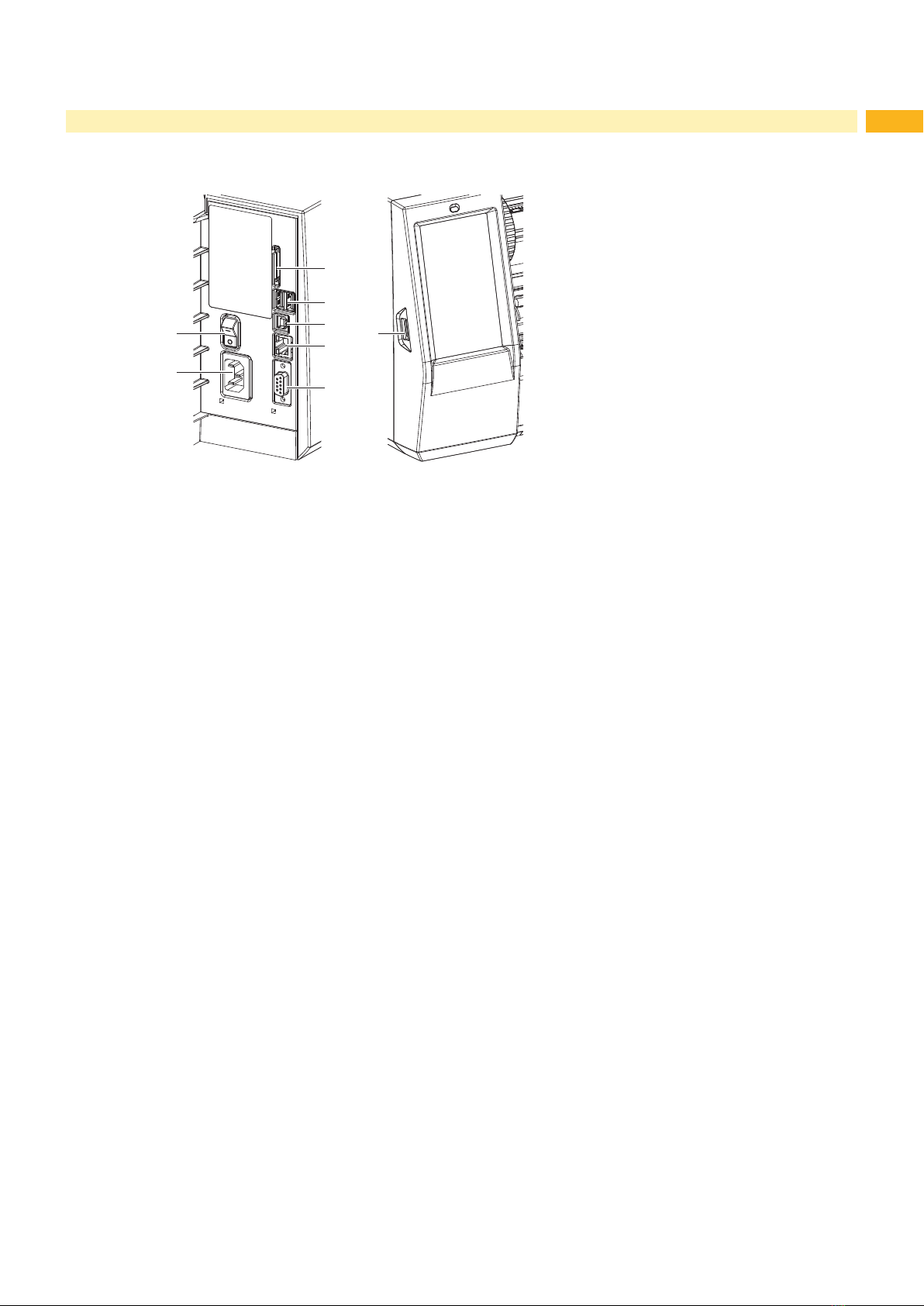
2.3 Connecting the Device ............................................................................................................................. 8
2.3.1 Connecting to the Power Supply ........................................................................................................ 8
2.3.2 Connecting to a Computer or Computer Network .............................................................................. 8
2.4 Switching on the Device........................................................................................................................... 8
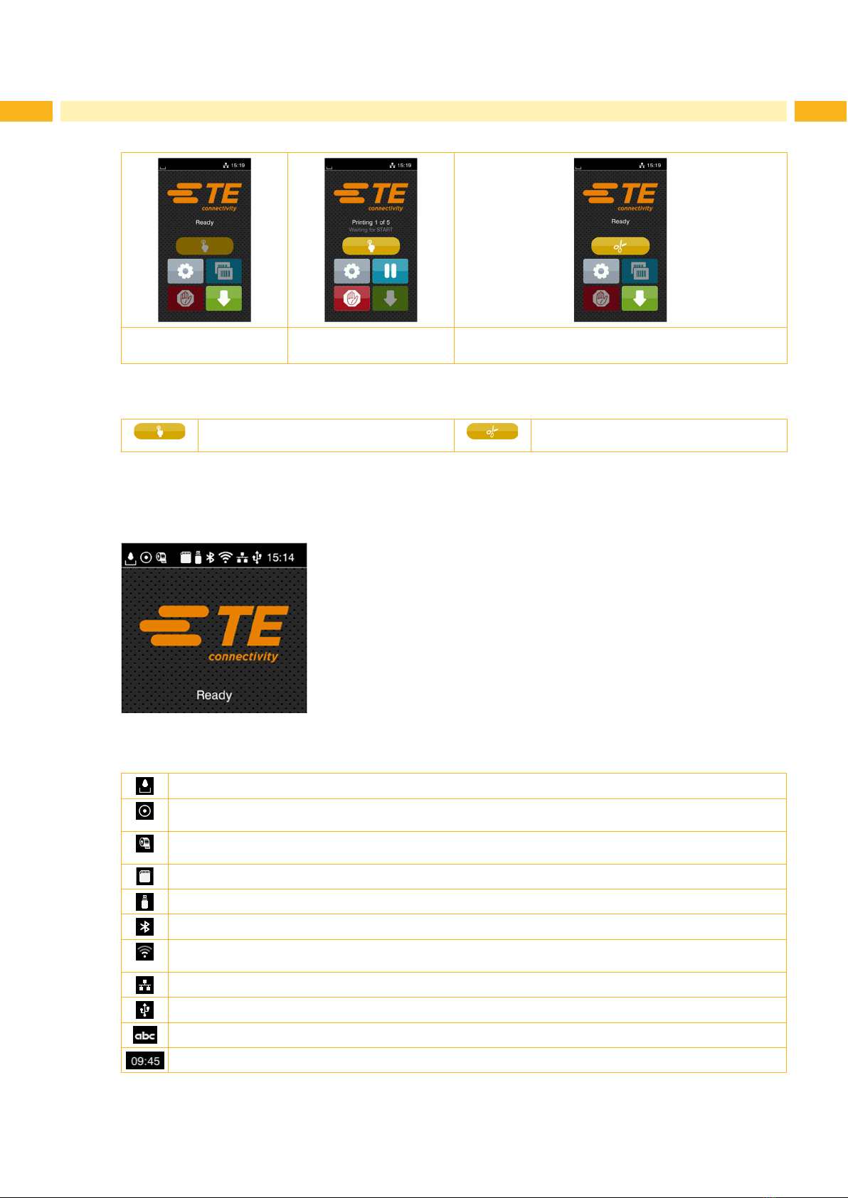
3 Touchscreen-Display ............................................................................................................................. 9
3.1 Start Screen ............................................................................................................................................. 9
3.2 Navigation in the Menu ...........................................................................................................................11
4 Loading Material................................................................................................................................... 12
4.1 Loading Media from a Roll ..................................................................................................................... 12
4.2 Adjusting the Label Sensor .................................................................................................................... 13
4.3 Loading Transfer Ribbon........................................................................................................................ 14
4.4 Setting the Feed Path of the Transfer Ribbon........................................................................................ 15
5 Printing Operation................................................................................................................................ 16
5.1 Printing in Tear-off Mode ........................................................................................................................ 16
5.2 Printing in Cutting Mode......................................................................................................................... 16
6 Cleaning ................................................................................................................................................ 17
6.1 Cleaning Information .............................................................................................................................. 17
6.2 Cleaning the Print Roller ........................................................................................................................ 17
6.3 Cleaning the Printhead........................................................................................................................... 18
7 Fault Correction ................................................................................................................................... 19
7.1 Error Display .......................................................................................................................................... 19
7.2 Error Messages and Fault Correction .................................................................................................... 19
7.3 Problem Solution.................................................................................................................................... 21
8 Licenses................................................................................................................................................ 22
8.1 Reference to the EU Declaration of Conformity ..................................................................................... 22
8.2 FCC........................................................................................................................................................ 22
9 Index...................................................................................................................................................... 23
Table of Contents

4 4
1 Introduction
1.1 Instructions
Important information and instructions in this documentation are designated as follows:
Danger!
Draws attention to an exceptionally grave, imminent danger to your health or life due to hazardous
voltages.
!
Danger!
Draws attention to a danger with high risk which, if not avoided, may result in death or serious injury.
!
Caution!
Draws attention to a danger with low risk which, if not avoided, may result in minor or moderate injury.
!
Attention!
Draws attention to potential risks of property damage or loss of quality.
i
Note!
Advices to make work routine easier or on important steps to be carried out.
Environment!
Gives you tips on protecting the environment.
Handling instruction
Reference to section, position, illustration number or document.
Option (accessories, peripheral equipment, special ttings).
Time Information in the display.
1.2 Intended Use
• The device is manufactured in accordance with the current technological status and the recognized safety rules.
However, danger to the life and limb of the user or third parties and/or damage to the device and other tangible
assets can arise during use.
• The device may only be used for its intended purpose and if it is in perfect working order, and it must be used with
regard to safety and dangers as stated in the operating manual.
• The device printer is intended exclusively for printing suitable materials that have been approved by the manufac-
turer. Any other use or use going beyond this shall be regarded as improper use. The manufacturer/supplier shall
not be liable for damage resulting from unauthorized use; the user shall bear the risk alone.
• Usage for the intended purpose also includes complying with the operating manual, including the manufacturer‘s
maintenance recommendations and specications.
i
Note!
Further documentation are included on the DVD enclosed in the printer box, and can be found on
www.te.com/identication.

5
1 Introduction
1.3 Safety Instructions
• The device is congured for voltages of 100 to 240 V AC. It only has to be plugged into a grounded socket.
• Only connect the device to other devices which have a protective low voltage.
• Switch off all affected devices (computer, printer, accessories) before connecting or disconnecting.
• The device may only be used in a dry environment, do not expose it to moisture (sprays of water, mists, etc.).
• Do not use the device in an explosive atmosphere.
• Do not use the device close to high-voltage power lines.
• If the device is operated with the cover open, ensure that people‘s clothing, hair, jewelry etc. does not come into
contact with the exposed rotating parts.
• The device or parts of it can become hot while printing. Do not touch during operation, and allow it to cool down
before changing material and before disassembly.
• Risk of crushing limbs and/or ngers when closing the cover. Only touch the cover on the outside. Do not reach
into the swivel range of the cover.
• Perform only those actions described in this operating manual.
Work going beyond this may only be performed by trained personnel or service technicians.
• Unauthorized interference with electronic modules or their software can cause malfunctions.
• Other unauthorized work on, or modications to, the device can also endanger operational safety.
• Always have service work done by a qualied workshop, where the personnel have the technical knowledge and
tools required to do the necessary work.
• There are various warning stickers on the device. They draw your attention to danger.
Warning stickers may therefore not be removed, because you and other people will not be made aware of
pending dangers and may be injured.
• The maximum noise level is under 0.063 Pa/70 dB(A).
Danger!
Danger to life and limb from the power supply.
Do not open the device casing.
!
Warning!
This is a class A product. In a domestic environment this product may cause radio interference in which
case the user may be required to take adequate measures.
1.4 Environment
Obsolete devices contain valuable recyclable materials that should be sent for recycling.
Send to suitable collection points, separately from residual waste.
The modular construction of the printer enables it to be easily disassembled into its component parts.
Send the parts for recycling.
The electronic circuit board of the device is equipped with a lithium battery.
Take old batteries to collection boxes in shops or public waste disposal centres.

6 6
2 Installation
2.1 Device Overview
1
2
3
4
5
6
7
8
1 Cover
2 Margin stop
3 Roll retainer
4 Ribbon supply hub
5 Ribbon take-up hub
6 Roller
7 Print unit
8 Touchscreen-Display
Figure 1 Overview
12
14
11
9 10
1516
13
9 Label sensor
10 Printhead retainer with printhead
11 Guides
12 Knob for adjusting the guides
13 Knob for adjusting the label sensor
14 Lever for locking the printhead
15 Tear-off plate
16 Print roller
Figure 2 Print unit

7
17
18
21
19
20
23
22 24
17 Power switch
18 Power connection jack
19 Slot for SD card
20 2 USB master ports for keyboard,
scanner, USB memory stick, Bluetooth
adapter, service key or WiFi stick
21 USB full-speed slave port
22 Ethernet 10/100 Base-T
23 Serial RS-232 port
24 USB master port for service key or USB
memory stick
Figure 3 Connections
2 Installation

8 8
2 Installation
2.2 Unpacking and Setting-up the Printer
Lift the label printer out of the box.
Check label printer for damage which may have occurred during transport.
Set up printer on a level surface.
Remove foam transportation safeguards near the printhead.
Check delivery for completeness.
Contents of delivery:
• T2212-PRINTER
• Power cables
• USB cable
• Operator's Manual
• DVD with Windows driver and documentation
i
Note!
Please keep the original packaging in case the printer must be returned.
In the event a printer is returned please ensure all printing materials are removed from the printer before
shipping.
!
Attention!
The device and printing materials will be damaged by moisture.
Set up label printers only in dry locations protected from moisture.
2.3 Connecting the Device
The standard available interfaces and connectors are shown in Figure 3.
2.3.1 Connecting to the Power Supply
The printer is equipped with a wide area power unit. The device can be operated with a supply voltage of
100-240 V~/50-60 Hz without adjustment.
1. Check that the device is switched off.
2. Plug the power cable into the power connection socket (18/Figure 3).
3. Plug the power cable into a grounded socket.
2.3.2 Connecting to a Computer or Computer Network
!
Attention!
Inadequate or no grounding can cause malfunctions during operations.
Ensure that all computers and cables connected to the label printer are grounded.
Connect the printer to a computer or network with a suitable cable.
To connect the printer please consult the Quick start guide (TE document 411-121061) found in the cover of the
Printer CD case.
2.4 Switching on the Device
When all connections have been made:
Switch the printer on at the power switch (17/Figure 3).
The printer performs a system test, and then shows the system status Ready in the display.

9
3 Touchscreen-Display
The user can control the operation of the printer with the control panel, for example:
• Issuing, interrupting, continuing and canceling print jobs,
• Setting printing parameters, e.g. heat level of the printhead, print speed, interface conguration, language and
time of day.
• Control stand-alone operation with a memory module.
• Update the rmware..
Many functions and settings can also be controlled by software applications or by direct programming with a
computer using the printer’s own commands.
Settings made on the touchscreen display set the basic settings of the printer.
i
Note!
It is advantageous, whenever possible, to make adjustments to various print jobs in the software.
3.1 Start Screen
After switching on During printing In pause state After print job
Figure 4 Start screen
The touchscreen display is operated by touch:
• To open a menu or select a menu item lightly touch the corresponding symbol.
• To scroll in lists slide nger up or down on the display.
Open the menu Repeat the last printed label
Interrupt the print job Cancel all print jobs
Continue the print job Feed a blank label
Table 1 Symbols on the start screen
i
Note!
Inactive symbols are shaded.

10 10
With special software or hardware congurations additional symbols appear on the start screen:
Printing on demand
without print job
Printing on demand
within print job
Direct cut
with cutter or perforator installed (accessory)
Figure 5 Optional symbols on the start screen
Initiate the printing of a single label within a
print job including cutting, perforating...
Release a direct cut without media feed
Table 2 Optional symbols on the start screen
Depending on the conguration a range of information is visible via several icons in the status bar:
Figure 6 Icons of the status bar
Displays the current data transfer in the form of a falling drop.
The Save data stream function is active
All received data are stored in a .lbl le.
Warning ribbon end
The remaining ribbon is below the required amount
SD card installed
USB memory installed
Gray: Bluetooth adapter installed, White: Bluetooth connection active
WiFi connection active
The WiFi strength is displayed by the number of white arcs.
Ethernet connection active
USB connection active
abc program active
Clock time
Table 3 Icons on the status bar
3 Touchscreen-Display

11
3.2 Navigation in the Menu
Start level Selection level Parameter/function level
Figure 7 Menu levels
To open the menu select on the start screen.
Select a theme in the selection level.
Several themes have substructures again with selection levels.
To return from the current level to the upper one select . To leave the menu select .
Continue the selection until the parameter/function level is reached.
Select function. The printer may perform a function after a preparatory dialog, if necessary.
- or -
Select parameter. The setting options depend on the type of parameter.
Logical parameters Selection parameters Numerical parameters Date/time
Figure 8 Samples for parameter setting
Scroll bar for rough value setting
Decreasing the value step-by-step
Increasing the value step-by-step
Return without saving the setting
Return and save settings
Parameter is disabled, touching enables the parameter
Parameter is enabled, touching disables the parameter
Table 4 Buttons for setting parameters
3 Touchscreen-Display

12 12
4 Loading Material
4.1 Loading Media from a Roll
5
7
8
6
9
2
1
3
4
Figure 9 Loading media from a roll
1. Open cover.
2. Turn ring (2) of the margin stop (1) counterclockwise, so that the arrow points to the symbol , and thus release
the margin stop.
3. Remove the margin stop (1) from the roll retainer (4).
4. Load label roll (3) on the roll retainer (4) in such a way that the labels can be inserted into the printhead in the
correct position. The printable side of the labels must be visible from above.
5. Re-mount the margin stop (1) onto the roll retainer (4). Push the margin stop (1) to the roll (3) until the roll touches
both margin stops and a clear resistance is encountered.
6. Turn ring (2) clockwise, so that the arrow points to the symbol , and thus x the margin stop (1) on the roll
retainer (4).
7. Turn lever (8) counterclockwise to open printhead.
8. Position guides (5) by turning the knob (7) so that they are several millimeters wider than the material.
9. Position material below the roller (6) and guide it through the print unit.
!
Attention!
Guide material through the print unit below the label sensor (9).
10. Move guides (5) close to the edges of the material without clamping the material.
11. Adjust label sensor (4.2 on page 13).
12. Press printhead retainer down and turn lever (8) clockwise to lock the printhead.

13
4.2 Adjusting the Label Sensor
i
Note!
When the printer is delivered the label sensor is positioned in the middle of the paper feed. Thus, the label
sensor must only be adjusted if materials with the following characteristics are used:
• Material with reex or cut-out marks, which are not in the middle.
• Multi-column material with an even number of columns.
• Material with irregularly shaped labels.
1 2
3a
3b
Figure 10 Adjusting the label sensor
The sensor position (2) is marked with a yellow LED in the sensor holder.
1. Open the printhead.
2. Release the label sensor (3) by pressing, so that it is extended (3b) ready to make an adjustment.
3. Position the sensor holder (1) by turning the knob (3) so that the sensor (2) can detect the front edge of the label
in the direction of paper ow or the reex or cut-out mark.
4. Return the label sensor adjuster knob by pushing it back in (3a)
i
Note!
It is important to ensure the label sensor adjustment knob is returned into the printer (3a), before closing
the printhead.
4 Loading Material

14 14
4.3 Loading Transfer Ribbon
C
A
B
1
1
6
12 3 4 5
Figure 11 Guide Adjustment Figure 12 Loading Transfer Ribbon
1. Open the printhead.
2. Clean the printhead before loading the transfer ribbon (6.3 on page 18).
3. Set guide (1) on the ribbon supply hub to the correct transfer ribbon width (Figure 11):
• Hold the hub and unlock the guide (1) by turning it in direction A.
• Slide the guide in direction B and adjust the guide to the ribbon width using the scale.
• Hold the hub and lock the guide by turning it in direction C.
4. Slide transfer ribbon roll (5) onto the ribbon supply hub (3) until it reaches the guide (1) so that the ink coating of
the ribbon faces downward when being unwound.
i
Note!
To rewind the ribbon a ribbon core (4) is needed that must be at least equal in width to the supply ribbon.
When changing the transfer ribbon use the empty supply ribbon core for winding the next ribbon.
5. Adjust the position of the guide on the take-up hub to the width of the ribbon core (4) and push ribbon core on the
take-up hub (2).
6. Guide the transfer ribbon though the printing unit as shown in Figure 13.
!
Attention!
Guide transfer ribbon over the label sensor (6).
7. Secure the starting end of transfer ribbon to the transfer ribbon core (4) with adhesive tape. The transfer ribbon
take-up hub is turned counterclockwise.
8. Turn transfer ribbon take-up hub (2) counterclockwise to smooth out the feed path of the transfer ribbon.
9. Close the printhead.
Figure 13 Transfer Ribbon Feed Path
4 Loading Material

15
4.4 Setting the Feed Path of the Transfer Ribbon
Transfer ribbon wrinkling can lead to print image errors. The transfer ribbon deection bar (2) can be adjusted to
prevent wrinkles.
1 2
Figure 14 Setting the feed path of the transfer ribbon
i
Note!
The adjustment is best carried out during printing.
Turn screw (1) with torx wrench TX10 and observe the behavior of the ribbon.
• By turning it clockwise the outer edge of the transfer ribbon is tightened.
• By turning it counterclockwise the inner edge of the transfer ribbon is tightened.
4 Loading Material

16 16
5 Printing Operation
!
Attention!
Printhead damage is caused by improper handling!
Do not touch the underside of the printhead with ngers or sharp objects.
Ensure labels are clean.
Ensure that the label surfaces are smooth. Rough labels act like emery paper and reduce the service life
of the printhead.
Print with the lowest possible printhead temperature.
The Printer is ready for operation when all connections are made and the transfer ribbon and labels are loaded.
5.1 Printing in Tear-off Mode
After printing, a label can be torn off manually using the tear off plate (2) Figure 15.
5.2 Printing in Cutting Mode
Cutter and Perforator units are available as an accessory. Please consult TE document TTDS-260 for all TE printer
accessories.

17
6 Cleaning
6.1 Cleaning Information
Danger!
Risk of death via electric shock!
Disconnect the printer from the power supply before performing any maintenance work.
The label printer requires very little maintenance.
It is important to clean the thermal printhead regularly. This guarantees a consistently good printed image and plays a
major part in preventing premature wear of the printhead.
Otherwise, the maintenance is limited to monthly cleaning of the device.
!
Attention!
The printer can be damaged by aggressive cleansers.
Do not use abrasive cleaners or solvents for cleaning the external surfaces or modules.
Remove dust and paper uff from the print area with a soft brush or vacuum cleaner.
6.2 Cleaning the Print Roller
Accumulations of dirt on the print roller may impair the media transport and the print quality.
!
Attention!
Damage of the print roller.
Do not use sharp objects (knives, screwdrivers, etc.) to clean the print roller.
4
31 12
Figure 15 Print roller
1. Open the printhead.
2. Remove material and transfer ribbon from the printer.
3. Fold down the tear-off plate (2).
4. Lift the print roller (3) from its retainers (1).
5. Remove deposits with roller cleaner and a soft cloth, or replace it if the roller appears damaged.
6. Push roller with bearings (4) into the retainers (1) until they click into place.
7. Fold up the tear-off plate (2).

18 18
6.3 Cleaning the Printhead
Cleaning intervals: - every media roll change
Substances may accumulate on the printhead during printing and adversely affect printing, e.g. differences in contrast
or vertical stripes.
!
Attention!
Printhead can be damaged!
Do not use sharp or hard objects to clean the printhead.
Do not touch protective glass layer of the printhead.
!
Caution!
Risk of injury from the hot printhead.
Ensure that the printhead has cooled down before starting cleaning.
1
Figure 16 Heating line of the printhead
Open the printhead.
Remove material and transfer ribbon from the printer.
Clean the printhead heating line (1) with Alcohol (IPA) and a soft cloth.
(For detailed information and advice please consult TE document 411-121037 Thermal Transfer printhead
cleaning instructions.)
Allow printhead to dry for 2–3 minutes before commencing printing.
6 Cleaning

19
7 Fault Correction
7.1 Error Display
The appearance of an error will be shown on the display:
Figure 17 Error display
The error correction is dependent on the error type 7.2 on page 19.
The display offers the following solutions to continue printing.
Repeat The print job will continue after clearing the error.
Cancel The print job will be cancelled.
Feed The paper feed will be synchronized. Following the print job can be continued.
Ignore The error message will be ignored. The print job will be continued possibly with limited
performance.
Save log The error does not allow print operation.
For detailed analysis several system les can be saved on an external memory.
Table 5 Button in the error display
7.2 Error Messages and Fault Correction
Error message Cause Remedy
Barcode error Invalid barcode content, e.g. alphanumeric
characters in a numerical barcode
Correct the barcode content.
Barcode too big The barcode is too big for the allocated
area of the label
Reduce the size of the barcode or move it.
Buffer overow The input buffer memory is full and the
computer is still transmitting data.
Use data transmission via protocol (preferably
RTS/CTS).
Cutter blocked Cutter cannot return into its home position
and stays in an undened position
Switch off the printer. Remove material. Switch on
the printer. Restart print job.
Change material
No cutter function Switch the printer off and then on.
If error recurs call service.
Cutter jammed The cutter is unable to cut the labels but is
able to return into its home position
Press Cancel
Change material.
Device not conn. Programming addresses a non-existent
device
Either connect this device or correct the
programming.
File not found Requested le is not on the card Check the contents of the card.
Font not found Error with the selected download font Cancel current print job, change font.
Memory overow Current print job contains too much infor-
mation, e.g. selected font, large graphics
Cancel current print job.
Reduce amount of data to be printed.
Name exists Duplicate usage of eld name in the direct
programming
Correct programming

20 20
7 Fault Correction
Error message Cause Remedy
No label found There are labels missing on the label
material
Press Repeat repeatedly until printer recognizes the
next label on the material.
The label format as set in the software
does not correspond with the real label
format
Cancel current print job.
Change the label format set in the software.
Restart print job.
Printer is loaded with continuous paper, but
the software is set on labels
Cancel current print job.
Change the label format set in the software.
Restart the print job.
No label size The size of the label is not dened in the
programming.
Check programming.
Out of paper Out of label roll Load labels.
Error in the paper feed Check paper feed.
Out of ribbon Out of transfer ribbon Load new transfer ribbon.
Transfer ribbon melted/snapped during
printing
Cancel current print job.
Change the heat level via software.
Clean the printhead 6.3 on page 18
Load transfer ribbon.
Restart print job.
Printhead open Printhead not locked Lock printhead.
Printhead too hot Printhead is overheated After pausing the print job will be continued
automatically. If the fault recurs repeatedly, reduce
the heat level or the print speed via software.
Read error Read error when reading from the memory
card
Check data of the card.
Backup data, reformat card.
Remove ribbon Transfer ribbon is loaded although the
printer is set to direct thermal printing
Set the printer in the conguration or in the
software to transfer printing
Ribbon ink side Identied ribbon unwinding direction does
not match to the setup setting
Ribbon loaded incorrectly.
Clean the printhead 6.3 on page 18.
Load the ribbon correctly.
Setting does not match to the used ribbon.
Correct the setting.
Syntax error Printer has received an unknown or invalid
command from the computer.
Press Ignore to skip the command or
press Cancel to cancel the print job.
Unknown card Card not formatted,
Type of card not supported
Format card, use different type of card.
Voltage error Hardware error Switch the printer off and then on.
If error recurs contact TE Technical support.
It is shown which voltage has failed. Please note.
Write error Hardware error Repeat the write process, reformat card.
Table 6 Error Messages and Fault Correction
Other manuals for T2212
3
Table of contents
Other TE Connectivity Printer manuals

TE Connectivity
TE Connectivity T6112DS Manual

TE Connectivity
TE Connectivity T6112DS User manual

TE Connectivity
TE Connectivity HTP600 Troubleshooting guide

TE Connectivity
TE Connectivity BTT-02 User manual

TE Connectivity
TE Connectivity T3212 User manual

TE Connectivity
TE Connectivity T3212 User manual

TE Connectivity
TE Connectivity T2212 User manual

TE Connectivity
TE Connectivity T2212 User manual

TE Connectivity
TE Connectivity T3200 Guide

TE Connectivity
TE Connectivity T3212 User manual