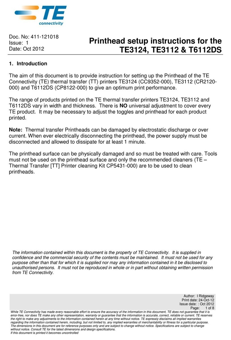
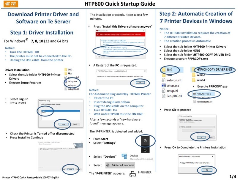
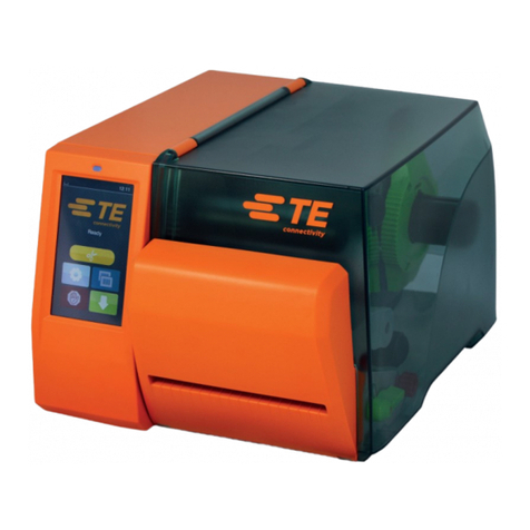
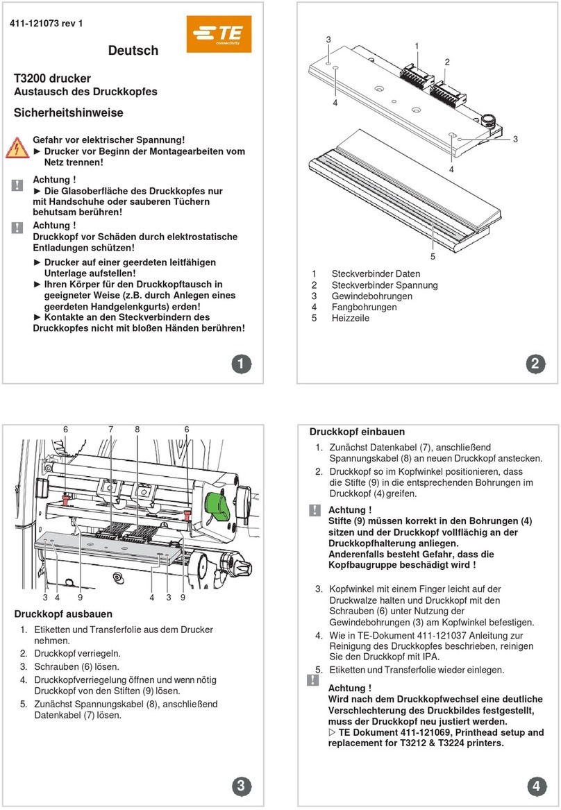
TE Connectivity T3212 User manual

5375 (08/13)
411-121069 INSTRUCTION
CLASS 1- Public
© 2018 TE Connectivity Ltd. family of companies.
All Rights Reserved.
| Indicates Change
TE Proprietary & Confidential Information
Class I Data Classification - See Policy TEC-02-04 1 of 13
Rev [1]
30 May 2018
PRINTHEAD SETUP AND REPLACEMENT
FOR T3212 & T3224 PRINTERS
THIS IS A CLASS 1 DOCUMENT WHICH IS NONCONFIDENTIAL.
The information contained within this document is the property of TE Connectivity. It is supplied in
confidence and the commercial security of the contents must be maintained. It must not be used for any
purpose other than that for which it is supplied nor may any information contained in it be disclosed to
unauthorised persons. It must not be reproduced in whole or in part without obtaining written permission
from TE Connectivity (TE).
While TE has made every reasonable effort to ensure the accuracy of the information in this catalog, TE does not guarantee that it is error-free, nor does TE make any
other representation, warranty or guarantee that the information is accurate, correct, reliable or current. TE reserves the right to make any adjustments to the information
contained herein at any time without notice. TE expressly disclaims all implied warranties regarding the information contained herein, including, but not limited to, any
implied warranties of merchantability or fitness for a particular purpose. The dimensionsin this catalog are for reference purposes only and are subject to change without
notice. Specifications are subject to change without notice. Consult TE for the latest dimensions and design specifications.
*Trademark. TE Connectivity, TE connectivity (logo), and TE (logo) are trademarks. Other logos, product and/or company names may be trademarks of their respective owners.

5375 (08/13)
411-121069 INSTRUCTION
CLASS 1- Public
© 2018 TE Connectivity Ltd. family of companies.
All Rights Reserved.
| Indicates Change
TE Proprietary & Confidential Information
Class I Data Classification - See Policy TEC-02-04 2 of 13
Rev [1]
30 May 2018
Table of Contents
1.
INTRODUCTION..............................................................................................................................3
1.1.
Safety............................................................................................................................................3
2.
PRINTHEAD TESTS......................................................................................................................4
2.1.
Test grid printout examples...............................................................................................5
3.
PRINTHEAD SETUP.....................................................................................................................6
3.1.
Preparing the printer for adjustment.............................................................................6
4.
PRINTHEAD ALIGNMENT.........................................................................................................7
4.1.
Adjusting the printhead position......................................................................................7
5.
PRINTHEAD PRESSURE...........................................................................................................8
5.1.
Adjusting the printhead pressure....................................................................................8
6.
TRANSFER RIBBON ADJUSTMENTS...............................................................................9
6.1.
Adjusting the transfer ribbon feed path.......................................................................9
7.
REPLACING THE PRINTHEAD...........................................................................................10
8.
REPLACING THE DRIVE ROLLER....................................................................................12
9.
ORDER DETAILS AND RELATED TE DOCUMENTS.............................................13
9.1.
Related parts order details..............................................................................................13
9.2.
Related TE documents.....................................................................................................13

5375 (08/13)
411-121069 INSTRUCTION
CLASS 1- Public
© 2018 TE Connectivity Ltd. family of companies.
All Rights Reserved.
| Indicates Change
TE Proprietary & Confidential Information
Class I Data Classification - See Policy TEC-02-04 3 of 13
Rev [1]
30 May 2018
1. INTRODUCTION
All TE Connectivity (TE), printers are optimised for a wide range of printable TE media with
different print surfaces, thickness and formats.
It is sometimes necessary to make small adjustments to the printer and software to give an
acceptable print contrast.
The following print quality imperfections may indicate the necessity to adjust the print mechanism:
Print image is too light.
Print image is spotty.
Print image is lighter on one side.
Horizontal printed lines are not parallel to the horizontal label edges.
Clear lateral drift of the transfer ribbon (ribbon crease).
Note!
Before making any adjustments to the print mechanism, ensure that the surfaces to be printed on,
are clean and free of dust and debris, and that the drive roller is in good condition.
Print image defects can also arise from wrinkling transfer ribbon.
Always check the transfer ribbon the feed path is correct before making any print mechanism
adjustment. Ensure the recommended transfer ribbon combination is being used by checking TE
document 411-121005, Identification Printer Product Ribbon Matrix.
1.1. Safety
Whenever working on a printer for repair or maintenance, always ensure that the printer
is switched off and disconnected from its power source.
Allow a minimum of two minutes to elapse for any stored capacitive energy to discharge.
When changing any electrostatic-sensitive devices, ensure electrostatic discharge
precautions are taken.
Always follow local safety rules.
Always use the correct tool for each job.
TE recommend that maintenance and repair of printers, is carried out by a qualified engineer. For
contact details of your regional TE Technical Support Engineer, please use the following link:
Technical Support

5375 (08/13)
411-121069 INSTRUCTION
CLASS 1- Public
© 2018 TE Connectivity Ltd. family of companies.
All Rights Reserved.
| Indicates Change
TE Proprietary & Confidential Information
Class I Data Classification - See Policy TEC-02-04 4 of 13
Rev [1]
30 May 2018
2. PRINTHEAD TESTS
If the quality of printing is bellow standard, it is recommended to carry
out printer tests before commencing with any adjustments.
For all printer tests, load a roll of labels or continuous paper 106mm
wide, together with the appropriate ribbon.
With the printer powered up showing the “Ready” screen, select the
“Setup” Icon.
In the “Setup” screen, select “Test”.
Within the “Test” menu there are two printer tests, that can help
diagnosing the print quality and the state of the Printhead.
In the “Test” menu select “Status Print” this is particularly useful when
conveying information to TE Technical support.
To check printhead health and Horizontal alignment, select “Test Grid”
and initiate the print.
Print outs are stopped b
y
selectin
g
cancel.
Printer Menu Icons
“Set up”
”Test”
”Status Print”
“Test Grid”
“Cancel”

5375 (08/13)
411-121069 INSTRUCTION
CLASS 1- Public
© 2018 TE Connectivity Ltd. family of companies.
All Rights Reserved.
| Indicates Change
TE Proprietary & Confidential Information
Class I Data Classification - See Policy TEC-02-04 5 of 13
Rev [1]
30 May 2018
2.1. Test grid printout examples
Figure 1, healthy printhead. Figure 2, ribbon crease.
Figure 3, damaged printhead. Figure 4, worn roller.
Figure 1, is an example of a healthy printhead, with no need for any printhead adjustment, please
check product and ribbon.
Figure 2, shows evidence of ribbon crease please go to section 6.
Figure 3, exhibits evidence of printhead damage. Clean print head rigorously and retest.
(“Thermal Transfer Printhead cleaning instructions” 411-121037).
If printhead cleaning does not improve after the retest, the printhead may need replacing, please
go to section 7, or seek advice from TE technical support. Technical Support
Figure 4, the example in figure 4, shows a faded print. This can point to a worn drive roller. Clean
the printhead and drive roller, retest. If there is no improvement after the retest, please replace
the drive roller. Drive roller replacement instructions can be found in section 8.

5375 (08/13)
411-121069 INSTRUCTION
CLASS 1- Public
© 2018 TE Connectivity Ltd. family of companies.
All Rights Reserved.
| Indicates Change
TE Proprietary & Confidential Information
Class I Data Classification - See Policy TEC-02-04 6 of 13
Rev [1]
30 May 2018
3. PRINTHEAD SETUP
3.1. Preparing the printer for adjustment
1. Move the transfer ribbon deflection bar to the central position (1) with screw (2).
2. Position the toggles (4) so the adjustment screws are accessible through the holes (3) of
the retaining square bar.
3. Loosen screw (5) half a turn, ready for printhead alignment, with an Allen key (1.5mm),
turning counterclockwise for one half turn.
4. Load the transfer ribbon and printable media as described in the printer operator’s
manual, TE document 412-121035, section 4.
Figure 5, Preparing the printer for adjustment

5375 (08/13)
411-121069 INSTRUCTION
CLASS 1- Public
© 2018 TE Connectivity Ltd. family of companies.
All Rights Reserved.
| Indicates Change
TE Proprietary & Confidential Information
Class I Data Classification - See Policy TEC-02-04 7 of 13
Rev [1]
30 May 2018
4. PRINTHEAD ALIGNMENT
4.1. Adjusting the printhead position
To achieve the best possible print image, the following printhead settings may be necessary:
Set the horizontal printed lines with the edge of the label.
Align the heating line of the printhead with the apex (highest point) of the drive roller.
Density of the print image is greatest at this point.
Note!
Attempting to adjust the printhead when the fixing screw (1) is tight can lead to damage the
printhead assembly.
Always loosen screw (1) before adjusting the printhead.
Horizontal alignment
1. Loosen screw (1), one half turn.
2. Align mark (3) on the carrier plate to the pointer (4) on the printhead carriage by turning
screw (2).
3. Check printhead alignment by printing a suitable label.
4. If horizontal lines are not parallel to the label edges, adjust screw (2).
Alignment of printhead heating line to the drive roller apex
1. Set the best possible image quality by turning the cam screw (5).
2. When the highest image quality is achieved, tighten screw (1).
Figure 6, Adjusting the printhead position

5375 (08/13)
411-121069 INSTRUCTION
CLASS 1- Public
© 2018 TE Connectivity Ltd. family of companies.
All Rights Reserved.
| Indicates Change
TE Proprietary & Confidential Information
Class I Data Classification - See Policy TEC-02-04 8 of 13
Rev [1]
30 May 2018
5. PRINTHEAD PRESSURE
5.1. Adjusting the printhead pressure
The printhead pressure can be changed with screws (1a) and (1b) at the inside and outside of the
printhead.
Increasing the printhead pressure leads to an improvement of the print image density on the
corresponding side and to a shifting of the ribbon feed path to the other side.
Caution!
Increasing printhead pressure, can reduce the life of the printhead and drive roller. Always ensure
printhead alignment and all other steps are carried out first.
1. Turn the adjustment screws (1a, 1b) counterclockwise until turning becomes perceptibly
easy.
2. Check print quality by printing a suitable label.
3. Adjust screws (1a or 1b) clockwise in small increments on the side with the weaker print
image, until the print image is even across the entire width.
Figure 7, adjusting the printhead pressure

5375 (08/13)
411-121069 INSTRUCTION
CLASS 1- Public
© 2018 TE Connectivity Ltd. family of companies.
All Rights Reserved.
| Indicates Change
TE Proprietary & Confidential Information
Class I Data Classification - See Policy TEC-02-04 9 of 13
Rev [1]
30 May 2018
6. TRANSFER RIBBON ADJUSTMENTS
6.1. Adjusting the transfer ribbon feed path
Adjustment of the transfer ribbon feed path can be achieved by the following methods, changing
the printhead contact pressure and adjusting the transfer ribbon deflection bar (3).
Wrinkles, which cannot be remedied with the transfer ribbon deflection bar, can be removed by
adjusting the printhead pressure on one side.
1. Check the transfer ribbon feed path. The new ribbon and spent ribbon should be in the
same central position on both ribbon spindles, and routed correctly.
2. If the ribbon runs outward, turn screw (2a), or if the ribbon runs inward, turn screw (2b)
clockwise, in small increments. Wait until the ribbon feed path has stabilized after each
step of the adjustment.
3. Check the ribbon feed path for wrinkles.
4. If wrinkles arise on the inside, turn the screw (1) counterclockwise. If wrinkles arise on the
outside, turn the screw (1) clockwise.
5. If the wrinkles cannot be remedied (e.g. wrinkles in the center), turn the adjustment screw
(4) clockwise with extreme care, using an Allen key (1.5 mm) and observe the ribbon feed
path. When the adjustment screw (4) is tightened, the printhead is bowed downward
slightly in the center. It is possible that a slight lightening at the edge areas of the print
image could occur here.
6. If bowing of the printhead is not necessary, turn the screw (4) clockwise until the screw is
just barely clamping.
7. When the transfer ribbon feed path is set, continue with a final print test.
Figure 8, Transfer ribbon adjustment

5375 (08/13)
411-121069 INSTRUCTION
CLASS 1- Public
© 2018 TE Connectivity Ltd. family of companies.
All Rights Reserved.
| Indicates Change
TE Proprietary & Confidential Information
Class I Data Classification - See Policy TEC-02-04 10 of 13
Rev [1]
30 May 2018
7. REPLACING THE PRINTHEAD
The printhead must be replaced if worn or damaged, and if changing to a printhead with higher or
lower resolution.
Attention!
The Printhead can be damaged by static electrostatic discharges and impacts.
Set up the printer on a grounded, conductive surface.
Ground yourself, e.g. by wearing a grounded wristband.
Do not touch contacts on the plug connections (1, 2).
Do not touch heating line (5) with hard objects or your hands.
Figure 9, printhead structure.

5375 (08/13)
411-121069 INSTRUCTION
CLASS 1- Public
© 2018 TE Connectivity Ltd. family of companies.
All Rights Reserved.
| Indicates Change
TE Proprietary & Confidential Information
Class I Data Classification - See Policy TEC-02-04 11 of 13
Rev [1]
30 May 2018
Dismounting the printhead
1. Remove all the media and transfer ribbon from the printer.
2. Close and lock the printhead.
3. Loosen two screws (6).
4. Open the printhead locking and if necessary remove the printhead from the pins (9).
5. First unplug the power cable (8), following the data cable (7).
Mounting the Printhead
1. First connect the data cable (7), following the power cable (8).
2. Place the printhead into the printhead assembly and insert the pins (9) into the holes (4).
3. Press down the printhead carriage and fix the printhead with the screws (6) at the carriage
using the threaded holes (3).
4. Clean the heating line with the cleaning cloth and IPA. (Please consult TE document 411-
121037,
Thermal Transfer printhead cleaning instructions)
5. Reload media and transfer ribbon.
Figure 10, Removing and replacing the printhead.
TE recommend to change the drive roller, if changing the printhead for wear or damage.

5375 (08/13)
411-121069 INSTRUCTION
CLASS 1- Public
© 2018 TE Connectivity Ltd. family of companies.
All Rights Reserved.
| Indicates Change
TE Proprietary & Confidential Information
Class I Data Classification - See Policy TEC-02-04 12 of 13
Rev [1]
30 May 2018
8. REPLACING THE DRIVE ROLLER
Figure 11, Replacing the drive roller.
Mounting the Printhead
1. First open the printhead.
2. Remove labels and transfer ribbon from the printer.
3. Unscrew the retention screw (3) with a 1.5mm Allen key.
4. Pull the drive roller (2) through the side plate.
5. Insert a replacement drive roller (2) through the side plate engaging the hexagonal drive (1).
6. Replace the retention screw (3) with the 1.5mm Allen key.

5375 (08/13)
411-121069 INSTRUCTION
CLASS 1- Public
© 2018 TE Connectivity Ltd. family of companies.
All Rights Reserved.
| Indicates Change
TE Proprietary & Confidential Information
Class I Data Classification - See Policy TEC-02-04 13 of 13
Rev [1]
30 May 2018
9. ORDER DETAILS AND RELATED TE DOCUMENTS
9.1. Related parts order details
ITEM DESCRIPTION PART NUMBER
PRINTER T3212-PRINTER 1-2186500-1
PRINTER T3224-PRINTER 1-2186502-1
300dpi PRINTHEAD T3212-PRINTER-PRINTHEAD-300DPI 1-2186504-1
600dpi PRINTHEAD T3224-PRINTER-PRINTHEAD-600DPI 1-2186506-1
Drive roller T3200-PRINTER-DRIVE-ROLLER 1-2186505-1
9.2. Related TE documents
411-121005 Identification Printer Product Ribbon Matrix
TTDS-257 PRINTING RIBBONS AND INKS TECHNICAL DATASHEET
411-121002 Print Contrast Reference Scale
412-121035 Operators Manual T3212 T3224 PRINTER
TTDS-272 T3212 PRINTER
TTDS-274 T3224 PRINTER
411-121037 Thermal Transfer Printhead cleanin
g
instructions
404-121026 T3212 T3224 PRINTER ILLUSTRATED PARTS LIST
411-121057 IDENTIFICATION SOLUTIONS FIELD SUPPORT CONTACT INFORMATION
Other manuals for T3212
2
This manual suits for next models
1
Table of contents
Other TE Connectivity Printer manuals

TE Connectivity
TE Connectivity T2212 User manual

TE Connectivity
TE Connectivity T2212 User manual

TE Connectivity
TE Connectivity T3212 User manual

TE Connectivity
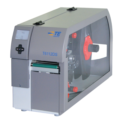
TE Connectivity T6112DS Manual

TE Connectivity
TE Connectivity T2212 User manual

TE Connectivity
TE Connectivity T3212 User manual

TE Connectivity
TE Connectivity T3200 Guide

TE Connectivity
TE Connectivity HTP600 Troubleshooting guide

TE Connectivity
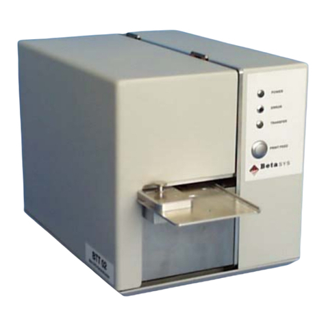
TE Connectivity BTT-02 User manual

TE Connectivity
TE Connectivity T6112DS User manual