TE Connectivity T6112DS Manual

Doc. No: 411-121018
Printhead setup instructions for the
TE3124, TE3112 & T6112DS
Issue: 1
Date: Oct 2012
Author: I Ridgeway
Print date: 24-Oct-12
Issue date: : Oct 2012
Page: 1 of 8
While TE Connectivity has made every reasonable effort to ensure the accuracy of the information in this document, TE does not guarantee that it is
error-free, nor does TE make any other representation, warranty or guarantee that the information is accurate, correct, reliable or current. TE reserves
the right to make any adjustments to the information contained herein at any time without notice. TE expressly disclaims all implied warranties
regarding the information contained herein, including, but not limited to, any implied warranties of merchantability or fitness for a particular purpose.
The dimensions in this document are for reference purposes only and are subject to change without notice. Specifications are subject to change
without notice. Consult TE for the latest dimensions and design specifications.
If this document is printed it becomes uncontrolled
1. Introduction
The aim of this document is to provide instruction for setting up the Printhead of the TE
Connectivity (TE) thermal transfer (TT) printers TE3124 (CC9352-000), TE3112 (CR2120-
000) and T6112DS (CP8122-000) to give an optimum print performance.
The range of products printed on the TE thermal transfer printers TE3124, TE3112 and
T6112DS vary in width and thickness. There is NO universal adjustment to cover every
TE product. It may be necessary to adjust the toggles and printhead for each product
printed.
Note: Thermal transfer Printheads can be damaged by electrostatic discharge or over
current. When ever electrically disconnecting the printhead, the power supply must be
disconnected and allowed to dissipate for at least 1 minute.
The printhead surface can be physically damaged and so must be treated with care. Tools
must not be used on the printhead surface and only the recommended cleaners (TE –
Thermal Transfer [TT] Printer cleaning Kit CP5431-000) are to be used to clean
printheads.
The information contained within this document is the property of TE Connectivity. It is supplied in
confidence and the commercial security of the contents must be maintained. It must not be used for any
purpose other than that for which it is supplied nor may any information contained in it be disclosed to
unauthorised persons. It must not be reproduced in whole or in part without obtaining written permission
from TE Connectivity.

Doc. No: 411-121018
Printhead setup instructions for the
TE3124, TE3112 & T6112DS
Issue: 1
Date: Oct 2012
Author: I Ridgeway
Print date: 24-Oct-12
Issue date: : Oct 2012
Page: 2 of 8
While TE Connectivity has made every reasonable effort to ensure the accuracy of the information in this document, TE does not guarantee that it is
error-free, nor does TE make any other representation, warranty or guarantee that the information is accurate, correct, reliable or current. TE reserves
the right to make any adjustments to the information contained herein at any time without notice. TE expressly disclaims all implied warranties
regarding the information contained herein, including, but not limited to, any implied warranties of merchantability or fitness for a particular purpose.
The dimensions in this document are for reference purposes only and are subject to change without notice. Specifications are subject to change
without notice. Consult TE for the latest dimensions and design specifications.
If this document is printed it becomes uncontrolled
2. Printhead set up
2.1.Toggle Position - place the pressure toggles (Figure 1) on the edges of the
printable area.
Figure 1 - Pressure toggles setup for print area of product to be printed.
Incorrect alignment of pressure toggles can give poor print quality, see Figure 2.
Position of pressure toggles should be optimised for the material printed and is
dependant on width on material printed.
The pressure toggles may be tightly clamped to the printhead locking bar so
movement may be restricted. In this instance loosening the grub screws a quarter
turn (see Figure 3) will aid movement. If grub screws loosened, re-tighten when
pressure toggles positioned in correct location.
Aligned to
print area
Pressure
toggles

Doc. No: 411-121018
Printhead setup instructions for the
TE3124, TE3112 & T6112DS
Issue: 1
Date: Oct 2012
Author: I Ridgeway
Print date: 24-Oct-12
Issue date: : Oct 2012
Page: 3 of 8
While TE Connectivity has made every reasonable effort to ensure the accuracy of the information in this document, TE does not guarantee that it is
error-free, nor does TE make any other representation, warranty or guarantee that the information is accurate, correct, reliable or current. TE reserves
the right to make any adjustments to the information contained herein at any time without notice. TE expressly disclaims all implied warranties
regarding the information contained herein, including, but not limited to, any implied warranties of merchantability or fitness for a particular purpose.
The dimensions in this document are for reference purposes only and are subject to change without notice. Specifications are subject to change
without notice. Consult TE for the latest dimensions and design specifications.
If this document is printed it becomes uncontrolled
Figure 2 - Pressure toggles incorrectly positioned,
showing resultant poor print quality
Figure 3 - Pressure toggle grub screws
Pressure toggles
grub screws

Doc. No: 411-121018
Printhead setup instructions for the
TE3124, TE3112 & T6112DS
Issue: 1
Date: Oct 2012
Author: I Ridgeway
Print date: 24-Oct-12
Issue date: : Oct 2012
Page: 4 of 8
While TE Connectivity has made every reasonable effort to ensure the accuracy of the information in this document, TE does not guarantee that it is
error-free, nor does TE make any other representation, warranty or guarantee that the information is accurate, correct, reliable or current. TE reserves
the right to make any adjustments to the information contained herein at any time without notice. TE expressly disclaims all implied warranties
regarding the information contained herein, including, but not limited to, any implied warranties of merchantability or fitness for a particular purpose.
The dimensions in this document are for reference purposes only and are subject to change without notice. Specifications are subject to change
without notice. Consult TE for the latest dimensions and design specifications.
If this document is printed it becomes uncontrolled
3. Printhead alignment. When the pressure toggles have been correctly positioned,
select and load the recommended thermal transfer ribbon and product combination,
see “Identification printer product ribbon matrix” TE document number 411-121005.
3.1.Close the Printhead and carry out a test print to the printer. Examine the print
quality; if the print quality is not acceptable an adjustment to the printhead position
may be required.
3.2.Figure 4 shows a misalignment of the printhead resulting in poor print quality,
(imbalance –as shown by the alignment witness marks NOT being similarly
located)
Figure 4 - Example of print that requires printer printhead alignment.
Poor print
quality, text
missing
Alignment
witness mark.
Alignment
witness mark.

Doc. No: 411-121018
Printhead setup instructions for the
TE3124, TE3112 & T6112DS
Issue: 1
Date: Oct 2012
Author: I Ridgeway
Print date: 24-Oct-12
Issue date: : Oct 2012
Page: 5 of 8
While TE Connectivity has made every reasonable effort to ensure the accuracy of the information in this document, TE does not guarantee that it is
error-free, nor does TE make any other representation, warranty or guarantee that the information is accurate, correct, reliable or current. TE reserves
the right to make any adjustments to the information contained herein at any time without notice. TE expressly disclaims all implied warranties
regarding the information contained herein, including, but not limited to, any implied warranties of merchantability or fitness for a particular purpose.
The dimensions in this document are for reference purposes only and are subject to change without notice. Specifications are subject to change
without notice. Consult TE for the latest dimensions and design specifications.
If this document is printed it becomes uncontrolled
3.3.When aligning the printhead ensure both sides of the printhead start from the
factory default position with the alignment witness mark in the centre of the
inspection window as shown in Figure 5.
3.4.To align the printhead, remove the ribbon from the printer and loosen the printhead
retaining screw marked “A” shown in Figure 6 with the tool provided with the printer
shown in Figure 6.
Figure 6- Printhead loosening
Screw “A”
Tool provided
with the printer
Alignment witness mark, showing the
factory set alignment of the printhead.
Figure 5 –Factory Default

Doc. No: 411-121018
Printhead setup instructions for the
TE3124, TE3112 & T6112DS
Issue: 1
Date: Oct 2012
Author: I Ridgeway
Print date: 24-Oct-12
Issue date: : Oct 2012
Page: 6 of 8
While TE Connectivity has made every reasonable effort to ensure the accuracy of the information in this document, TE does not guarantee that it is
error-free, nor does TE make any other representation, warranty or guarantee that the information is accurate, correct, reliable or current. TE reserves
the right to make any adjustments to the information contained herein at any time without notice. TE expressly disclaims all implied warranties
regarding the information contained herein, including, but not limited to, any implied warranties of merchantability or fitness for a particular purpose.
The dimensions in this document are for reference purposes only and are subject to change without notice. Specifications are subject to change
without notice. Consult TE for the latest dimensions and design specifications.
If this document is printed it becomes uncontrolled
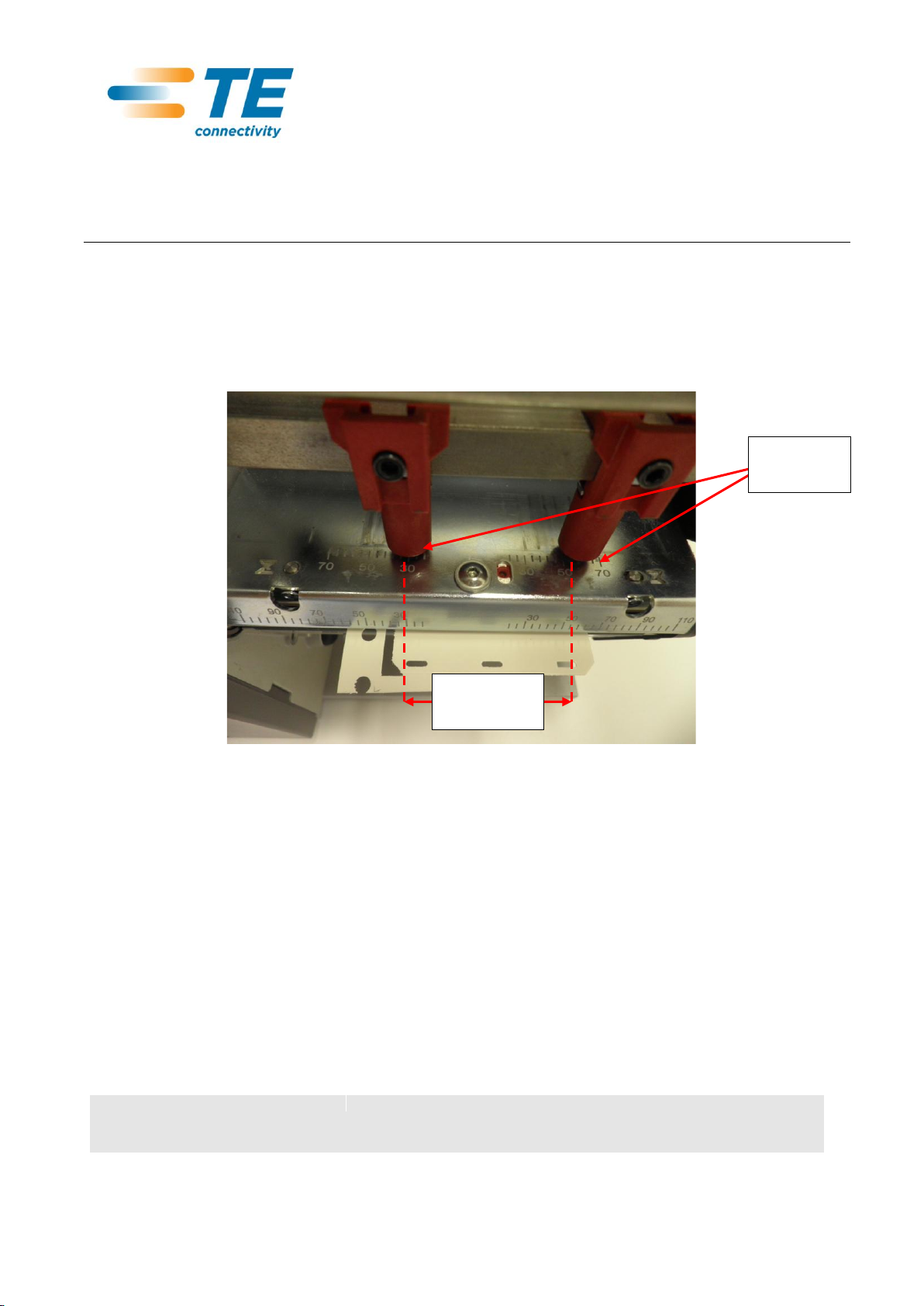
3.5.With screw “A” loose, ensure printhead starting position is with alignment marks in
factory set position. If the print head is not in the factory default position then
adjustment has been previously carried out and this may be the cause of the print
quality issue. In this instance it is advisable to adjust the print alignment screws B
and C (see Figure 7) back to Factory Default, retighten screw A and repeat the
print test (step 3 & 3.1).
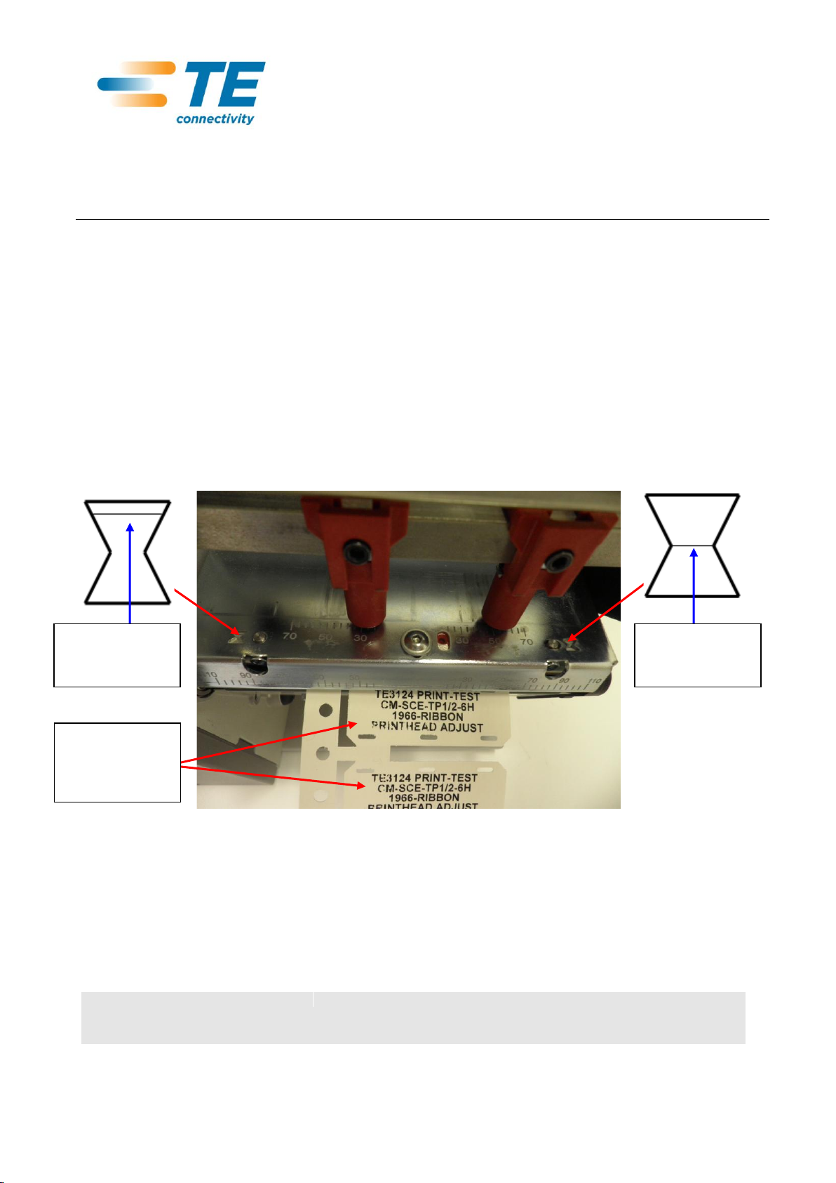
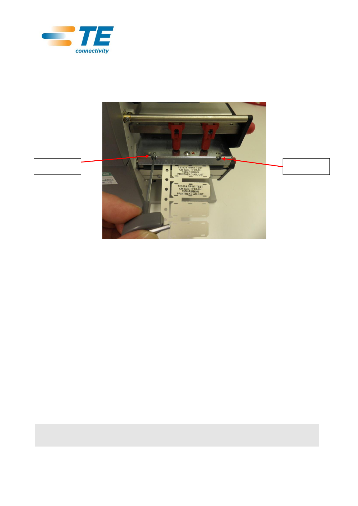
3.6.If the printhead is in the Factory Default then printhead adjustment may be
required. Turn screw B and C one full turn clockwise, see Figure 7) , retighten
screw A and repeat the print test (paragraph 3 –3.1).
3.6.1. If the print test result shows an improvement in print quality loosen screw A
and repeat step 3.5.
3.7.If the print test result shows a deterioration in print quality loosen screw A and Turn
screw B and C two full turns counter-clockwise, see Figure 7) , retighten screw A
and repeat the print test (paragraph 3 –3.1).
3.7.1. If the print test result shows an improvement in print quality loosen screw A
and Turn screw B and C one full turns counter-clockwise, see Figure 7) ,
retighten screw A and repeat the print test (paragraph 3 –3.1).
3.7.2. Optimisation of print quality will occur when print quality starts to fall again, in
which instance loosen screw A and turn one full turn in the opposite direction,
retighten screw A and repeat the print test (paragraph 3 –3.1).
3.8.If print quality does not improve when adjusting the printhead then this may be a
printhead pressure issue, see step 4.

Doc. No: 411-121018
Printhead setup instructions for the
TE3124, TE3112 & T6112DS
Issue: 1
Date: Oct 2012
Author: I Ridgeway
Print date: 24-Oct-12
Issue date: : Oct 2012
Page: 7 of 8
While TE Connectivity has made every reasonable effort to ensure the accuracy of the information in this document, TE does not guarantee that it is
error-free, nor does TE make any other representation, warranty or guarantee that the information is accurate, correct, reliable or current. TE reserves
the right to make any adjustments to the information contained herein at any time without notice. TE expressly disclaims all implied warranties
regarding the information contained herein, including, but not limited to, any implied warranties of merchantability or fitness for a particular purpose.
The dimensions in this document are for reference purposes only and are subject to change without notice. Specifications are subject to change
without notice. Consult TE for the latest dimensions and design specifications.
If this document is printed it becomes uncontrolled
Figure 7 - Printhead alignment screws B and C
4. Printhead Pressure - If changing the location of the pressure toggles, and printhead
alignment does not improve quality then there may be insufficient head pressure.
4.1.To configure the print head pressure, loosen the grub crews holding the pressure
toggles, (see Figure 3) and slide both pressure toggles to their receptive left and
right limits, see figure 8. This will align the printhead pressure adjustment holes
through the printhead locking bar.
Screw “C”
Screw “B”

Doc. No: 411-121018
Printhead setup instructions for the
TE3124, TE3112 & T6112DS
Issue: 1
Date: Oct 2012
Author: I Ridgeway
Print date: 24-Oct-12
Issue date: : Oct 2012
Page: 8 of 8
While TE Connectivity has made every reasonable effort to ensure the accuracy of the information in this document, TE does not guarantee that it is
error-free, nor does TE make any other representation, warranty or guarantee that the information is accurate, correct, reliable or current. TE reserves
the right to make any adjustments to the information contained herein at any time without notice. TE expressly disclaims all implied warranties
regarding the information contained herein, including, but not limited to, any implied warranties of merchantability or fitness for a particular purpose.
The dimensions in this document are for reference purposes only and are subject to change without notice. Specifications are subject to change
without notice. Consult TE for the latest dimensions and design specifications.
If this document is printed it becomes uncontrolled
Figure 8 - Printhead pressure adjust
4.2.Turn the adjustment screws D and E counter-clockwise until turning become
perceptibly easy.
4.3.Turn the adjustment screws D and E clockwise in half turn increments. After each
turn carry out a test print. Note: with pressure toggles positioned at the left and
right extremes the print quality will be less than when placed at their optimum
position.
4.4.Repeat step 4.3 increasing the adjustment on screws D and E in a clockwise
direction until print quality has reached a satisfactory quality.
4.5.When print quality is at an optimum return the pressure toggles to their optimum
position with regards to product and carry out a test print. When adjustment
complete retighten up pressure toggle grub screws (see Figure 3)
4.6.DO NOT adjust screws D and E to the maximum clockwise position as this will
shorten printhead life. If maximum clockwise position is reached then the user
must turn screws D and E one half turn counter-clockwise.
4.7.If print quality does not reach a satisfactory level then contact a TE representative.
Screw “D”
Screw “E”
Other manuals for T6112DS
1
This manual suits for next models
5
Table of contents
Other TE Connectivity Printer manuals

TE Connectivity
TE Connectivity T3212 User manual

TE Connectivity
TE Connectivity T3212 User manual

TE Connectivity
TE Connectivity T3212 User manual

TE Connectivity
TE Connectivity HTP600 Troubleshooting guide

TE Connectivity
TE Connectivity T3200 Guide

TE Connectivity
TE Connectivity T2212 User manual

TE Connectivity
TE Connectivity T2212 User manual

TE Connectivity
TE Connectivity T6112DS User manual

TE Connectivity
TE Connectivity BTT-02 User manual

TE Connectivity
TE Connectivity T2212 User manual