manuals.online logo
Brands
  1. Home
  2. •
  3. Brands
  4. •
  5. Teac
  6. •
  7. Recording Equipment
  8. •
  9. Teac TU-PGRS-G User manual

Teac TU-PGRS-G User manual

D01337601A
Z
Strain gauge load cell Instructions for Use
TU-PGRS-G
Tension/Compression Load Cell
Introduction
Thank you for purchasing the TU-PGRS-G load cell.
Please read this document completely before using this
load cell to achieve its best performance and ensure safe
and proper operation.
Included accessories
If anything is missing or damaged, contact the retailer
where you purchased the product.
Test report
Instructions for Use (this document)
Load button
Company names and product names in this document are the trademarks
or registered trademarks of their respective owners.
IMPORTANT SAFETY INSTRUCTIONS
VWARNING
If something abnormal occurs
In the unlikely event that the product produces smoke, a
strange smell or noise, for example, continuing to use it in
this abnormal state could cause fire or electric shock. After
cutting off the power, confirm that smoke is no longer being
produced. Then, request repair from the retailer where you
purchased the product.
Do not open the cover.
Never remove the cover from this unit. Doing so could
cause electric shock. Request inspection and repair from
the retailer where you purchased the product. Do not
alter this unit. Doing so could cause fire or electric shock.
Do not put foreign objects or water, for example,
into the unit.
Do not place a container that holds water, for example,
on top of this unit. Liquid overflowing or entering the unit
could cause fire or electric shock.
Do not use the unit with any power supply voltage
other than that specified.
Do not use the unit with any power supply voltage other than
that specified. Doing so could cause fire or electric shock.
VCAUTION
Unsuitable installation locations
Do not place the unit in the following types of locations.
Doing so could cause fire or electric shock.
oLocations where it might be exposed to smoke or steam,
such as near a kitchen table or humidifier
oUnstable locations, including unsteady stands and
tilted places
oLocation that are very humid or dusty
oLocations that are exposed to direct sunlight
When not using the unit for a long time
For safety, cut the power supply when not using this
unit for a long time.
Do not operate a damaged unit.
Precautions for use
oThis unit is not built to be water or splash resistant,
and it cannot be used in conditions when the relative
humidity is high. Moreover, use in atmospheres with
corrosive gases should be avoided.
oBe careful to prevent water, oil and other substances
from getting on the unit.
oAvoid use in conditions where condensation could occur.
oConnect cores to the load cell after discharging (elim-
inating) static electricity from your body.
oIf the surrounding temperature changes suddenly,
the values output by this device could become
unstable, making accurate measurement impossible.
(This could occur, for example, in a location blown by
warm or cold air.)
oConduct load calibrations periodically.
Installation procedures
oAttach the load button when using with compression.
Tighten with the torque shown in the table below
to prevent the load button from becoming loose.
When removing an attached load button, be sure not
to apply torque that exceeds the tightening torque
shown in the table.
Rated capacity Tightening
torque
Load button
screw dimension
100N – 1kN 3N·m M8
2kN – 5kN 3N·m M12
10kN – 20kN 3N·m M18
A thread-locking fluid can be used on the screw, but be
aware that this could prevent removal of the load button.
oWhen using with a tensile load, attach a rod end or
tensile load adapter.
oInsert screws (steel hexagon socket head cap screws) into
the screw holes near the edge of the load cell, and fix it to
the flat attachment surface. (Output precision could be
affected if the attachment surface is not flat.) The size of
the screws used and their number depends on the rated
capacity (model name) of the load cell as shown below.
Rated capacity Screw
dimensions Number
Recommended
tightening
torque
100N – 1kN M4 × 35 3 3N·m
2kN – 5kN M6 × 50 6 8N·m
10kN – 20kN M8 × 60 6 30N·m
Use screws with a strength grade of 12.9.
In addition, the contact length for the screw and the
mounting part (internal threads) should be about twice
the nominal diameter of the screw.
Please consult with us if you are uncertain about screw
selection, for example.
oSince tightening screws will cause their heads to contact
the coated surface of the load cell, which could scrape
the coating, use flat washers with the screws so that
the washers contact the load cell instead.
Even using flat washers, the coating could be scraped
if the flat washers are turned.
By using a metal washer like the one shown in the
illustration below, you can avoid scraping the coating
even more.
Screw hole
(Number and diameter
of holes according to
load cell type)
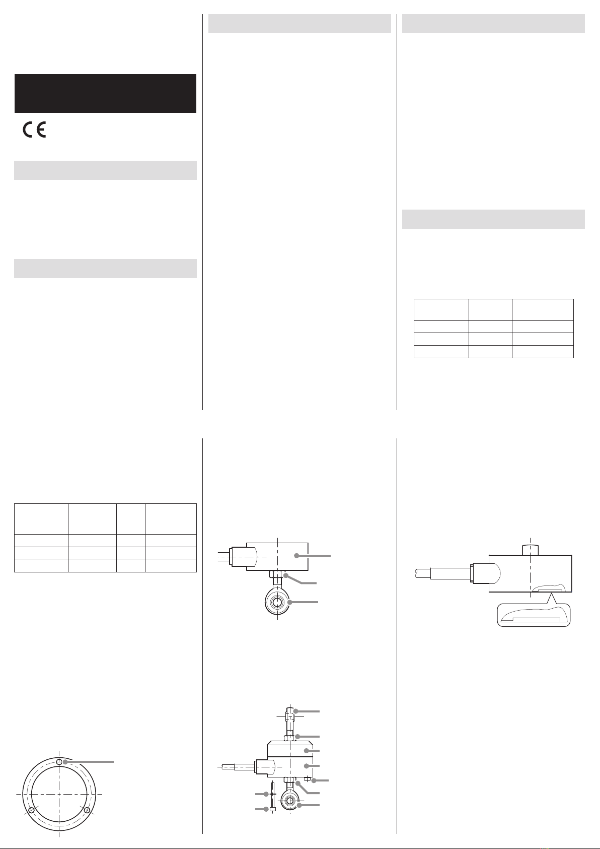
oWhen attaching a rod end to a load cell, use a nut to
prevent loosening. When tightening this nut for the
prevention of loosening, do not allow the counterforce
to be applied to the load cell. (Do not hold the entire
load cell in place while tightening the nut.) If twisting
force is applied between the central screw part and the
surrounding screw holes, that force could be transferred
to the load detection part and damage it. For this reason,
when attaching the nut, hold the rod end side in place.
Do not hold
the load cell
in place.
Nut
Hold the rod end
in place
oIn addition, always use screws that are suitable for the
rated capacity when attaching a base plate or tensile
load adapter, for example, to a load cell. Use flat washers
together with these screws (see the illustration below).
When tightening the rod end nut, do not let the counter-
force be applied to the load cell. (Hold the rod end side.)
Moreover, tighten each of the attachment screws evenly.
Rod end
Nut
Screw and
flat washer
Nut
Rod end
Load cell
Tensile load adapter
Screw
Flat washer
oAs shown in the illustration below, there is a level change
between the outer circumference and the central screw
portion of the load cell attachment surface.
This gap functions as a stopper when the load cell is
overloaded in the compression direction.
For this reason, be aware that if the attachment surface
is uneven, rough, dusty or dirty, for example, the stopper
could function at a load lower than the rated capacity
and produce inaccurate measurement results.
Precautions when placing loads on the
unit
oMake sure the load is perpendicular to the surface to
which this unit is attached.
oApply the load so that it is centered on the center of
the unit. If the load is not centered (eccentric load),
twisting, for example, and measurement errors could
occur. This could even result in damage.
F1 F2F
F is the correct load orientation
F1 is an eccentric inclined load
F2 is an eccentric load
oIf the load receiving area is contacted by something that
is at a different temperature and the load is increased,
the values output by this device could become unstable,
making accurate measurement impossible. In such a
case, wait until the temperature difference ceases to
exist before measuring.
Electrical connection of load cell
oConnect as shown in the illustration below. Incorrect
connections could result in inability to balance and
in errors occurring in the output voltage when loads
are applied.
Using a cable with bare lead wires
Red Input (+)
Black Output (−)
Blue Input (−)
White Output (+)
Yellow Shield
oThe shield is not connected to the main body of this
product. For this reason, if grounding is necessary because
of external noise, for example, arrange to ground the
shield to a part other than the body of this unit.
oSince the cable is directly connected to this unit, use
a specialized cable to increase the length. (Please
consult with us.)
Using a connector (optional)
A Input (+)
B Output (−)
C Input (−)
D Output (+)
E Shield
NDIS-compatible
connector
Handling after use
oWhen moving this unit while it is installed, take protective
measures to prevent it from being shaken or subjected
to excessive external forces.
oWhen storing it, keep it in a dry place where it will not
be exposed to water or oil, for example.
Specifications
TU-PGRS 100N-G to TU-PGRS 20KN-G
Rated capacity: 100N, 200N, 500N, 1kN, 2kN, 3kN, 5kN,
10kN, 20kN
Safe overload rating: 150% R.C.
Rated output: 2mV/V ±0.3%
Linearity: 0.03% R.O.
Hysteresis: 0.03% R.O.
Repeatability: 0.02% R.O.
Zero balance: 3% R.O.
Safe excitation voltage: 15V (100N, 200N)
20V (500N – 20kN)
Input terminal resistance: 1050 ±10
Output terminal resistance: 1050 ±10
Insulation resistance: 1000M or higher (DC50V)
Compensated temperature range: −10 to 60°C
Permissible temperature range: −30 to 80°C
Temperature effect on zero balance: 0.025% R.O./10°C
Temperature effect on output: 0.03% R.C./10°C
Cable: Ø6mm 4-core shielded, 5m direct connection with
bare lead wires (100N  5kN)
Ø8mm 4-core shielded, 5m direct connection with
bare lead wires (10kN, 20kN)
Body material: aluminum (coated surface) (100N–5kN)
Steel (coated surface) (10kN, 20kN)
Environmental compliance: RoHS (10 substances)
TEDS: not supported
Other: load button included
Dimensional drawings (dimensions in millimeters (mm))
A
(Ø14)
Ø58
Ø11
Ø44
Ø11
Ø44
26
B
Rubber sleeve
Cable
M8X1.25
Ø51
3x Ø4.5 through holes
Rated capacity A B
100N 0.15 13
200N 0.15 13
500N 0.09 11.5
1kN 0.09 11.5
TU-PGRS 2K-G to TU-PGRS 5KN-G
(Ø18)
Ø88
Ø62
Ø21
36
18
Rubber sleeve
Cable
M12X1.75
Ø75
6x Ø6.5 through holes
Ø21
Ø62
0.08
TU-PGRS 10K-G to TU-PGRS 20KN-G
Ø118
Ø79
Ø34
40
20
Rubber sleeve
Cable
M18X1.5
Ø98
6x Ø9 through holes
0.08
Ø34
Ø79
R1/2 (PT1/2)
Warranty explanation
oThe warranty period for this device is one year from
the date of purchase.
1) Be aware that repairs will require payment in the
following cases even during the warranty period.
Malfunction or damage due to misuse
2) Malfunction or damage caused by modifications or
repairs conducted by any party other than our com-
pany or a service person designated by our company
3) Malfunction or damage caused by dropping, trans-
portation or similar handling after product delivery
4) Malfunction or damage caused by fire, earthquake,
water, lightning or other natural disaster
5) Malfunction or damage caused by external fac-
tors, including power supplies and equipment
environmental conditions, that deviate from the
operation requirements of this product
6) Malfunction or damage if the product was not pur-
chased from our company or an agent designated
by our company
oWe offer paid service after the conclusion of the warranty
period. For details, please contact the retailer where you
purchased the unit.
oBe aware that our company will bear no responsibility
for any secondary damages resulting from the operation
of this device or related to data.
oInformation is given about products in this manual
only for the purpose of example and does not indicate
any guarantees against infringements of third-party
intellectual property rights and other rights related to
them. TEAC Corporation will bear no responsibility for
infringements on third-party intellectual property rights
or their occurrence because of the use of these products.
Contact information
TEAC CORPORATION (Manufacturer)
1-47 Ochiai, Tama-shi, Tokyo 206-8530 Japan
Phone: +81-042-356-9154
TEAC AMERICA, INC.
10410 Pioneer Blvd. Suite #1, Santa Fe Springs, California90670,
U.S.A.
Phone: +1-323-726-0303
TEAC EUROPE GmbH. (EU Importer)
Bahnstrasse 12, 65205 Wiesbaden-Erbenheim, Germany
Phone: +49-611-7158-349
0720 MA-2733A
TU-PGRS 100N-G to TU-PGRS 1KN-G

Other Teac Recording Equipment manuals

Teac DA-88 User manual

Teac

Teac DA-88 User manual

Teac HD-R1 Instruction Manual

Teac

Teac HD-R1 Instruction Manual

Teac CD-RW890 User manual

Teac

Teac CD-RW890 User manual

Teac HS-2 Manual

Teac

Teac HS-2 Manual

Teac Tascam Porta-02MKII Ministudio User manual

Teac

Teac Tascam Porta-02MKII Ministudio User manual

Teac GX-1 User manual

Teac

Teac GX-1 User manual

Teac LP-R660USB User manual

Teac

Teac LP-R660USB User manual

Teac DS Series User manual

Teac

Teac DS Series User manual

Teac CD-RW890 User manual

Teac

Teac CD-RW890 User manual

Teac CD-RW890MKII User manual

Teac

Teac CD-RW890MKII User manual

Teac Tascam MD-801MKII User manual

Teac

Teac Tascam MD-801MKII User manual

Teac CDR56S-6XX User manual

Teac

Teac CDR56S-6XX User manual

Teac CD-RW2000 Owner's manual

Teac

Teac CD-RW2000 Owner's manual

Teac LP-R550USB User manual

Teac

Teac LP-R550USB User manual

Teac CD-RW901SL User manual

Teac

Teac CD-RW901SL User manual

Teac GF-550 User manual

Teac

Teac GF-550 User manual

Teac GF-350 User manual

Teac

Teac GF-350 User manual

Teac RW-H500 User manual

Teac

Teac RW-H500 User manual

Teac Tascam Series User manual

Teac

Teac Tascam Series User manual

Teac LX Series User manual

Teac

Teac LX Series User manual

Teac TC-FSRSP-G3 User manual

Teac

Teac TC-FSRSP-G3 User manual

Teac GF-350 User manual

Teac

Teac GF-350 User manual

Teac CD-RW890MK2 User manual

Teac

Teac CD-RW890MK2 User manual

Teac RW-D280 User manual

Teac

Teac RW-D280 User manual

Popular Recording Equipment manuals by other brands

DX Engineering DXE-TVSU-1B manual

DX Engineering

DX Engineering DXE-TVSU-1B manual

Sound Devices MixPre-10M quick start

Sound Devices

Sound Devices MixPre-10M quick start

Tronix ROOTS manual

Tronix

Tronix ROOTS manual

Sony STR-DA30ES - Fm Stereo/fm-am Receiver Service manual

Sony

Sony STR-DA30ES - Fm Stereo/fm-am Receiver Service manual

Trane Technologies KIT15864 installation guide

Trane Technologies

Trane Technologies KIT15864 installation guide

Beyerdynamic CA 4588 operating instructions

Beyerdynamic

Beyerdynamic CA 4588 operating instructions

Yamaha CRW4261t-NB user guide

Yamaha

Yamaha CRW4261t-NB user guide

Panasonic WJ-HD716 Specifications

Panasonic

Panasonic WJ-HD716 Specifications

Pioneer PDR-509 Service manual

Pioneer

Pioneer PDR-509 Service manual

Globalstar MRI-1000 installation manual

Globalstar

Globalstar MRI-1000 installation manual

Akai Hexacomp C2M reference guide

Akai

Akai Hexacomp C2M reference guide

Theben 9070771 product manual

Theben

Theben 9070771 product manual

Yamaha CDR-S1000 owner's manual

Yamaha

Yamaha CDR-S1000 owner's manual

Akai DPS24 Service manual

Akai

Akai DPS24 Service manual

Belden Grass Valley NV8900 user guide

Belden

Belden Grass Valley NV8900 user guide

Yamaha RM1x owner's manual

Yamaha

Yamaha RM1x owner's manual

Webasto BlueCool Connect Operating and installation instructions

Webasto

Webasto BlueCool Connect Operating and installation instructions

Atlona AT-GAIN-NET installation guide

Atlona

Atlona AT-GAIN-NET installation guide

manuals.online logo
manuals.online logoBrands
  • About & Mission
  • Contact us
  • Privacy Policy
  • Terms and Conditions

Copyright 2025 Manuals.Online. All Rights Reserved.