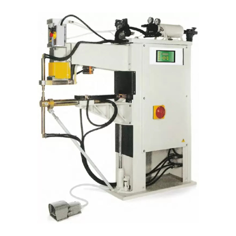
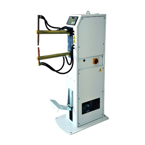
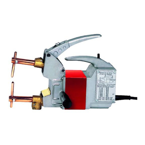
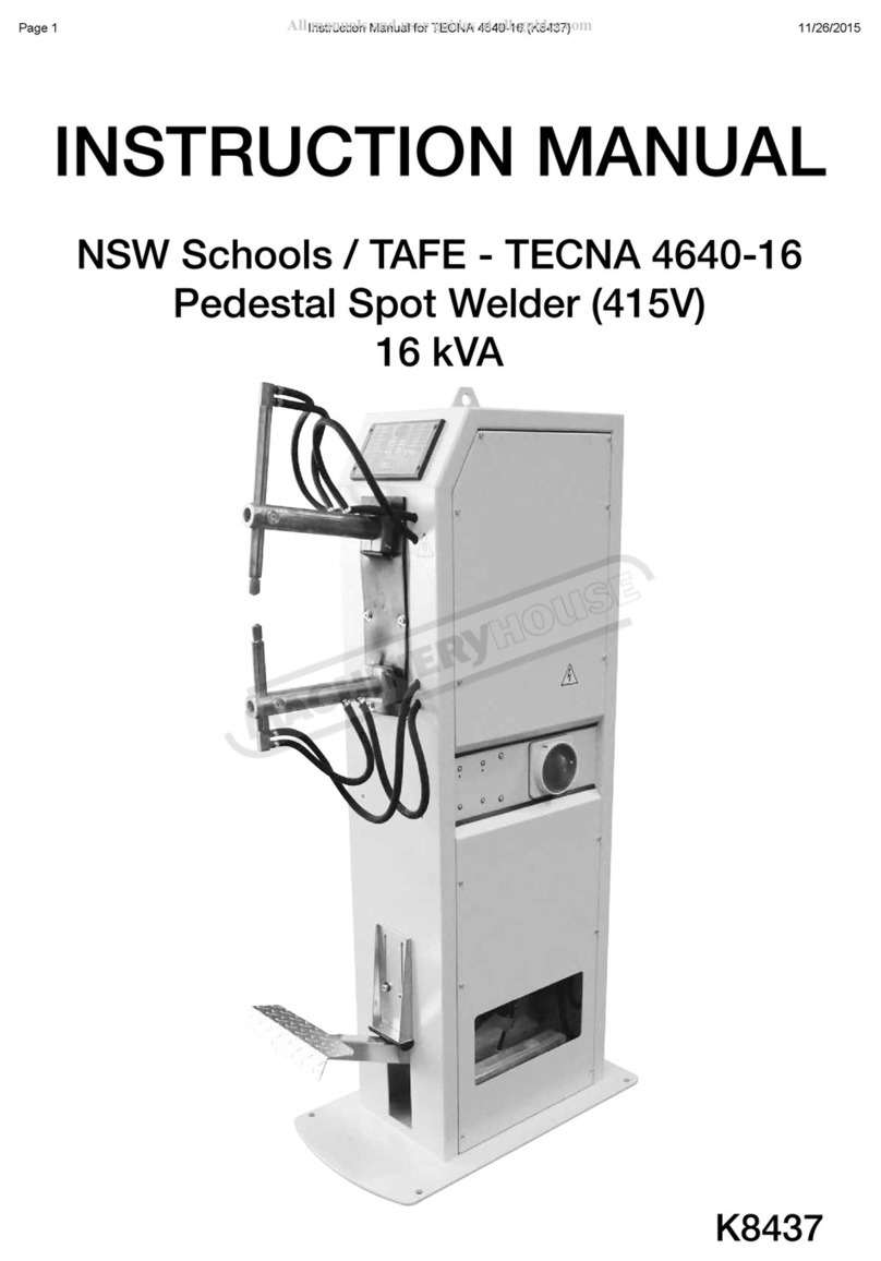
TECNA 3401 Guide

tecn@
SALDATRICI A RESISTENZA
A BRACCIO OSCILLANTE
ROCKER ARM RESISTANCE WELDERS
ART. - ITEM 3401 - 3406 - 3407 - 3408
MANUALE DI INSTALLAZIONE ED USO
INSTALLATION AND USE MANUAL
TECNA S.p.A. Via Grieco 25/27 - 40024 Castel S. Pietro Terme - Bologna ITALY
Tel. (051) 941076 - Tlx 520134 TECNA I - Telefax (051) 941887
DOCUMENTO NUMERO:
DOCUMENT NUMBER:
MAN 1063
DISTRIBUTORE - DISTRIBUTOR:
EDIZIONE:
EDITION:
SETTEMBRE 1997
SEPTEMBER 1997

tecn@ SALDATRICI ART. 3401 - 3406 - 3407 - 3408 WELDERS ITEM 3401 - 3406 - 3407 - 3408
Documento numero / Document number: MAN1063 Edizione / Edition: Settembre / September 1997 PAG. 2 / 32
Questa pagina è stata intenzionalmente lasciata bianca.
This page is left intentionally blank.

tecn@ SALDATRICI ART. 3401 - 3406 - 3407 - 3408 WELDERS ITEM 3401 - 3406 - 3407 - 3408
Documento numero / Document number: MAN1063 Edizione / Edition: Settembre / September 1997 PAG. 3 / 32
INDICE - INDEX
ARGOMENTI - CONTENTS PAGINA - PAGE
1 INTRODUZIONE - INTRODUCTION 5
1.1 PREMESSE - PRELIMINARY REMARKS 5
1.2 SIMBOLOGIA UTILIZZATA SULLA MACCHINA E NEL MANUALE
SYMBOLS ON BOTH WELDER AND MANUAL
5
1.3 DOTAZIONE DI SERIE - STANDARD ACCESSORIES 5
2 CARATTERISTICHE TECNICHE - TECHNICAL FEATURES 6
2.1 DATI DI IDENTIFICAZIONE - IDENTIFICATION DATA 6
2.2 DATI ELETTRICI - ELECTRICAL DATA 6
2.3 DATI MECCANICI - MECHANICAL DATA 7
2.4 DATI DI COLLEGAMENTO CIRCUITO DI RAFFREDDAMENTO
COOLING CIRCUIT CONNECTION DATA
7
2.5 ALTRE CARATTERISTICHE - ADDITIONAL FEATURES 7
2.6 DESCRIZIONE CARATTERISTICHE PRINCIPALI SALDATRICE
WELDER MAIN FEATURES
8
2.7 DESCRIZIONE CONTROLLO DI SALDATURA TE 25
WELDING CONTROL UNIT TE 25 DESCRIPTION
8
3 INSTALLAZIONE - INSTALLATION 9
3.1 LUOGO DI INSTALLAZIONE - PLACE OF INSTALLATION 9
3.2 DISIMBALLAGGIO E TRASPORTO - UNPACKING AND TRANSPORT 9
3.3 INSTALLAZIONE CIRCUITO DI RAFFREDDAMENTO
COOLING WATER INSTALLATION
9
3.4 INSTALLAZIONE ELETTRICA - ELECTRICAL INSTALLATION 10
4 LAVORO - WORKING PROCESS 11
4.1 REGOLAZIONE MECCANICA - MECHANICAL SET UP 12
4.2 REGOLAZIONE FORZA AGLI ELETTRODI - ELECTRODE FORCE ADJUSTMENT 15
4.3 REGOLAZIONE DEL PROGRAMMA DI LAVORO
WORKING PROGRAM ADJUSTMENT
15
4.4 CALCOLO CADENZA MASSIMA DI LAVORO
CALCULATION OF THE MAXIMUM WELDING RATING
16
5 NORME DI SICUREZZA - SAFETY RULES 17
6 RICHIESTA DI ACCESSORI E RICAMBI - ACCESSORIES AND SPARE PARTS REQUEST 18
7 MANUTENZIONE - MAINTENANCE 19
7.1 MANUTENZIONE ORDINARIA - ORDINARY MAINTENANCE 19
7.2 INDICAZIONI PER LE SITUAZIONI DI EMERGENZA
EMERGENCY CONDITION WARNINGS
20
7.3 MANUTENZIONE STRAORDINARIA - EXTRAORDINARY MAINTENANCE 20
7.3.1 DIMINUZIONE DELLE PRESTAZIONI DELLA SALDATRICE
LOWERING OF THE WELDING UNIT PERFORMANCES
20
7.3.2 RICERCA GUASTI - TROUBLESHOOTING 20
7.3.3 SOLUZIONE DEI DIFETTI NELLA SALDATURA
REMEDIES FOR WELDS IMPERFECTIONS
23
8 ALLEGATI - ENCLOSURES 24
8.1 TABELLE DI SALDATURA - WELDING TABLES 24
8.2 ESEMPIO DI SCHEDA DI PRODUZIONE - PRODUCTION FORM FACSIMILE 25
9 DOCUMENTAZIONE TECNICA - TECHNICAL DOCUMENTATION 26
DIMENSIONALE MACCHINA - MACHINE OVERALL DIMENSIONS 26
SCHEMA ELETTRICO - ELECTRICAL DRAWING 27
SCHEMA CIRCUITO DI RAFFREDDAMENTO - COOLING CIRCUIT DRAWING 28
DICHIARAZIONE DEL CONSTRUTTORE - MANUFACTURER DECLARATION 28
ESPLOSI - EXPLODED DRAWINGS 29

tecn@ SALDATRICI ART. 3401 - 3406 - 3407 - 3408 WELDERS ITEM 3401 - 3406 - 3407 - 3408
Documento numero / Document number: MAN1063 Edizione / Edition: Settembre / September 1997 PAG. 4 / 32
Questa pagina è stata intenzionalmente lasciata bianca.
This page is left intentionally blank.

tecn@ SALDATRICI ART. 3401 - 3406 - 3407 - 3408 WELDERS ITEM 3401 - 3406 - 3407 - 3408
Documento numero / Document number: MAN1063 Edizione / Edition: Settembre / September 1997 PAG. 5 / 32
1 INTRODUZIONE
1.1 PREMESSE
LEGGERE ATTENTAMENTE QUESTO MANUALE DI
ISTRUZIONE PRIMA DI INSTALLARE ED UTILIZZARE LA
SALDATRICE.
Il presente manuale è indirizzato al responsabile di
stabilimento che lo deve rendere noto al personale addetto
all’installazione, all’uso e alla manutenzione della saldatrice. Si
deve accertare che le informazioni presentate in questo
documento, e nei documenti allegati, siano state lette e
comprese. Il manuale deve essere conservato in luogo noto e
facilmente accessibile e deve essere consultato ogni qualvolta
sorgano anche piccoli dubbi.
Le saldatrici oggetto di questo manuale sono state progettate per
essere utilizzate solo a scopo professionale in ambiente
industriale. Le saldatrici a resistenza si dividono in due classi:
Classe A: saldatrici destinate ad essere utilizzate in tutti gli
ambienti diversi da quelli domestici e quelli direttamente
connessi a linee di alimentazione pubbliche a bassa tensione
che alimentano edifici utilizzati a scopi domestici.
Classe B: saldatrici destinate ad essere utilizzate in tutti gli
ambienti inclusi quelli domestici e quelli direttamente connessi
a linee di alimentazione pubbliche a bassa tensione che
alimentano edifici utilizzati a scopi domestici.
Ogni saldatrice è disponibile in due versioni diverse
dipendentemente dalle caratteristiche della linea di
alimentazione su cui deve essere utilizzata. Il suffisso B indica
che la saldatrice appartiene alla classe B.
Classe A B
Art. 3401-3406-3407-3408 3401B-3406B-3407B-3408B
ATTENZIONE: le saldatrici di classe A non devono essere
installate su linee pubbliche a bassa tensione che alimentano
edifici domestici. Questo può causare interferenze
elettromagnetiche.
Scopo della macchina è la saldatura a resistenza di materiali
ferrosi. La saldatrice non deve essere utilizzata per altri scopi
come per esempio per riscaldare dei pezzi o effettuare
lavorazioni meccaniche. La macchina è stata progettata per
essere utilizzata da parte di un operatore tramite i dispositivi di
comando previsti. Sono vietati interventi di modifica, anche se
lievi, perchè invalidano la certificazione CE della stessa.
La TECNA S.p.A. si esime da qualsiasi responsabilità per
danni a persone, animali, cose ed alla macchina stessa
causati da un impiego non corretto, dalla mancanza o
superficiale osservanza dei criteri di sicurezza riportati nel
presente manuale, dalle manomissioni anche lievi e
dall’impiego di parti di ricambio non originali o non compatibili.
1.2 SIMBOLOGIA UTILIZZATA SULLA MACCHINA E NEL
MANUALE
ATTENZIONE! Le informazioni contenute in
questo paragrafo sono della massima
importanza.
1.3 DOTAZIONE DI SERIE
La macchina viene consegnata completa delle seguenti parti:
N° 1 Serie chiavi Allen misure 4-5-6-8 mm.
N° 1 Chiave a tubo misura 30-32 mm.
N° 1 Manuale d’uso e manutenzione saldatrice.
Controllare che la macchina sia completa di tutti gli accessori
in dotazione; segnalare tempestivamente al costruttore
eventuali parti mancanti.
1 INTRODUCTION
1.1 PRELIMINARY REMARKS
CAREFULLY READ THIS MANUAL BEFORE INSTALLING
AND OPERATING THE WELDER.
This manual is addressed to the factory responsible in charge
who must release it to the personnel in charge of both welder
installation, use and maintenance. He/she must check that the
information stated on this manual and on the enclosed
documents have been read and understood. The manual must
be stored in a well-known place, easy to reach, and must be
looked up each time even little doubts should arise.
These welders must be installed in industrial environments for
professional use, only. Resistance welding equipment are
classified in Class A and Class B:
Class A resistance welding equipment
Resistance welding equipment suitable for use in all
establishments other than domestic ones and those directly
connected to a low voltage public supply network which supplies
buildings used for domestic purposes.
Class B resistance welding equipment
Resistance welding equipment suitable for use in all
establishments including domestic ones and those
establishments directly connected to a public low voltage
network which supplies buildings used for domestic purposes.
Each welder can be supplied under two different versions
depending on the type of the mains they must be connected to.
The suffix B shows that the welder belongs to the class B.
Class A B
Item 3401-3406-3407-3408 3401B-3406B-3407B-3408B
WARNING: Class A resistance welding equipment are not
intended to be used on a low-voltage public network which
supplies domestic premises. It may cause radio frequency
interference.
This welder has been designed for resistance welding of
ferrous materials. The welder must not be used for other
applications, i.e. pieces heating, mechanical working. The
welder has been designed for being used by an operator by
means of the foreseen control devices. All modifications, even
slight ones, are forbidden because they should invalidate the
welder CE certification.
TECNA S.p.A. is not responsible for any damage to both
people, animals, things and to the welder itself caused by
either a wrong use or the lack or the superficial observance of
the safety warnings stated on this manual, nor it is responsible
for damages coming from even slight tampering or from the
use of not-suitable spare parts, or of spare parts other than the
original ones.
1.2 SYMBOLS ON BOTH WELDER AND MANUAL
WARNING! Important safety information
enclosed in this paragraph.
1.3 STANDARD ACCESSORIES
The welder is supplied equipped with the following
accessories:
N° 1 Allen wrench set 4-5-6-8 mm.
N° 1 Box wrench 30-32 mm.
N° 1 Welder use and maintenance manual.
Check that the welder is equipped with all the standard
accessories; immediately inform the manufacturer in case
some components should lack.

tecn@ SALDATRICI ART. 3401 - 3406 - 3407 - 3408 WELDERS ITEM 3401 - 3406 - 3407 - 3408
Documento numero / Document number: MAN1063 Edizione / Edition: Settembre / September 1997 PAG. 6 / 32
2 CARATTERISTICHE TECNICHE - TECHNICAL FEATURES
2.1 DATI DI IDENTIFICAZIONE - IDENTIFICATION DATA
Articolo Item
Anno di costruzione Year of manufacturing
Numero di serie Serial number
Tensione di rete Mains voltage V
Frequenza di rete Mains frequency Hz
Opzioni
Options
3426
3427
Esecuzione con lunghezza bracci 380÷700 mm anzichè 230÷550 mm. Solo per art. 3407-3408.
Version with adjustable arms length 380÷700 mm instead of 230÷550 mm. For items 3407-3408 only.
Esecuzione con scartamento dei bracci regolabile da 125 a 420 mm. Lunghezza bracci fissa 500 mm.
Solo per art. 3408. - Version with adjustable arms gap from 125 to 420 mm. Fixed arms length 500 mm.
For item 3408 only.
2.2 DATI ELETTRICI - ELECTRICAL DATA
Articolo - Item 3401 3406 3407 3408
Potenza nominale al 50 %
Nominal power at 50 % duty cycle kVA 12 16 20 25
Potenza massima di saldatura
Maximum welding power kVA 28 32 44 62
Tensione alternata secondaria a vuoto
Secondary no load alternate voltage V 3.2 3.4 4 4.6
Corrente termica secondaria al 100 %
Secondary thermal current at 100 % A 2600 3300 3500 3800
Corrente secondaria di corto circuito (L=230 mm)
Short circuit secondary current (L=230 mm) kA 10.5 11.8 14 16.5
Massima corrente di saldatura su alluminio
Maximum welding current on aluminium kA - - - 15.1
Massima corrente di saldatura su acciaio
Maximum welding current on steel kA 8.4 9.4 11.2 13.2
Corrente secondaria di corto circuito con L=550 mm
Short circuit secondary current with L=550 mm kA 7.8 8.3 9.6 11.2
Corrente secondaria di corto circuito con opzione 3426
Short circuit secondary current with option 3426
bracci L=380 mm - arms L=380 mm
bracci L=700 mm - arms L=700 mm
kA
kA
-
-
-
-
11.2
8
13.3
10.1
Corrente secondaria di corto circuito con opzione 3427
Short circuit secondary current with option 3427
scartamento minimo - minimum gap
scartamento massimo - maximum gap
kA
kA
-
-
-
-
-
-
13.8
9.7
Fusibili ritardati - Delayed fuses
220 - 230 - 240 V
380 - 400 - 415 V
A
A
40
25
50
32
63
40
-
50
Sezione cavi di linea per L=10 m *
Mains cables section for L=10 m *
220 - 230 - 240 V
380 - 400 - 415 V
mm2
mm2
10
6
16
6
25
10
-
16
Sezione cavi di linea per L=30 m *
Mains cables section for L=30 m *
220 - 230 - 240 V
380 - 400 - 415 V
mm2
mm2
25
10
25
10
35
10
-
16
Potenza min. del trasformatore di alimentazione **
Supply transformer minimum power **
monofase - single phase
trifase - three phase
kVA
kVA
19
33
22
37
30
51
42
73
* Sezione per ogni cavo, calcolata per cavi unipolari in PVC considerando la saldatrice che assorbe la massima potenza di saldatura con una
caduta di tensione sui cavi del 4%.
** Valore indicativo calcolato per un trasformatore con tensione di corto circuito del 4%, con una caduta di tensione sul trasformatore del 6%, una
caduta sui cavi del 4% e la saldatrice che assorbe la massima potenza di saldatura.
* Section for every cable, calculated for PVC insulated, single conductor cables, considering the welder working at the maximum welding power,
as well as a 4% voltage drop on cables.
** Approximate value, calculated for a transformer with a 4% short circuit voltage, with 6% voltage drop on transformer and a 4% voltage drop on
cables, with the welder adjusted for the maximum welding power.

tecn@ SALDATRICI ART. 3401 - 3406 - 3407 - 3408 WELDERS ITEM 3401 - 3406 - 3407 - 3408
Documento numero / Document number: MAN1063 Edizione / Edition: Settembre / September 1997 PAG. 7 / 32
2.3 DATI MECCANICI - MECHANICAL DATA
Articolo - Item
3401 3406 3407
3407
+
3426
3408
3408
+
3426
3408
+
3427
Profondità min. elettrodi puntatrice
Min. electrodes throat depth L=mm 230 230 230 380 230 380 500
Forza agli elettrodi a 6 bar (600 kPa)
Electrode force at 6 bar (600 kPa) daN 240 240 240 165 240 165 125
Corsa di lavoro
Working stroke mm 8-44 8-44 8-44 10-60 8-44 10-60 10-77
Profondità max. elettrodi puntatrice
Max. electrodes throat depth L=mm 550 550 550 700 550 700 -
Forza agli elettrodi a 6 bar (600 kPa)
Electrode force at 6 bar (600 kPa) daN 115 115 115 90 115 90 -
Corsa di lavoro
Working stroke mm 15-85 15-85 15-85 15-105 15-85 15-105 -
Scartamento bracci
Arms gap
min - mm
max - mm 225 225 225 225 220 220 125
420
Diametro bracci
Arms diameter mm 36 36 36 40
Diametro portaelettrodo
Electrode-holder diameter mm 19 19 19 22
Cono elettrodi Standard ∅(mm) 12.7 12.7 12.7 14.8
Electrodes cone Special ∅(mm)
Peso netto della macchina
Net weight of the machine kg 110 110 115 123
2.4 DATI DI COLLEGAMENTO CIRCUITO DI RAFFREDDAMENTO - COOLING CIRCUIT CONNECTION DATA
Pressione minima dell'acqua bar 2.5
Minimum water pressure kPa 250
Pressione massima dell’acqua bar 4
Maximum water pressure kPa 400
Diametro interno tubi di ingresso/uscita
Hoses inside diameter - input/output mm 10
Consumo minimo per la potenza nominale art./item 3401 3406 3407 3408
Minimum consumption for nominal power l/min 2.5 2.5 3 4
2.5 ALTRE CARATTERISTICHE - ADDITIONAL FEATURES
Articolo - Item 3401 3406 3407 3408
Colore
Machine painting colour
Standard: arancio - orange RAL2004
...........................................................
Rumore aereo prodotto (Livello di pressione acustica
continuo equivalente ponderato A)
Aerial noise produced (Continuous equivalent acoustic
pressure level; A weighed value)
dB (A) < 70 < 70 < 70 < 70
Posizione di misura - Measurement position h=1,60 m L=0,5 m
Condizione di misura - Measurement conditions
corsa - working stroke
tempo di saldatura - welding time
corrente di saldatura - welding current
duty cycle di lavoro - working rating
mm
cicli - cycles
kA
sald./min
welds/min
20
19
7.8
10
20
24
8.8
10
20
17
11.2
10
20
14
13.2
10

tecn@ SALDATRICI ART. 3401 - 3406 - 3407 - 3408 WELDERS ITEM 3401 - 3406 - 3407 - 3408
Documento numero / Document number: MAN1063 Edizione / Edition: Settembre / September 1997 PAG. 8 / 32
2.6 DESCRIZIONE CARATTERISTICHE PRINCIPALI DELLA
SALDATRICE
• Puntatrice a colonna con azionamento a pedale a braccio
oscillante, completa di controllo di saldatura elettronico
TE25.
• Bracci regolabili in lunghezza che consentono di adattarla al
lavoro da svolgere.
• Portaelettrodi in rame-cromo, consentono servizio pesante e
lunga durata con un minimo ingombro e sono previsti per un
montaggio dritto e inclinato.
• Corsa degli elettrodi regolabile.
• Trasformatore raffreddato integralmente ad acqua,
incapsulato in resina epossidica
• Termostato di protezione.
• Bracci, portaelettrodi ed elettrodi raffreddati ad acqua.
• Comando sincrono con SCR isolati dall'acqua di
raffreddamento.
• Forza agli elettrodi regolabile, un microinterruttore comanda
il ciclo di saldatura quando con il pedale si raggiunge il
valore di forza regolato.
• Pedale regolabile in lunghezza.
2.7 DESCRIZIONE CONTROLLO DI SALDATURA TE 25
Il TE 25 è un controllo di saldatura a microprocessore per
saldatrici monofasi a resistenza. La funzione del controllo di
saldatura è quello di gestire l’erogazione della corrente di
saldatura. La durata dell’erogazione di corrente (TEMPO) e la
sua intensità (CORRENTE) vengono regolate con due
manopole.
CARATTERISTICHE PRINCIPALI
• Comando sincrono a diodi controllati con regolazione della
corrente di saldatura a controllo di fase.
• Modalità di funzionamento a pulsazioni.
• Funzione di compensazione della corrente secondaria per la
saldatura di lamiere e tondini con tracce di ruggine.
• Ingresso per termostato di protezione.
• Regolazione del ritardo di prima inserzione, ottimizza il
bilanciamento dell'assorbimento di linea della macchina.
SPIE SUL CONTROLLO
ACCESO - Indica che la saldatrice è accesa.
INIZIO CICLO - Indica che il comando di inizio ciclo è azionato.
CORRENTE - Indica che il controllo sta generando gli impulsi
di comando per gli SCR.
TERMOSTATO - Indica che è intervenuto il termostato di
protezione. Il funzionamento della saldatrice è
temporaneamente bloccato.
2.6 WELDER MAIN FEATURES
• Rocker arm, foot operated, spot welder, with electronic
welding control unit TE25.
• Arms adjustable in length according to the job to be carried
out.
• Chrome-copper electrode holders for long life and heavy
duty service, designed for straight and angled fitting.
• Adjustable electrodes stroke.
• Epoxy coated, water-cooled transformer.
• Protection thermostat.
• Water cooled arms, electrode-holders and electrodes.
• Synchronous SCR contactor insulated from cooling water
circuit.
• Adjustable electrode force; a microswitch starts the welding
cycle when the desired pre-set value is reached.
• Foot control adjustable in length.
2.7 WELDING CONTROL UNIT TE 25 DESCRIPTION
TE 25 is a microprocessor welding control unit for single-phase
resistance welders. The welding control unit is used to control
the thyristor adjusting the welding current. The length of
current circulation (TIME) and its intensity (CURRENT) are
adjusted by means of two knobs.
MAIN FEATURES
• Synchronous thyristor drive, phase shift control for welding
current adjustment.
• Pulse function.
• Secondary current compensation function for the welding of
oxidised sheets and rods.
• Input for protection thermostat.
• First phase shift delay adjustment. It enables the machine
line current best balance.
CONTROL PANEL PILOT LIGHTS
ON - It signals that the welder is on.
START - It signals that the start of cycle device is activated.
CURRENT - It signals that the control unit is generating the
control impulses for SCR.
THERMOSTAT - It signals that the protection thermostat is
activated. The welder working is temporaly stopped.

tecn@ SALDATRICI ART. 3401 - 3406 - 3407 - 3408 WELDERS ITEM 3401 - 3406 - 3407 - 3408
Documento numero / Document number: MAN1063 Edizione / Edition: Settembre / September 1997 PAG. 9 / 32
3 INSTALLAZIONE
I presenti paragrafi sono destinati al personale specializzato
addetto al trasporto ed all’installazione della macchina. Nelle
ultime pagine di questo manuale è presente il disegno
d’ingombro della macchina che riporta indicazioni necessarie a
svolgere queste operazioni.
3.1 LUOGO DI INSTALLAZIONE
La macchina va installata in una posizione che soddisfi le
seguenti caratteristiche:
• In ambiente chiuso, non è previsto l’uso della saldatrice in
luogo aperto.
• Con temperatura ambientale compresa tra 0 e 40 °C (per il
solo magazzinaggio, qualora venga tolta l'acqua dal circuito
di raffreddamento, la macchina può essere tenuta fino a -20
°C) ed altitudine non superiore ai 1000 m.
• In una zona ben aerata, libera da polvere, vapori, esalazioni
acide.
• Il luogo di lavoro deve essere privo di materiali infiammabili
in quanto la lavorazione può comportare proiezioni di
particelle di metallo fuso.
• Intorno alla saldatrice deve rimanere lo spazio necessario ad
eseguire agevolmente e senza rischi la lavorazione e la
manutenzione.
• In luogo adeguatamente illuminato in relazione al lavoro da
compiere.
• La posizione di installazione deve necessariamente essere
piana ed il pavimento privo di asperità che possano creare
rischi durante la lavorazione.
Se si prevede di utilizzare la macchina per saldature che
possano generare fumi si deve installare un adeguato impianto
di aspirazione. La saldatrice deve essere fissata al pavimento
tramite adeguati tasselli, utilizzando gli appositi fori previsti
sulla base della macchina. Non installare in prossimità della
macchina tavole di supporto o attrezzature che riducano
l’accesso ai dispositivi di comando e/o rendano irraggiungibili o
inefficaci i dispositivi di protezione.
3.2 DISIMBALLAGGIO E TRASPORTO
Al ricevimento della macchina verificare la perfetta integrità
esterna dell’imballo e denunciare ad un responsabile eventuali
anomalie riscontrate. Eventuali danneggiamenti dell’imballo
dovrebbero far sorgere dubbi sull’integrità del suo contenuto.
Rimuovere l’imballo e verificare visivamente l’integrità della
macchina. Controllare che la macchina sia completa di tutti gli
accessori in dotazione; segnalare tempestivamente al
costruttore eventuali parti mancanti. Tutto il materiale che
compone l’imballo deve essere smaltito nel pieno rispetto delle
vigenti normative sulla protezione ambientale.
Il baricentro della macchina è alto da terra. Questo comporta
che la saldatrice deve essere movimentata unicamente
utilizzando l’apposito aggancio posto nella parte superiore.
Tenere conto del peso della macchina indicato nel paragrafo
“CARATTERISTICHE TECNICHE”.
3.3 INSTALLAZIONE CIRCUITO DI RAFFREDDAMENTO
Per un corretto raffreddamento della puntatrice è necessaria
acqua pulita con temperatura massima di 30 °C nella quantità
indicata nel paragrafo “Caratteristiche tecniche”. Al momento
del collegamento fare attenzione che non vi sia sporco o
frammenti di imballi nei tubi e collegare l'alimentazione
all'ingresso e lo scarico all'uscita, ciò per permettere all'acqua
ancora fredda di raggiungere prima i punti della macchina più
soggetti a riscaldarsi.
E' possibile eseguire il circuito di raffreddamento in modi
diversi: con acqua a perdere, a circuito chiuso, con
scambiatore di calore acqua-aria e con refrigeratore. Se il
circuito è a perdere o con refrigeratore e si lavora con una
elevata umidità si consiglia di evitare l'uso di acqua a bassa
temperatura perché porterebbe alla formazione di condensa
all'interno della macchina.
3 INSTALLATION
These paragraphs are addressed to the specialised personnel
in charge of both welder handling and installation. The welder
dimensions drawing, placed in last pages of this manual,
provides useful information for carrying out these operations.
3.1 PLACE OF INSTALLATION
The welder must be installed in a position fulfilling the following
features:
• In an inner place. The welder has not been designed for
being used in an open place.
• Room temperature included between 0 and 40 °C (If water is
removed, storage is allowed down to 20°C below 0); 1000 m.
maximum altitudes.
• In a well ventilated area, free from dust, steam, and acid
exhalations.
• The working place must be free from inflammable materials
because the working process can produce spatters of melted
metal.
• Around the welder there must be enough room to carry out
both working and maintenance in a comfortable manner and
without any risk.
• In a place with a suitable lighting system in comparison with
the work to be carried out.
• The place of installation must necessarily be flat and the
ground must be without unevenness which can be
dangerous during the working.
If the welder is used to carry out welding processes which can
cause smoke exhalations, there must be installed a proper
aspirator. The welder must be carefully fixed to the floor
through the proper holes placed on the welder basement. Do
not install nearby the welder neither supporting tables, nor
equipment limiting the approaching to the devices and/or
making inaccessible or ineffectual the safety devices.
3.2 UNPACKING AND TRANSPORT
On receipt of the welder, verify the perfect integrity of the outer
package; communicate to a responsible in charge possible
anomalies which should be noticed. Possible damages on the
outer package should arise some doubts on the integrity of its
content. Remove the package and visually verify the welder
integrity. Check that the welder is equipped with all the
standard components; immediately inform the manufacturer in
case some components should lack. All the material forming
the package must be removed according to the present
environmental protection regulations.
The welder barycentre is high from ground. For this reason,
the welder must be moved only by means of the proper
attachment placed on the unit upper side. Consider the welder
weight stated on the “TECHNICAL FEATURE” paragraph.
3.3 COOLING WATER CONNECTION
For a correct cooling of the welder it is necessary clean water
at a maximum temperature of 30°C at the quantity stated on
the paragraph “Technical features”. When connecting the unit
to the water line check for dirt or packing scraps in the hoses
and connect the supply to the inlet, and the drain to the outlet,
this to allow that the still cool water immediately reaches the
parts of the welder most subject to heating.
Different cooling circuit systems are available: with city supply
water, with re-circulating water, with heat exchanger (air-water)
and with refrigerator. If the circuit is with city supply or
refrigerator and you are working in presence of high humidity,
we suggest to avoid the use of low temperature water, as this
could produce moisture inside the machine.

tecn@ SALDATRICI ART. 3401 - 3406 - 3407 - 3408 WELDERS ITEM 3401 - 3406 - 3407 - 3408
Documento numero / Document number: MAN1063 Edizione / Edition: Settembre / September 1997 PAG. 10 / 32
In presenza di acque dure o calcaree è necessario installare
un addolcitore all'ingresso del circuito di raffreddamento della
puntatrice; ciò per evitare che a lungo andare depositi calcarei
ostruiscano o riducano i canali di raffreddamento causando
danni alla macchina. Nel caso di raffreddamento a circuito
chiuso, questo addolcitore va posizionato sull’alimentazione
della vasca che contiene l'acqua di raffreddamento.
3.4 INSTALLAZIONE ELETTRICA
Verificare innanzitutto che la classe della macchina sia adeguata
all’ambiente in cui deve essere installata.
ATTENZIONE: le saldatrici di classe A non devono essere
installate su linee pubbliche a bassa tensione che alimentano
edifici domestici. Questo può causare interferenze
elettromagnetiche.
L'installazione deve essere eseguita unicamente da personale
specializzato a conoscenza delle norme di sicurezza. Siccome
la puntatrice può essere fornita a diverse tensioni di
alimentazione, prima di collegare la macchina alla linea
controllare che la tensione di rete coincida con quella indicata
sulla targa della puntatrice.
Consultare la tabella dei dati caratteristici per determinare la
sezione dei cavi da utilizzare in relazione alla lunghezza degli
stessi. In questa tabella è riportato anche il valore dei fusibili
che devono essere posti sull'alimentazione della saldatrice,
questi devono assolutamente essere di tipo ritardato.
Collegare la saldatrice a terra con un cavo di sezione uguale a
quello utilizzato per l'alimentazione. Si consiglia di alimentare
la saldatrice attraverso un sezionatore di linea per agevolare le
operazioni di manutenzione.
La saldatrice è costruita per essere utilizzata unicamente alla
tensione di alimentazione indicata sulla targa, non è
predisposta per poter essere regolata per altre tensioni di
alimentazione.
In presence of hard water it is necessary to install a water
softener at the cooling circuit inlet hose, this to avoid that
deposits obstruct or reduce the water channels in the welder,
thus causing damages. If the machine is operated in a re-
circulating water supply, the water softener must be placed on
the supply of the cooling water tank.
3.4 ELECTRICAL INSTALLATION
First check that the machine is of the right class in comparison
with the working environment.
WARNING: Class A resistance welding equipment are not
intended to be used on a low-voltage public network which
supplies domestic premises. It may cause radio frequency
interference.
Installation must be carried out by specialised personnel only,
aware of all safety rules. As this unit can be supplied for
different power supply versions, before connecting the unit to
the power line, check if the voltage shown on the features plate
corresponds to the one of your power supply.
Consult the “technical features” paragraph to determine the
cables section to be used, according to their length. On this
paragraph you find also the values of the fuses which must be
placed on the welder supply input. Fuses must be delayed type
only. Connect the machine to earth by using a cable having the
same section of the mains cable. In order to facilitate the
maintenance operation, we recommend you to supply the
welder machine by means of a mains disconnecting switch.
The welder has been designed to work only at the mains
voltage shown on the plate. It cannot be adjusted to work at
different mains voltages.

tecn@ SALDATRICI ART. 3401 - 3406 - 3407 - 3408 WELDERS ITEM 3401 - 3406 - 3407 - 3408
Documento numero / Document number: MAN1063 Edizione / Edition: Settembre / September 1997 PAG. 11 / 32
4 LAVORO
La saldatrice è stata progettata per essere utilizzata da un
operatore posto di fronte alla saldatrice ed operante sullo
stesso piano di lavoro sul quale è posta la macchina.
Nella preparazione del posto di lavoro tenere sempre presente
le seguenti indicazioni:
• Utilizzare una zona ben aerata, libera da polvere, vapori,
esalazioni acide.
• Il luogo di lavoro deve essere privo di materiali infiammabili
in quanto la lavorazione può comportare proiezioni di
particelle di metallo fuso.
• Intorno alla saldatrice deve rimanere lo spazio necessario ad
eseguire agevolmente e senza rischi la lavorazione e la
manutenzione.
• Se si prevede di utilizzare la macchina per saldature che
possano generare fumi si deve installare un adeguato
impianto di aspirazione.
• Non installare sulla macchina tavole di supporto o
attrezzature che rendano irraggiungibili o riducano l’efficacia
dei dispositivi di protezione.
Le regolazioni da effettuare prima di iniziare il lavoro sono le
seguenti:
1 - Regolazione meccanica
2 - Regolazione forza agli elettrodi
3 - Regolazione dei parametri di saldatura
4 - Calcolo cadenza massima di lavoro
I paragrafi seguenti descrivono in maniera approfondita queste
diverse fasi.
Prima di iniziare il lavoro verificare che siano state messe in
opera tutte le prescrizioni di sicurezza. Verificare che lo scatto
del microinterruttore avvenga qualche centimetro prima che il
pedale tocchi terra.
Azionando il pedale si chiudono gli elettrodi, quando con il
pedale si raggiunge il valore di forza regolato un
microinterruttore aziona il timer che inserisce la corrente di
saldatura per il tempo regolato.
Una volta terminato il passaggio di corrente è necessario
mantenere gli elettrodi chiusi ancora per qualche istante, per
evitare di sollecitare il punto di saldatura prima di un adeguato
raffreddamento. Questo accorgimento permette di migliorare la
tenuta del punto.
E' inoltre opportuno, prima di iniziare il lavoro, verificare le
condizioni di saldatura (tempo, forza, elettrodi, ecc.). Utilizzare
due ritagli della lamiera che si dovrà saldare, si eseguano due
punti alla distanza che avranno nella produzione, si elimini il
primo e si esamini il secondo: il punto è corretto quando la
prova di rottura a trazione provoca l'estrazione del nocciolo di
saldatura col foro di una lamiera, la rottura per torsione mostra
un'area sana senza porosità o provoca l'estrazione del
nocciolo.
4 WORKING PROCESS
The welder has been designed for being used by an operator
placed in front of the unit and operating on the welder same
working plane. When arranging the working place, always
follow the herewith stated instructions:
• Use a well ventilated area, free from dust, steam, and acid
exhalations.
• The working place must be free from inflammable materials
because the working can produce spatters of melted metal.
• Around the welder there must be enough room to carry out
both working and maintenance in a comfortable manner and
without any risk.
• If the welder is used to carry out welding processes which
can cause smoke exhalations, there must be installed a
proper aspirator.
• Do not install on the welder neither supporting tables nor
equipment which either limit the approaching to the devices
or make inaccessible or ineffectual the safety devices.
Before starting the working process, carry out the following
adjustments:
1 - Mechanical set up
2 - Electrode force adjustment
3 - Welding parameters adjustment
4 - Calculation of the maximum welding rating
The following paragraphs carefully explain these different
phases.
Before starting the working process check that all the safety
instructions have been operated. Make sure that the micro-
switch is triggered a few centimetres before the pedal touches
the ground.
By activating the foot-control, the electrodes close; when the
pre-set force value is reached, a microswitch activates the
timer which switches on the welding current for the selected
time.
When the current has stopped, the electrodes must be kept
closed for a few moments, this to avoid the spot being stressed
before sufficiently cooled. This precaution enables to improve
the weld quality.
Before starting the welding process, check the welding
conditions (time, force, electrodes, etc.). Use two off-cuts of
the sheet to be welded, carry out two spots at the same
distance used during the production, then remove the first and
check the second: the spot is correct when the pulling test
causes the coming out of the weld nugget with the hole of a
sheet, and the twist test shows a pure area without porosity or
causes the coming out of the nugget.

tecn@ SALDATRICI ART. 3401 - 3406 - 3407 - 3408 WELDERS ITEM 3401 - 3406 - 3407 - 3408
Documento numero / Document number: MAN1063 Edizione / Edition: Settembre / September 1997 PAG. 12 / 32
Durante la produzione è consigliabile tenere sotto controllo
quei parametri che possono variare le condizioni di lavoro e di
conseguenza la qualità della saldatura ottenuta.
Tenere sempre controllati gli elettrodi che devono essere
sempre puliti, privi di deformazioni e mantenuti del diametro
necessario al lavoro da eseguire.
Non utilizzare prodotti sigillanti per eliminare perdite
sull'attacco conico degli elettrodi. Per facilitare l'estrazione
dell'elettrodo ed evitare il grippaggio del cono e le perdite può
essere utilizzato grasso ad elevata conducibilità.
L'acqua di raffreddamento deve circolare nella saldatrice per
alcuni minuti dopo che si è terminata la produzione per
permettere il raffreddamento della macchina. Non lasciare
comunque inutilmente il circuito di raffreddamento aperto a
macchina inutilizzata per evitare perdite e la formazione di
condensa.
Gli elettrodi non devono essere utilizzati per avvicinare
forzatamente i pezzi da saldare.
Si consiglia di annotare per ogni tipo di pezzo le regolazioni
effettuate. Nelle ultime pagine di questo manuale abbiamo
inserito un modulo per facilitare questo compito.
4.1 REGOLAZIONE MECCANICA
Regolazione dei bracci e degli elettrodi
I bracci sono regolabili in lunghezza per adattare la macchina
alle diverse esigenze di lavoro. L’aumento della lunghezza dei
bracci provoca una riduzione delle prestazioni per cui è
sempre consigliabile lavorare con la regolazione minore
possibile. Regolare la lunghezza del pedale per per adattarlo
alla regolazione dei bracci. I bracci ed i portaelettrodi devono
essere regolati in modo che le punte degli elettrodi, nella
condizione di lavoro, coincidano perfettamente. I bracci,
quando stringono i pezzi da saldare, devono risultare paralleli.
Eseguire delle prove con il controllo regolato in modalità NON
SALDA, alla forza agli elettrodi necessaria per eseguire il
lavoro, interponendo fra gli elettrodi uno spessore pari a quello
che si deve saldare. Se necessario sfilare il bracci e i
portaelettrodi ed effettuare la regolazione.
E' sempre opportuno sistemare gli elettrodi con una lima fine o
con tela abrasiva. I migliori risultati si ottengono utilizzanto
della tela abrasiva avvolta su un sostegno dello stesso
spessore delle lamiere da saldare.
Il diametro degli elettrodi deve essere portato ad un valore
adatto alla saldatura che si deve eseguire, tenendo conto dello
spessore delle lamiere, del tipo di materiale e della classe di
saldatura prescelta. Per la saldatura di acciaio si consigliano i
seguenti valori:
During the production it is advisable to monitor those
parameters which can alter the working conditions, and thus
the welds quality.
Always monitor the electrodes which must always be clean,
without any deformation and must have the proper diameter
according to the work to be carried out.
Do not use sealing products to remove water losses on the
electrodes conic connection. To facilitate the electrode removal
and to prevent from both cone seizure and water losses, use
high conductivity grease.
The cooling water must circulate inside the welder for a few
minutes after having completed the production in order to allow
the welder cooling. To prevent from both losses and moisture
deposits, do not leave the cooling circuit open when the unit is
not used.
Electrodes must not be used to force the clamping of the
pieces to be welded.
We recommend you to notice the adjustments carried out for
each type of piece. In order to make it easier, a specific table
has been added at the end of this manual.
4.1 MECHANICAL SET UP
Arms and electrodes adjustment.
The arms length can be adjusted in comparison with the
different working exigencies. The lengthening of the arms
causes a decreasing of the performances, so that it is
advisable always to work with the shortest available length.
Adjust the foot-control length according to the arms set-up.
Under working conditions, both arms and electrodes holder
must be adjusted in order to have the electrodes tip coincide.
When clamping the pieces to be welded, the arms must be in
a parallel position.
Carry out some tests with the control unit on NO WELD mode,
using the same electrodes force employed to carry out the
work; place between the electrodes a thickness equal to that
which must be welded. If it is necessary, pull out both arms
and electrodes holder and carry out the adjustment operations.
It is advisable to adjust electrodes with a fine file or with
sandpaper. The best performances can be reached by using
sand paper folded upon a support having the same thickness
of the sheets to be welded.
The diameter of the electrodes must be adjusted to a value
suitable for the welding to be carried out. The sheets
thickness, the kind of material and the chosen welding class
must be taken into account. The following values are
suggested when welding steel:
Spessore lamiere - Sheet thickness mm 0,5 0,8 1 1,5 2 2,5 3 3,5 4
Diametro elettrodi - Electrodes diameter mm 4 4,5 5 6 7 7,5 8,5 9,5 11

tecn@ SALDATRICI ART. 3401 - 3406 - 3407 - 3408 WELDERS ITEM 3401 - 3406 - 3407 - 3408
Documento numero / Document number: MAN1063 Edizione / Edition: Settembre / September 1997 PAG. 13 / 32
L'angolo della punta dell'elettrodo suggerito è 120 gradi. Se lo
spessore delle lamiere è diverso la punta dell'elettrodo deve
avere il diametro corrispondente alla lamiera con cui viene a
contatto. Un diametro degli elettrodi troppo piccolo in relazione
allo spessore da saldare porta a spruzzi di materiale fuso,
eccessiva impronta sulla lamiera, scarsa tenuta del punto.
Elettrodi di diametro troppo elevato portano a dover utilizzare
tempi di saldatura maggiori che portano ad un maggiore
riscaldamento della saldatrice e ad una minor vita degli
elettrodi. Nel caso di saldatura a punti di alluminio si consiglia
di usare elettrodi sferici, il valore del raggio varia in relazione
allo spessore da saldare e alla qualità che si vuole ottenere.
Regolazione scartamento nelle macchine dotate
dell’opzione 3427 o del kit 3437.
In queste puntatrici si è scelta la profondità degli elettrodi fissa
a 500mm e lo scartamento regolabile fino ad un massimo di
500mm. Lo scartamento è regolabile per adattare la saldatrice
alle diverse esigenze di lavoro, lo scartamento elevato riduce
le prestazioni; di ciò è opportuno tener conto nella regolazione
dei parametri di saldatura. E’ possibile il montaggio in diverse
posizioni:
A - Lo scartamento può raggiungere il massimo.
B - Capovolgendo il supporto 3 e spostando il portabraccio 4 in
alto si ottiene lo scartamento minimo.
C - Per saldature su bordi difficili da raggiungere è possibile
disallineare gli elettrodi. L’inclinazione va mantenuta entro un
max di 20° per evitare spostamenti sotto sforzo.
Suggested electrode tip angle is 120 degrees. If the thickness
of the two plates is different, the electrode must have the
diameter corresponding to the one required by the plate to
which it gets in touch with.
A too small diameter in comparison with the thickness to be
welded produces spatters of melted material, sheets over
mark, low spot quality. If the electrode diameter is too large,
longer welding times are necessary, causing a higher heating
of the welder and a shorter life of the electrodes. For
aluminium spot welding we suggest to use spherical
electrodes, radius value varies according to the thickness to be
welded and to the kind of quality required.
Arms gap adjustment on welders with option 3427 or kit
3437.
In these spot welders it has been chosen an electrodes depth
fixed at 500mm and an arms gap adjustable up to a maximum
of 500mm. The arms gap can be adjusted in order to meet
different working exigencies; a large arms gap causes a
decreasing of the performances so that it is necessary to take
this into account when adjusting the welding parameters. It is
possible to assemble the arms in different positions:
A - The arms gap can reach the maximum.
B - The minimum gap is obtained by turning upside down the
support 3 and by pushing upwards the armholder 4.
C - When welding difficult-to-reach edges it is possible to put
the electrodes out of alignment. The inclination should be kept
within 20° max. so to avoid displacement under effort.

tecn@ SALDATRICI ART. 3401 - 3406 - 3407 - 3408 WELDERS ITEM 3401 - 3406 - 3407 - 3408
Documento numero / Document number: MAN1063 Edizione / Edition: Settembre / September 1997 PAG. 14 / 32
Regolazione della corsa di lavoro
Regolare la corsa di lavoro al valore minore possibile per
ottenere:
• Maggiore produttività.
• Maggiore precisione di lavoro.
• Ridotte possibilità di infortunio.
La regolazione della corsa di lavoro si effettua eseguendo le
seguenti operazioni:
1) Spegnere la saldatrice.
2) Rimuovere la protezione di sicurezza 39360.
3) Allentare il dado 10262 con la chiave a tubo fornita in
dotazione.
4) Regolare la corsa di lavoro ruotando la vite in testa all’asta
con una chiave allen di 8 mm. La regolazione si effettua
tenendo conto che i bracci, quando stringono i pezzi da
saldare, devono risultare paralleli.
5) Serrare bene il dado 10262.
6) Rimontare la protezione di sicurezza 39360.
7) Accendere la saldatrice.
Sulla parte frontale della macchina il limitatore di corsa 70146
consente di regolare la posizione del pedale e di conseguenza
ridurre la corsa di lavoro. Regolarlo in modo da ottenere
l’altezza del pedale desiderata.
Working Stroke Adjustment
Adjust working stroke as short as possible to get:
• Higher productivity.
• Higher working precision.
• Reduced labour accident possibility.
The working stroke can be adjusted by carrying out the
following operations:
1) Switch-off the welder
2) Remove the safety protection 39360.
3) Slacken nut 10262 by means of the box wrench supplied
with the standard accessories.
4) Adjust the working stroke by turning the screw on the top of
the rod by means of an Allen key, 8 mm. The adjustment is
carried out considering that, when clamping the pieces to
weld, the arms must be in a parallel position.
5) Carefully tighten nut 10262.
6) Assemble again safety protection 39360.
7) Switch-on the welder
The stroke limiting device 70146, placed on the welder front
side, enables to adjust the foot-control and thus to reduce the
working stroke. Set it up to get the foot-control desired height.

tecn@ SALDATRICI ART. 3401 - 3406 - 3407 - 3408 WELDERS ITEM 3401 - 3406 - 3407 - 3408
Documento numero / Document number: MAN1063 Edizione / Edition: Settembre / September 1997 PAG. 15 / 32
4.2 REGOLAZIONE FORZA AGLI ELETTRODI
La scelta della forza di saldatura va fatta, basandosi su tabelle
od esperienza personale, in relazione allo spessore delle
lamiere da saldare, alla qualità del punto desiderata ecc.
La regolazione va sempre eseguita con il
controllo di saldatura regolato in modalità “NON
SALDA” per evitare situazioni di pericolo dovute
ad una errata regolazione. Eseguire sempre delle
prove di ciclo in “NON SALDA” prima di iniziare la
produzione.
Una forza agli elettrodi eccessiva può provocare:
• Eccessive impronte della saldatura.
• Possibile breve durata degli elettrodi.
• Saldature deboli o non avvenute a causa della riduzione
della resistenza di contatto che permette il passaggio della
corrente senza portare il pezzo alla temperatura di fusione.
Una forza agli elettrodi insufficiente può provocare:
• Spruzzi di materiale fuso.
• Incollatura dei pezzi sull'elettrodo.
• Saldature con una superficie esterna poco gradevole.
La forza agli elettrodi si regola agendo sulla vite 10513 che
carica più o meno un molla. Non è possibile determinare la
forza agli elettrodi a meno che non si disponga di un
dinamometro. In mancanza di questo la regolazione può
essere effettuata a tentativi eseguendo delle prove sui pezzi di
materiale simile a quello che deve essere saldato.
4.3 REGOLAZIONE DEL PROGRAMMA DI LAVORO
Questa operazione consiste nello scegliere i valori di tempo e
corrente di saldatura da impostare sul controllo tramite le due
apposite manopole.
La scelta dei parametri va fatta, basandosi su tabelle od
esperienza personale, in relazione allo spessore delle lamiere
da saldare, alla qualità della saldatura desiderata ecc.
Si consiglia di utilizzare tempi di saldatura corti che riducono il
riscaldamento degli elettrodi aumentandone la durata ed
evitandone l'ossidazione nella parte di contatto.
Le saldature di maggiore qualità si ottengono utilizzando tempi
di saldatura più corti possibili e con corrente e forza agli
elettrodi elevati.
Si fa notare che in caso di saldatura di spessori diversi fra loro
i parametri di saldatura da utilizzare sono quelli che si
riferiscono allo spessore minore.
Il selettore MODE consente di selezionare 4 modalità
operative:
La saldatura è disabilitata, questa
modalità si utilizza per effettuare delle
prove senza corrente di saldatura.
Questa è la normale modalità di
funzionamento. La saldatrice esegue la
saldatura erogando la corrente regolata con la manopola
CORRENTE per il tempo impostato con la manopola TEMPO.
In questa modalità la saldatrice effettua le
saldature erogando la corrente ad impulsi.
Questa funzione è utile nella saldatura di grossi spessori e di
lamiera ad alto limite di snervamento. Quando si utilizzano le
pulsazioni i tempi di saldatura necessari devono essere
leggermente aumentati.
Selezionando questa modalità la saldatrice
esegue le saldature attivando la funzione di
compensazione della corrente secondaria. Questa modalità è
utilizzata per facilitare la saldatura di lamiere e tondini con
tracce di ruggine. L’ossidazione dei pezzi impedisce il
passaggio di corrente durante la prima fase della saldatura e
riduce così, in maniera variabile da saldatura a saldatura, il
tempo reale di passaggio di corrente.
4.2 ELECTRODE FORCE ADJUSTMENT
The welding force must be selected taking into consideration
both tables and personal experience, and in relation to the
sheets thickness, the desired spot quality, etc.
Always adjust by keeping the welding control
unit on “NO WELD” in order to avoid any risk
caused by a wrong adjustment. Always carry out
“NO WELD” cycle tests before starting the
welding process.
An excessive electrodes force can cause:
• welding over marks;
• possible electrodes short life;
• weak welding or false welding due to a reduction of the
contact resistance, which allows the current to pass through
without bringing the piece to the melting temperature.
An insufficient force on electrodes can cause:
• spatters of melted material;
• stuck weld of the pieces on the electrode;
• welding with a disagreeable outside surface.
The electrode force is adjusted by operating on screw 10513,
which alters the load on a spring. The electrode force cannot
be measured unless one has a dynamometer. If this is not the
case, the adjustment has to be made by trail and error,
effecting test welds on material similar to that one to be
welded.
4.3 WORKING PROGRAM ADJUSTMENT
This operation enables to choose the parameters of time and
welding current to be entered on the welding control by means
of two knobs.
Select the parameters from either tables or personal
experience, taking into consideration the plate thickness, the
welding desired quality etc.
We suggest to use short welding times to reduce the
electrodes heating, thus increasing their life, at the same time
avoiding oxidation on the contact surfaces. The best quality
welds are obtained by using times as short as possible with
high current and high electrode force. Notice that when
operating pieces with different thickness, the welding
parameters to be used are those which refer to the lower
thickness.
The MODE selector enables to select 4 different operative
procedures:
The welding is disconnected; this
procedure is used to carry out some
tests without circulation of welding
current.
This is the standard working procedure. The
welder carries out the welds supplying the
current adjusted by means of the knob CURRENT for the
period of time set by means of the knob TIME.
By setting this procedure, the welder carries out
the welds supplying the current by pulses. This
function is useful to weld very thick materials and high-limited
yield sheets. When using the pulses, the necessary welding
times must be slightly increased.
By selecting this procedure, the welder carries
out the welds activating the compensation
function of secondary current. The compensation function of
secondary current is used to facilitate the welding process of
oxidised sheets and rods. The pieces oxidation blocks the
current flow during the first welding phase, thus limiting, in a
different way depending from the welding process, the real
time of current flow.

tecn@ SALDATRICI ART. 3401 - 3406 - 3407 - 3408 WELDERS ITEM 3401 - 3406 - 3407 - 3408
Documento numero / Document number: MAN1063 Edizione / Edition: Settembre / September 1997 PAG. 16 / 32
La funzione di compensazione interviene controllando la
corrente di saldatura tramite una apposita bobina posta
all'interno del circuito secondario.
Finchè la corrente non supera una soglia prestabilita, il tempo
di saldatura viene automaticamente allungato fino ad un limite
di 99 periodi. Ciò consente di eseguire saldature con un tempo
reale di passaggio di corrente sempre costante.
La soglia di corrente viene regolata, tramite un trimmer, dal
costruttore della saldatrice. Il valore normalmente impostato è
di 1500÷2000A. Il jumper JP1, posto sulla scheda, consente di
disabilitare questa funzione.
COMPENSAZIONE JUMPER JP1
ABILITATA APERTO
DISABILITATA CHIUSO
4.4 CALCOLO CADENZA MASSIMA DI LAVORO
E’ necessario verificare, prima di iniziare la lavorazione, che il
ritmo di lavoro non ecceda quello massimo consentito dalla
macchina per le condizioni di saldatura impostate (tempo e
corrente), provocando un eccessivo surriscaldamento.
Per effettuare questa verifica è necessario conoscere la
corrente di saldatura utilizzata che deve essere misurata
tramite un adeguato amperometro di saldatura.
Il massimo ritmo di lavoro ottenibile dalla macchina è funzione
del carico termico applicato alla macchina stessa, che dipende
dal tempo, dalla corrente di saldatura utilizzati e dal numero di
saldature per unità di tempo. Con questi diversi parametri si
definisce il valore di Ith ovvero la “corrente termica equivalente
al fattore di marcia del 100%”. Il suo valore si calcola nel
seguente modo:
()
Ith
cicli di saldatura al minuto corrente di saldatura in kA
=×2
3000
Il valore ottenuto deve risultare inferiore a quello massimo
della saldatrice che è riportato nel paragrafo
“Caratteristiche Tecniche”. In caso contrario è necessario
ridurre il ritmo di lavoro.
Esempio:
Corrente di saldatura = 8000 A, tempo di saldatura = 18
periodi, 5 saldature al minuto.
()()
Ith =
×× =
18 5 8000 2
3000 A1385
NOTA: Le formule sopra riportate sono valide per le linee di
alimentazione a 50Hz. Per le linee a 60 Hz sostituire il valore
“3000” con “3600”.
The compensation function controls the welding current by
means of a coil located inside the secondary circuit.
Until the welding current does not exceed a pre-set limit, the
welding time is automatically extended up to a limit of 99
cycles. In this way it is possible to carry out welding processes
with an always constant real time of current flow.
The current limit is adjusted, by means of an internal trimmer,
by the welder manufacturer. The standard value is usually
about 1500÷2000 A. By means of JP1 jumper, located on the
card, it is possible to disable this function:
COMPENSATION JUMPER JP1
ON OPEN
OFF CLOSED
4.4 CALCULATION OF THE MAXIMUM WELDING RATING
Before starting the production, it is necessary to check that the
welding rating does not exceed the maximum welding rating
allowed by the welder in comparison with the set welding
conditions (time and current), otherwise causing a too high
over heating.
To carry out this test, it is necessary to know the used welding
current which must be measured with an adequate welding
ammeter.
The welder maximum welding rating is the function of the
thermal load applied to the welder itself, depending from both
the used time and welding current and from the numbers of
welds for unit of time. With these different parameters it is
possible to define the Ith value, that is the “equivalent thermal
current at the duty cycle of 100%”. Its value is calculated as
follows:
Ith =welding cycles per minute x (welding current in kA)
3000
2
The resulting value must be lower than the welder
maximum one; this value is stated on the “Technical
Features” paragraph. On the contrary, it is necessary to
reduce the welding rate.
Example:
Welding current = 8000 A, welding time = 18 periods, 5 welds
per minute.
()()
Ith =
×× =
18 5 8000 2
3000 A1385
NOTE: Above formulas are for 50Hz supply lines. For 60Hz
supply lines exchange the “3000” value with “3600”.

tecn@ SALDATRICI ART. 3401 - 3406 - 3407 - 3408 WELDERS ITEM 3401 - 3406 - 3407 - 3408
Documento numero / Document number: MAN1063 Edizione / Edition: Settembre / September 1997 PAG. 17 / 32
5 NORME DI SICUREZZA
Perché la macchina risulti sicura nell’uso è innanzitutto
necessario che l’installazione venga eseguita da personale
qualificato rispettando tutte le indicazioni contenute nel
capitolo “INSTALLAZIONE”.
La manutenzione della macchina va effettuata seguendo
scrupolosamente le indicazioni di sicurezza contenute nel
capitolo “MANUTENZIONE”. Si consiglia di eseguire la
manutenzione agli elettrodi a saldatrice spenta..
Per eseguire la lavorazione si consiglia di utilizzare personale
esperto, in ogni caso le persone che lavorano sulla
macchina devono essere a conoscenza dei possibili
rischi, e devono aver letto e compreso il presente
manuale.
La regolazione della macchina deve essere effettuata
unicamente da personale che sia autorizzato a questa
operazione. Le regolazioni della macchina incidono sulla
sicurezza operativa, per cui chi le effettua deve avere la
competenza necessaria ad eseguirle.
Seguire scrupolosamente le indicazioni contenute nel capitolo
“LAVORO”.
E’ assolutamente vietato che più persone lavorino
contemporaneamente sulla macchina. Interdire l'accesso
all'area di lavoro al personale non addetto alla conduzione
della macchina.
Anche se il movimento degli elettrodi è controllato direttamente
dall’operatore è comunque necessario porre molta attenzione
al rischio di schiacciamento.
Evitare di lavorare con le mani in prossimità delle parti mobili.
Per ridurre le possibilità di infortunio regolare sempre la corsa
di lavoro al valore minore possibile.
Si consiglia di utilizzare pinze di presa o attrezzature che
consentano di posizionare i pezzi mantenendo le mani lontano
dalle parti mobili. Queste attrezzature, realizzate spesso in
materiali amagnetici o isolanti, consentono di migliorare la
produttività e la precisione di posizionamento meccanico dei
pezzi e delle saldature.
Per qualsiasi perdita di acqua che raggiunga le parti interne
della macchina, si deve immediatamente interrompere
l'alimentazione elettrica.
Ricordare che questo genere di macchine genera forti
campi magnetici che possono causare forte attrazione su
metalli magnetici, danneggiare gli orologi, carte a banda
magnetica e supporti magnetici per dati. I portatori di
pace-maker, protesi acustiche ed ogni altro tipo di
dispositivo medico elettrico, prima di avvicinarsi al luogo
di saldatura, debbono consultare il proprio medico.
Il personale deve indossare occhiali e guanti di sicurezza.
Anelli, orologi metallici, e vestiti con parti od accessori
metallici vanno evitati.
In presenza di lavorazioni pesanti, grossi spessori, pezzi di
difficile accostaggio, utilizzare scarpe di sicurezza, grembiuli e
schermi di protezione per proteggere l'operatore da eventuali
schizzi di materiale incandescente. Le scarpe di sicurezza
vanno utilizzate ogni qualvolta i pezzi, per la loro forma o il loro
peso, presentino rischi che le rendano necessarie.
Tenere la zona circostante la puntatrice libera da materiali
infiammabili. Nel caso che il materiale da saldare produca fumi
o esalazioni, installare un sistema di aspirazione.
Oltre alle indicazioni riportate in questo paragrafo tenere
sempre presenti le normative vigenti a cui si è soggetti.
5 SAFETY RULES
For a safe welder use, the installation must be carried out by
specialised personnel following all the instructions stated on
the “INSTALLATION” chapter.
The welder maintenance must be carefully carried out by
following all the safety instructions stated on the
“MAINTENANCE” chapter. We suggest to perform electrodes
maintenance with the welder switched off.
The welder should be operated by trained personnel only; in
any case, users operating the welder must be aware of the
possible risks and must have both read and understood
this manual.
Only authorised personnel can carry out the welder
adjustment. The welder adjustments affect the operative safety
so much so that they must be carried out by qualified
personnel only.
Carefully follow the instructions stated on the “WORKING
PROCESS” chapter.
It is forbidden to have more people working on the welder
at the same time.
No admittance allowed to the working area to people other
than the operator.
Even though the electrodes movement is directly controlled by
the operator, it is necessary to pay much attention to the risk of
squashing the upper limbs.
Avoid working with the hands nearby the mobile components.
Adjust the working stroke to the minimum allowed value to
avoid to get injured.
It is advisable to use pliers or tools allowing the positioning of
the pieces by keeping the hands far from the mobile
components. These tools, which are often made of either
insulating or non magnetic materials, allow to improve both
productivity and mechanical positioning precision of both
pieces and welds.
In case of water entering the welder, immediately stop the
electrical supply.
Notice that these types of machines generate strong
magnetic fields attracting metals and damaging watches,
magnetic cards and magnetic data storage media. Since
these magnetic fields can affect pace-makers, hearing
aids and any electric medical device, the wearers must
consult their doctor before approaching to the welding
area.
The personnel must wear both safety glasses and gloves.
Avoid wearing rings, metal watches and clothes with
either metal accessories or components.
When operating heavy working, high thickness and pieces with
a difficult coupling, wear safety shoes and aprons, and use
protection screens to protect the operator from possible
spatters of melted materials. The safety shoes must be worn
each time the pieces, because of their shape or weight, bear
risks requiring them.
Keep the welder nearby working area free from flammable
materials. In case the material to be welded produces either
smoke or exhalations, install a proper aspirator.
In addition to the information stated on this chapter, always
operate in accordance with all the relevant laws in force.

tecn@ SALDATRICI ART. 3401 - 3406 - 3407 - 3408 WELDERS ITEM 3401 - 3406 - 3407 - 3408
Documento numero / Document number: MAN1063 Edizione / Edition: Settembre / September 1997 PAG. 18 / 32
6 RICHIESTA DI ACCESSORI E RICAMBI
Al momento dell'ordine di accessori, ricambi o materiali di
consumo è sempre necessario comunicare il tipo di macchina,
l'anno di costruzione il numero di serie, la tensione e la
frequenza di alimentazione della saldatrice per la quale
vengono ordinati.
Accessori disponibili:
3437 Kit per ottenere lo scartamento dei bracci regolabile per
art. 3408. Lunghezza bracci fissa 500 mm, scartamento
regolabile da 125 a 420 mm.
3446 Braccio ad ingombro ridotto in ottone con testina,
∅=62, D=36, L1=300, L=380÷700 mm (per art. 3401-
3406-3407).
3447 Braccio ad ingombro ridotto in ottone con testina,
∅=65, D=40, L1=300, L=380÷700 mm (per art. 3408)
3448 Braccio ad ingombro ridotto in ottone con elettrodo
frontale, ∅=45, D=36, L1=300, L=380÷700 mm (per art.
3401-3406-3407).
3449 Braccio ad ingombro ridotto in ottone con elettrodo
frontale, ∅=50, D=40, L1=300, L=380÷700 mm (per art.
3408).
3444 Braccio in ottone senza portaelettrodo, D=36,
L=380÷700 mm (per art. 3407).
3445 Braccio in ottone senza portaelettrodo, D=40,
L=380÷700 mm (per art. 3408).
Materiale di consumo per art. 3401-3406-3407:
3420 Coppia elettrodi diritti.
3421 Coppia elettrodi con punta fuori centro.
3422 Coppia elettrodi inclinati con punta fuori centro.
3423 Coppia elettrodi piegati.
3424 Coppia elettrodi piani.
3425 Elettrodo a rotula ∅30 mm.
Materiale di consumo per art. 3408:
3430 Coppia elettrodi diritti.
3331 Coppia elettrodi con punta fuori centro.
3432 Coppia elettrodi inclinati con punta fuori centro.
3433 Coppia elettrodi piegati.
3434 Coppia elettrodi piani.
3435 Elettrodo a rotula ∅30 mm.
Materiale di consumo per bracci art. 3448-3449:
3566 Portaelettrodo completo di ghiera, inserti ed elettrodo
Art. 3567.
3567 Elettrodo con punta fuori centro per Art. 3566.
3569 Elettrodo con punta in centro per Art. 3566.
ATTENZIONE. A richiesta la saldatrice è fornita con innesti
diversi dallo standard, gli articoli elencati si riferiscono al cono
standard.
Art./Item 3446-3447
Art./Item 3444-3445
6 ACCESSORIES AND SPARE PARTS REQUEST
When ordering accessories, spare parts or expendable
material, please, always state: type of machine, year of
manufacture, serial number, the voltage and frequency of the
welder they must be assembled on.
Available accessories:
3437 Kit to obtain adjustable arms gap for item 3408. Fixed
arms length 500 mm, adjustable arms gap from 125 to
420 mm.
3446 Brass arm with reduced overall dimensions, ∅=62,
D=36, L1=300, L=380÷700 mm (for items 3401-3406-
3407).
3447 Brass arm with reduced overall dimensions, ∅=65,
D=40, L1=300, L=380÷700 mm (for item 3408).
3448 Brass arm with reduced overall dimensions with frontal
electrode, ∅=45, D=36, L1=300, L=380÷700 mm (for
item 3401-3406-3407).
3449 Brass arm with reduced overall dimensions with frontal
electrode, ∅=50, D=40, L1=300, L=380÷700 mm (for
item 3408).
3444 Brass arm without electrode-holder, D=36, L=380÷700
mm (for item 3407).
3445 Brass arm without electrode-holder, D=40, L=380÷700
mm (for item 3408).
Expendable materials for items 3401-3406-3407:
3420 Straight electrodes, a pair.
3421 Offset electrodes, a pair.
3422 Angled offset electrodes, a pair.
3423 Bent electrodes, a pair.
3424 Flat electrodes, a pair.
3425 Swivel electrode ∅30 mm.
Expendable materials for item 3408:
3430 Straight electrodes, a pair.
3431 Offset electrodes, a pair.
3432 Angled offset electrodes, a pair.
3433 Bent electrodes, a pair.
3434 Flat electrodes, a pair.
3435 Swivel electrode ∅30 mm.
Expendable materials for arms items 3448-3449:
3566 Electrode-holder with electrode item 3567, ring nut and
fittings.
3567 Offset electrode for item 3566.
3569 Straight electrode for item 3566.
WARNING. On request, the welding unit can be supplied with
a taper ratio other than standard. The listed items refer to the
standard taper.
Art./Item 3448-3449
3569
3567
3566

tecn@ SALDATRICI ART. 3401 - 3406 - 3407 - 3408 WELDERS ITEM 3401 - 3406 - 3407 - 3408
Documento numero / Document number: MAN1063 Edizione / Edition: Settembre / September 1997 PAG. 19 / 32
7 MANUTENZIONE
7.1 MANUTENZIONE ORDINARIA
Il presente capitolo indica le operazioni di manutenzione
necessarie per:
1) mantenere la macchina in uno stato di efficienza e
sicurezza operativa;
2) evitare le cause più comuni di funzionamento improprio che
peggiorano la qualità di saldatura.
GENERALI
Le seguenti operazioni di manutenzione vanno
sempre eseguite con la saldatrice sezionata
dalla fonte di alimentazione elettrica.
• Tenere sempre ben serrate le viti dei bracci, dei
portaelettrodi e delle connessioni rigide e flessibili.
• Eliminare eventuali tracce di ossidazione sul circuito di
secondario con carta abrasiva fine.
• Lubrificare periodicamente con grasso e qualche goccia
d’olio le articolazioni 30107-30106-30521-30382.
• Mantenere la puntatrice pulita da sporco e particelle di
metallo attratte dal campo magnetico creato dalla puntatrice
durante il funzionamento.
• Non pulire la saldatrice con getti d’acqua che potrebbero
penetrare al suo interno, evitare inoltre di utilizzare forti
solventi, diluenti o benzine che potrebbero danneggiare le
vernici o le parti in plastica della macchina.
ELETTRODI
• Durante la lavorazione gli elettrodi devono rimanere puliti e il
loro diametro deve essere mantenuto a quello necessario
per il lavoro da eseguire. Sostituirli se eccessivamente
usurati.
• Durante la sostituzione degli elettrodi verificare che il tubo
che porta l’acqua all’interno dell’elettrodo termini a pochi mm
dal fondo del foro dell’elettrodo.
• Non utilizzare sigillanti per eliminare perdite sull'attacco
conico degli elettrodi. Per facilitare l'estrazione dell'elettrodo
ed evitare il grippaggio del cono e le perdite può essere
utilizzato grasso ad elevata conducibilità.
CIRCUITO DI RAFFREDDAMENTO
La manutenzione del circuito di raffreddamento
va eseguita esclusivamente da personale
specializzato, in grado di effettuare le operazioni
indicate in condizioni di sicurezza. Quando possibile la
saldatrice deve essere sezionata dalla fonte di
alimentazione elettrica.
• Controllare che l'acqua di raffreddamento circoli nella
quantità richiesta e che la temperatura di ingresso sia
compresa tra 10 e 30 °C.
• Controllare lo stato dei tubi dell'acqua e delle relative
connessioni.
• Se la saldatrice deve restare inattiva in ambienti non
riscaldati durante la stagione invernale è necessario
svuotare bene l'impianto di raffreddamento per evitare che il
congelamento dell'acqua rovini la macchina.
CIRCUITO ELETTRICO
La manutenzione all’impianto elettrico va
eseguita esclusivamente da personale
specializzato, in grado di effettuare le operazioni
indicate in condizioni di sicurezza. Le seguenti operazioni
vanno eseguite con la saldatrice sezionata dalla linea
elettrica.
• Controllare periodicamente l'efficienza della messa a terra
dell'impianto.
• Controllare lo stato del cavo di alimentazione.
• Verificare frequentemente il corretto funzionamento
dell’interruttore.
• Verificare frequentemente il corretto funzionamento della
macchina, lo scatto del microinterruttore deve avvenire
qualche centimetro prima che il pedale tocchi terra.
7 MAINTENANCE
7.1 ORDINARY MAINTENANCE
This chapter states the necessary maintenance operations to
be carried out for:
1) keeping the welding unit safe operating and preserving its
efficiency;
2) avoiding the most common causes of wrong working
worsening the welding quality.
GENERAL WARNINGS
Always disconnect electrical supply before
carrying out the following maintenance
operations.
• Always keep the screws of arms, electrode holders, and
rigid/flexible connections well tightened.
• Remove possible oxidation from secondary circuit with fine
sandpaper.
• Periodically lubricate with grease and some drops of oil the
joints 30107-30106-30521-30382.
• Keep welder clean from dirt and metal scraps attracted by
magnetic field generated by the welder during the operation.
• Neither washing the welding unit with jets of water which
could enter it, nor use strong solvents, thinner, nor benzine
that could damage either painting or the machine plastic
components.
ELECTRODES MAINTENANCE
• When operating, the electrodes must be kept clean and their
diameter must be kept suitable for the work to be carried out.
Too worn electrodes must be replaced.
• When replacing electrodes, check that the tube bringing
water to the electrode inside stops at a few mm from the
bottom of the electrode hole.
• Do not use sealing products to remove water leakage on the
electrode taper. To facilitate the electrode removal and to
prevent from both taper seizure and leakage, use high
conductivity grease.
COOLING CIRCUIT MAINTENANCE
Cooling circuit maintenance must be carried
out by specialised personnel only, trained to
accomplish it under safety conditions. When
possible, maintenance must be carried out with
the welder disconnected from electric supply.
• Check that cooling water circulates freely and in the required
quantity, and that the input temperature is included within 10
and 30°C.
• Check the status of both water hoses and corresponding
connections.
• If, during the winter terms, the welder must be stored up in
cool rooms, it is necessary to carefully drain the cooling
circuit to prevent from possible damages caused by frozen
water.
ELECTRIC CIRCUIT
Electric circuit maintenance must be carried out
only by specialised personnel trained to
accomplish it under safety conditions.
Disconnect electric mains before carrying out the
following instructions.
• Periodically check the ground efficiency.
• Check the power supply cable status.
• Often check the proper functioning of the mains switch.
• Often check the proper functioning of machine, the
microswitch has to be triggered a few centimetres before the
pedal touches the ground.

tecn@ SALDATRICI ART. 3401 - 3406 - 3407 - 3408 WELDERS ITEM 3401 - 3406 - 3407 - 3408
Documento numero / Document number: MAN1063 Edizione / Edition: Settembre / September 1997 PAG. 20 / 32
7.2 INDICAZIONI PER LE SITUAZIONI DI EMERGENZA
In caso di emergenza azionare l’interruttore generale che
interrompe immediatamente il funzionamento della saldatrice.
Se si verificano nella macchina perdite d’acqua che possono
raggiungere le parti interne interrompere immediatamente
l’alimentazione elettrica.
In caso di incendio non deve essere utilizzata acqua ma
adeguati estintori.
La messa in funzione della saldatrice dopo una situazione di
emergenza deve essere effettuata unicamente da personale
qualificato che deve eseguire le verifiche necessarie della
macchina.
Se l’interruzione della saldatrice è avvenuta durate la
saldatura, è necessario eseguire la seguente procedura prima
di riprendere la produzione, per ripristinare la normale
condizione di magnetizzazione del trasformatore. Effettuare
alcune saldature con un isolante tra gli elettrodi con una
regolazione di corrente prima bassa poi progressivamente
crescente. Rimuovere l’isolante tra gli elettrodi ed eseguire
qualche saldatura con una bassa regolazione di corrente.
Eseguita questa procedura saranno ripristinate le normali
condizioni di funzionamento.
7.3 MANUTENZIONE STRAORDINARIA
Il presente capitolo indica gli interventi che si rendono
necessari in caso di:
1. diminuzione delle prestazioni della saldatrice;
2. malfunzionamento della saldatrice;
3. difetti della saldatura.
7.3.1 DIMINUZIONE DELLE PRESTAZIONI DELLA
SALDATRICE
La manutenzione straordinaria deve essere
eseguita da personale qualificato, dotato della
dovuta strumentazione ed in grado di effettuare
le operazioni indicate in condizioni di sicurezza. Quando
possibile la saldatrice deve essere sezionata dalla fonte di
alimentazione elettrica.
Se le prestazioni sono inferiori al previsto controllare:
• Che durante la saldatura non vi sia una caduta di tensione
superiore al 15%.
• Che la sezione dei cavi di alimentazione sia adeguata.
• Che il diametro degli elettrodi sia adeguato al lavoro da
eseguire.
• Che l'acqua di raffreddamento circoli e nella quantità
richiesta.
7.3.2 RICERCA GUASTI
La ricerca guasti va eseguita esclusivamente da
personale specializzato, dotato della dovuta
strumentazione ed in grado di effettuare le
operazioni indicate in condizioni di sicurezza. Quando
possibile la saldatrice deve essere sezionata dalla fonte di
alimentazione elettrica.
In caso di malfunzionamento della saldatrice utilizzare le
indicazioni contenute nella tabella 1 per individuare la causa
del guasto e porvi rimedio.
7.2 EMERGENCY CONDITIONS WARNINGS.
In case of emergency, turn off the main switch immediately
stopping the welder working.
In case of any water leakage which could enter the welder,
immediately disconnect the electric supply.
In case of fire do not use water but proper fire extinguishers.
The placing in service of the welder after an emergency
condition must be carried out only by qualified personnel
trained to accomplish all the machine necessary tests.
If the machine stopped during the welding process, it is
necessary to execute the following procedure before restart the
production in order to restore the normal transformer
magnetisation condition: carry out some welds with an
insulator placed between the electrodes with different current
adjustments, first low ones, then progressively higher; remove
the insulator between the electrodes and execute some welds
with a low current adjustment; at this point the procedure ends
and the normal functioning conditions are restored.
7.3 EXTRAORDINARY MAINTENANCE
This chapter states the maintenance operations to be carried
out in case of:
1. lowering of the welder performances;
2. welder wrong operating;
3. welding faults.
7.3.1 LOWERING OF THE WELDING UNIT
PERFORMANCES
Extraordinary maintenance must be carried out
by specialised personnel only, equipped with the
proper instruments and trained to accomplish it
under safety conditions. When possible, the welder must
be disconnected from electric supply.
If the performances are lower than expected, check:
• That, when welding, line voltage drop is lower than 15%.
• That the supply cables section is adequate.
• That the electrodes diameter is appropriate for the work to
be carried out.
• That cooling water circulates in the required quantity.
7.3.2 TROUBLESHOOTING
Troubleshooting must be carried out by
specialised personnel only, equipped with the
proper instruments and trained to accomplish it
under safety conditions. When possible, disconnect
electric supply.
In case of a wrong operating welder, follow the instruction
stated on table 1 to find out both fault cause and remedy.
This manual suits for next models
3
Table of contents
Other TECNA Welding System manuals
Popular Welding System manuals by other brands

Red-D-Arc
Red-D-Arc D55OK HO owner's manual

Hypertherm
Hypertherm HT2000 Field Service Bulletin

Longevity
Longevity ProMTS 252i operating instructions

EWM
EWM Taurus 401 Synergic S MM FKW operating instructions

Lincoln Electric
Lincoln Electric MULTI-SOURCE SVM155-A Service manual

Blueweld
Blueweld CleanTech 100 instruction manual