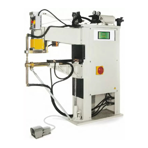
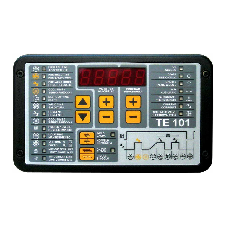
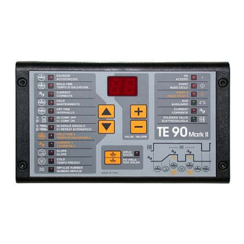
TECNA TE700 User manual

Instruction Manual ITEM TE700 TECNA S.p.A.
2/128
This page is intentionally left blank.

TECNA S.p.A. ITEM TE700 Instruction Manual
3/128
TABLE OF CONTENTS
CHAPTER 1 - TE700 WELDING CONTROL UNIT DESCRIPTION Pag. 6
1.1 - MAIN TECHNICAL FEATURES Pag. 7
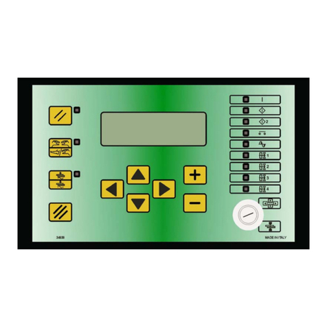
1.2 - PANEL CONTROLS Pag. 8
1.3 - PANEL LEDs Pag. 9
1.4 - DESCRIPTION OF DISPLAYED INFORMATION Pag. 10
1.5 - CONTROL UNIT SWITCH-ON Pag. 18
CHAPTER 2 - CONTROL UNIT PROGRAMMING Pag. 20
2.1 - PROGRAM DATA Pag. 21
2.2 - CONSTANT CURRENT OPERATING MODE Pag. 23
2.3 - FIX OPERATING MODE Pag. 27
2.4 - CONSTANT SECONDARY VOLTAGE OPERATING MODE Pag. 31
2.5 - CONSTANT POWER OPERATING MODE Pag. 34
2.6 - CONSTANT ENERGY OPERATING MODE Pag. 37
2.7 - DYINAMIC COMPENSATION OPERATING MODE Pag. 41
2.8 - WORKING PROGRAM PARAMETERS DESCRIPTION Pag. 44
2.9 -SETUP MENU Pag. 54
2.10 -STEPPER MENU Pag. 57
2.11 - ADJUSTMENT STEPPER FUNCTION Pag. 61
2.12 - FEATURES TE700 Pag. 66
2.13 - FEATURES INVERTER Pag. 70
2.14 - PROGRAMS COPY Pag. 75
2.15 - CHECK INPUT – DIAGNOSTIC TE700 Pag. 77
2.16 - CHECK INPUT – DIAGNOSTIC INVERTER Pag. 78
2.17 - PROG. SEQUENCE Pag. 79
2.18 - THICKNESS SENSE Pag. 82
2.19 - TIP-DRESSING Pag. 86
CHAPTER 3 - SEAM WELD OPERATING MODE Pag. 91
CHAPTER 4 - CASCADE OPERATING MODE Pag. 97
CHAPTER 5 - THE WORK CYCLE Pag. 98
CHAPTER 6 - STOP BAD SPOTS Pag. 99

Instruction Manual ITEM TE700 TECNA S.p.A.
4/128
CHAPTER 7 - WELDS COUNTER FUNCTION Pag. 105
CHAPTER 8 - ESCRIPTION OF THE INTERFACE OUTPUTS Pag. 107
8.1 - WELD ERROR (WRONG) Pag. 107
8.2 - END CYCLE Pag. 108
8.3 - LOCK Pag. 108
CHAPTER 9 - SELECTING THE WORK PROGRAM THROUGH EXTERNAL
RECALLS
Pag. 109
CHAPTER 10 - DOUBLE STROKE FUNCTION Pag. 113
CHAPTER 11 – OPTIONS Pag. 114
11.1 - RS-232 SERIAL INTERFACE Pag. 114
11.2 - INTERFACE FOR PROPORTIONAL VALVE Pag. 116
CHAPTER 12 - DESCRIPTION OF THE SIGNALS ON THE TERMINAL
BOARD
Pag. 117
CHAPTER 13 - LIST OF TE700 MESSAGES Pag. 120
13.1 - SYSTEM ERRORS – TE700 Pag. 120
13.2 - SYSTEM ERRORS - INVERTER Pag. 121
13.3 - WORK ERRORS Pag. 124
CHAPTER 14 – TECHNICAL SPECIFICATIONS Pag. 126

TECNA S.p.A. ITEM TE700 Instruction Manual
This page intentionally left blank.
The information contained in this document is subject to modification without prior notice.
No part of this document can be either reproduced or transferred in whatever format neither by electronic nor by
mechanic means for whatever purpose, without TECNA’s written permission. TECNA is a registered brand.
5/128

Instruction Manual ITEM TE700 TECNA S.p.A.
6/128
CHAPTER 1 – TE700 WELDING CONTROL UNIT DESCRIPTION
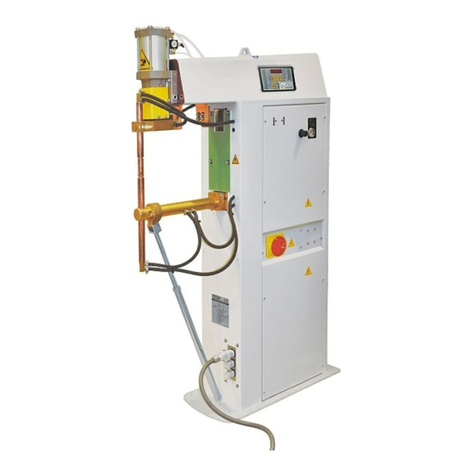
The TE700 is a microprocessor-based welding control unit for resistance welders equipped
with inverter technology. The task of the welding control unit is to manage the components of
the welder, specifically the IGBT power unit that adjusts the welding current.
The TE700 is a particularly versatile control unit since it can be adapted to different types of
welders. In addition to the spot and projection welders, it may also be installed on seam
welders and work with constant current, FIX, constant power, constant voltage, constant
energy adjustment and in dynamic mode. The number of the inputs and outputs may be
increased to better adapt the welding control unit to automatic machines.
The control unit can manage up to max 4 different welding transformers.
It is possible to store up to 300 different welding programs, 255 of which are recalled directly
from an external device. An alphanumeric identifier may be associated with each program to
simplify its identification. Each program comprises several programmable parameters that
describe the work cycle. In addition to the plain 4-stage welding cycle, the control unit allows
the running of welding processes with pre-welding current, post-welding current, slope and
pulses.

TECNA S.p.A. ITEM TE700 Instruction Manual
7/128
1.1 – MAIN TECHNICAL FEATURES
Simplified programming via 6 keys and a backlit alphanumeric LCD.
Inverter command with medium frequency IGBT, with possibility of choosing the operating
frequency of the inverter between 1000 Hz and 4000 Hz.
Storage of up to 300 welding programs; 255 may be called from external devices.
Possibility of associating an 8-character alphanumeric identifier with each weld program.
Possibility of managing as many as 4 different welding transformers or one transformer and 4
different types of electrodes.
Overheating protection for the welding transformers.
Up to 32 programmable parameters for each program.
Slope up, Slope down, pulses, pre-weld, post-weld functions and adjustment of the welding times
with units of 1 mS.
Display of the RMS of the welding current, energy, power, RMS of voltage to the electrodes, of the
initial and final resistance, of the machine's thermal use percentage, of the machine's use
percentage and, as an option, of the initial thickness of the welded material and the indentation at
the end of the weld.
6 WORKING MODEs: conventional, constant current, constant power, constant voltage, FIX,
constant energy, DYNAMIC mode.
Limit indicators for: Current, voltage at the electrodes, energy, power, inverter use percentage,
initial and final resistance of the material to be welded; thickness and indentation limit of the
material (optional).
Double stroke function.
Stepper function to compensate the wear and tear of the electrodes with programmable curves and
possibility of intervening independently on the time and the welding current through differentiated
stepper laws. Possibility of using 4 different stepper options associated with 4 different spot
counters associated with each weld program.
Single and automatic cycle. WELD and NO-WELD function.
Control of 5 solenoid valves 24 VDC max. 5 W with self-protected output.
Self-adjustment to the mains frequency 50/60 Hz.
Serial communication with insulated RS232 as an option.
Output for proportional solenoid valve.
Key for selecting foot control or two-hand control.
Selectable languages: Italian, English, French, German, Spanish, Hungarian, Swedish or
Portuguese.
Possibility of upgrading control unit Firmware via appropriate software.
Electrode tip dressing for up to max of 4 different spot counters (optional).

Instruction Manual ITEM TE700 TECNA S.p.A.
8/128
1.2 – PANEL CONTROLS
Left-hand direction key used for exiting from the programming menus.
Right-hand direction key used for entering the programming menus.
Upward direction key used for moving the cursor inside the upper
parameter.
Downward direction key used for moving the cursor inside the lower
parameter.
This key is used for increasing the value of a numeric parameter or
for changing the status of a parameter.
This key is used for decreasing the value of a numeric parameter or
for changing the status of a parameter.
RESTART key. It enables the commands and the outputs
of the control unit. Must be activated each time the
control unit is powered on. When this key is pressed, the
devices connected to the VAUX are powered and the
charge of the inverter capacitors is activated. Before
pressing this key check that the devices connected to
the VAUX cannot injure people or damage equipment.
Key for selecting the start cycle device: PEDAL or TWO-HANDS
CONTROL. When the nearby LED is switched off, the start cycle
command is carried out by the PEDAL whereas if the LED is switched
on, the command is carried out by the two-hand push buttons (TWO-
HANDS CONTROL). In order to work properly, the two push buttons
must be pressed at the same time or in sequence within a maximum
time of 0.5 seconds.
WELD-NO WELD Key.
In WELD position (LED switched on) the control unit runs the
programmed welding cycle. In NO-WELD position (LED switched off),
the control unit runs the programmed cycle without welding current
circulation keeping all the time parameters unchanged.
CLEAR Key. It is used to clear the error conditions and to set to zero
the weld counter.
PROG-RUN Key selector. In PROG position it enables the keyboard
and allows the running of all the foreseen programming operations. In
RUN start position it enables the spot welder commands and allows
the running of the work program only.

TECNA S.p.A. ITEM TE700 Instruction Manual
1.3 – PANEL LEDs
The turning on of this LED indicates that the welder control unit is
powered.
The turning on of this LED indicates that start cycle 1 command is
activated.
The turning on of this LED indicates that start cycle 2 command is
activated.
The turning on of this LED indicates that the pressure-only stopping
command by means of the AUX1 and AUX2 inlets is activated.
The turning on of this LED indicates that the control unit is generating the
command signal for the inverter welding unit.
It indicates that the solenoid valve, which carries out the main cycle, is
activated.
It indicates that the solenoid valve, which controls the back pressure, is
activated.
It indicates that the solenoid valve, which enables the forging, is
activated.
It indicates that the solenoid valve, which controls the double stroke, is
activated.
9/128

Instruction Manual ITEM TE700 TECNA S.p.A.
10/128
1.4 – DESCRIPTION OF DISPLAYED INFORMATION
Main work screen
The main screens display some information after every run weld cycle, both for cycles carried
out in weld mode, with the control unit set to WELD mode, and for cycles carried out in NO
WELD mode. The values displayed in the following description are for reference only.
PRG 005-FE ZN 10-01
WELD 0010mS E 00100J
IRMS 020.26 kA
SPOT 56002 r 055.4%
In WORK configuration, the displayed descriptions are always in English regardless of the
language selected in the SETUP MENU.
PRG 005-FE ZN 10-01
005 indicates the program used to carry out the last weld; the number may range from 001 to
300. It is displayed both in WELD and NO WELD mode.
FE ZN 10 is the alphanumeric identifier associated with the selected weld program. These are
8 characters that are defined at will by the operator to better identify the weld program. It is
displayed both in WELD and NO WELD mode.
01 is the identifier of the number of the tool used to carry out the weld. The number ranges
from 1 to 4. Displayed in WELD and NO WELD mode.
SPOT 56002
This is the counter that counts the carried out welds; the number may range from 00000 to
65000.
Each equipment is fitted with its own standalone spot counter that increases only when welds
are carried out through a program in which the equivalent tool number is set.
It is updated in WELD mode only and reset through the CLEAR key.
The following screen is displayed on pressing the CLEAR key:
CLEAR COUNTER
UP / DN TO SELECT:
RESET COUNTER T1?
<+> = OK <-> = CANCEL
Use keys and to select which of the four spot counters is to be reset or if all 4 are to be
reset at the same time. The number of the spot counters that are to be used depends on the
number of tools enabled inside the FEATURES INVERTER menu.Press key to reset the
selected counters or key to cancel the counter's deletion procedure.
WELD 0010mS
It indicates the weld time with which the last weld was carried out. The value ranges from
0001 to 9999. The same value is displayed both in WELD mode and in NO WELD mode.

TECNA S.p.A. ITEM TE700 Instruction Manual
IRMS 020.26kA
It indicates the value of the current with which the last weld was carried out. In WELD mode
the value may range from 000.00 kA to 200.00 kA. In NO WELD mode the value is 000.00 kA.
It represents the average of the RMS values measured for each weld time millisecond. The
displayed value always refers to the main adjustment that is to say to that of the WELD
parameter. In the case of pulse welds, the displayed current value is the average of the RMS
values of the current supplied during the single pulses.
E 00100J
It indicates the value of the energy supplied during the welding operation. The displayed value
always refers to the energy supplied inside the weld's main block. In the case of the pulse
adjustment, the displayed value always refers to the last run pulse. The value is updated if the
control unit is in WELD mode, if the control unit is in NO WELD mode, 00000J is displayed.
The display of -----J indicates that the configuration of the set machine does not permit
measuring the energy.
r 055.4%
It indicates the use percentage of the welding unit (transformer + inverter). The displayed
number is directly proportional to the welding unit capacity of supplying current. Approaching
100% means approaching the max current the machine can supply. This value will depend on
the type of welding unit, the geometry of the machine and the features of the material to be
welded. Approaching 100% entails a loss of the control unit's current adjustment capacities.
The value is updated in WELD mode. 000.0% is displayed in NO WELD mode.
Use keys and inside this screen to view data relevant to the previously carried out 20
weld spots. The control unit only stores data relevant to spots carried out in WELD mode. The
execution of a weld in WELD mode and in NO WELD mode leads to the display of data
relevant to the last spot carried out in WELD mode.
Other screens containing information about the weld cycle carried out can be viewed by
pressing key in the main work screen.
Sequence screen
The sequence screen may be accessed only in case the sequence function has been enabled
inside the control unit.
PRG 005-FE ZN 10-01
ST 001-020 NXTPR 024
WELD 2048 RMS 010.00
SPOT 02345 r 000.0
PRG 005-FE ZN 10-01
005 Indicates the program used to carry out the last weld. The number ranges from 001 to
300. It is displayed both in WELD and NO WELD mode.
FE ZN 10 is the alphanumeric identifier associated with the selected weld program. These are
8 characters that are defined at will by the operator to better identify the weld program. It is
displayed both in WELD and NO WELD mode.
01 is the identifier of the number of the transformer used to carry out the weld or the number
of the tool used. The number ranges from 1 to 4. It is displayed both in WELD and NO WELD
mode.
11/128

Instruction Manual ITEM TE700 TECNA S.p.A.
12/128
ST 001-020
001 Indicates the current spot inside the set welding sequence.
020 Indicates the total number of weld spots that make the sequence up.
The indication of the number of the spot inside the sequence increases both in WELD mode
and in NO WELD mode.
Use keys and to increase or decrease the present position inside the sequence so that
certain steps may be repeated or skipped.
NXTPR 024
It indicates the program with which the next spot will be carried out. The value is updated both
in WELD mode and in NO WELD mode.
WELD 2048
It indicates the weld time with which the last weld was carried out. The value ranges from
0001 to 9999. The same value is displayed both in WELD mode and in NO WELD mode.
RMS 010.00
It indicates the value of the current with which the last weld was carried out. In WELD mode
the value may range from 000.00 kA to 200.00 kA. In NO WELD mode the value is 000.00 kA.
It represents the average of the RMS values measured for every welding time millisecond.
The displayed value always refers to the main adjustment, that is to say to that of the WELD
parameter. If welding is by pulses, the current value is always the value of the last pulse
carried out.
SPOT 02345
It stands for the welded spots counter; it may be a number between 00000 and 65000. It is
updated in WELD mode only and it may be cleared by means of the CLEAR key.
r 000.0%
It indicates the use percentage of the welding unit (transformer + inverter). The displayed
number is directly proportional to the welding unit capacity of supplying current. Approaching
100% means approaching the max current the machine can supply. This value will depend on
the type of welding unit, the geometry of the machine and the features of the material to be
welded. Approaching 100% entails a loss of the control unit's current adjustment capacities.
The value is updated in WELD mode, 000.0% is displayed in NO WELD mode.
Weld analysis screen – 1
This screen may always be accessed regardless of the control unit's configuration.
PRG 005-FE ZN 10-01
POWER 000.0KW
VE 05.00V Th 083.0%
Rend 1285.0uOhm
PRG 005-FE ZN 10-01
005 Indicates the program used to carry out the last weld. The number ranges from 001 to
300. It is displayed both in WELD and NO WELD mode.

TECNA S.p.A. ITEM TE700 Instruction Manual
FE ZN 10 is the alphanumeric identifier associated with the selected weld program. These are
8 characters that are defined at will by the operator to better identify the weld program. It is
displayed both in WELD and NO WELD mode.
01 is the identifier of the number of the transformer used to carry out the weld or the number
of the tool used. The number ranges from 1 to 4. It is displayed both in WELD and NO WELD
mode.
POWER 000.0KW
It indicates the average value of the power supplied during the weld's main block. The value is
updated when the control unit is in WELD mode whilst 000.0KW is displayed when the unit is
in NO WELD mode. The display of ---.-KW means that the present configuration of the control
unit does not allow viewing the supplied power value. The displayed value always refers to
the energy supplied inside the weld's main block and in the case of the pulse WORKING
MODE it always refers to the last pulse.
VE 05.00V
It indicates the average value of the RMS voltage at the electrodes carried out every
millisecond. The value is updated when the control unit is in WELD mode whilst 00.00V is
displayed when the control unit is in NO WELD mode. The display of --.—V means that the
present configuration of the control unit does not allow viewing the electrodes voltage value.
The displayed value always refers to the energy supplied inside the weld's main block and in
the case of the pulse WORKING MODE it always refers to the last pulse.
Use keys and inside this screen to view data relevant to the previously carried out 20
weld spots. The control unit only stores data relevant to spots carried out in WELD mode. The
execution of a weld in WELD mode and in NO WELD mode leads to the display of data
relevant to the last spot carried out in WELD mode.
Weld analysis screen – 2
This screen may be accessed when the programming of at least one of the following
parameters has been activated inside the control unit: pre-weld, weld 2 or post weld.
PRG 005-FE ZN 10-01
PRE 0000mS 000.00KA
POST 0000mS 000.00KA
W2 0000mS 000.00KA
PRG 005-FE ZN 10-01
005 Indicates the program used to carry out the last weld. The number ranges from 001 to
300. It is displayed both in WELD and NO WELD mode.
FE ZN 10 is the alphanumeric identifier associated with the selected weld program. These are
8 characters that are defined at will by the operator to better identify the weld program. It is
displayed both in WELD and NO WELD mode.
01 is the identifier of the number of the transformer used to carry out the weld or the number
of the tool used. The number ranges from 1 to 4. It is displayed both in WELD and NO WELD
mode.
PRE 0000mS 000.00KA
It indicates the duration in mS and the RMS welding current average during the pre-weld
block.
13/128

Instruction Manual ITEM TE700 TECNA S.p.A.
14/128
The time value is displayed both in WELD mode and in NO WELD mode. The value of the
current is displayed only in WELD mode whilst 000.00KA is displayed in NO WELD mode.
If PRE ----mS ---.—KA is displayed, this means that the programming of the pre-weld
parameter is disabled inside the control unit.
POST 0000mS 000.00KA
It indicates the duration in mS and the RMS welding current average during the post-weld
block.
The time value is displayed both in WELD mode and in NO WELD mode. The value of the
current is displayed only in WELD mode whilst 000.00KA is displayed in NO WELD mode.
If POST ----mS ---.—KA is displayed, this means that the programming of the post-weld
parameter is disabled inside the control unit.
W2 0000mS 000.00KA
It indicates the duration in mS and the RMS welding current average during the weld 2 block.
The time value is displayed both in WELD mode and in NO WELD mode. The value of the
current is displayed only in WELD mode whilst 000.00KA is displayed in NO WELD mode.
If W2 ----mS ---.—KA is displayed, this means that the programming of the weld 2 parameter
is disabled inside the control unit.
Use keys and inside this screen to view data relevant to the previously carried out 20
weld spots. The control unit only stores data relevant to spots carried out in WELD mode. The
execution of a weld in WELD mode and in NO WELD mode leads to the display of data
relevant to the last spot carried out in WELD mode.
Stepper analysis screen
This screen may be accessed only if the stepper function is activated on the control unit.
PRG 005-FE ZN 10-01
STEP 1-7 SPOT 02400
INC1 001.0 % OF 060%
INC2 023.1 % OF 030%
PRG 005-FE ZN 10-01
005 Indicates the program used to carry out the last weld. The number ranges from 001 to
300. It is displayed both in WELD and NO WELD mode.
FE ZN 10 is the alphanumeric identifier associated with the selected weld program. These are
8 characters that are defined at will by the operator to better identify the weld program. It is
displayed both in WELD and NO WELD mode.
01 is the identifier of the number of the transformer used to carry out the weld or the number
of the tool used. The number ranges from 1 to 4. It is displayed both in WELD and NO WELD
mode.
STEP 1-7
It indicates the control unit's present STEP and the total number of STEPS activated on the
stepper’s parameterization. The datum increases only when the control unit is in WELD mode
and does not increase when the unit is in NO WELD mode.

TECNA S.p.A. ITEM TE700 Instruction Manual
SPOT 02400
It indicates the number of the present spot. The counter increases when the control unit is in
WELD mode and does not increase when the unit is in NO WELD mode.
INC1 001.0 % 0F 060%
It indicates the present percentage increase of the quantity associated with stepper law 1 and
the final increment of the same quantity at the end of the present STEP.
If INC 1 000.0 % OF 000 % is displayed, this means that no quantity is present associated
with stepper law 1 or that a percentage increase of 0% has been associated with this quantity.
The value is not updated when the control unit is in NO WELD mode.
INC2 023.1 % OF 030 %
It indicates the present percentage increase of the quantity associated with stepper law 2 and
the final increment of the same quantity at the end of the present STEP.
If INC 2 000.0% OF 000 % is displayed, this means that no quantity is present associated
with stepper law 2 or that a percentage increase of 0% has been associated with this quantity.
The value is not updated when the control unit is in NO WELD mode.
Use keys and inside this screen to view data relevant to the previously carried out 20
weld spots. The control unit only stores data relevant to spots carried out in WELD mode. The
execution of a weld either in WELD mode or in NO WELD mode entails the display of the data
relevant to the last spot carried out in WELD mode.
Electrodes dressing analysis screen
This screen may be accessed only if the dressing function (optional) is activated on the
control unit.
PRG 005-FE ZN 10-01
SOT 00001
INC DRESS 01%
DRESSING -00500
PRG 005-FE ZN 10-01
005 Indicates the program used to carry out the last weld. The number ranges from 001 to
300. It is displayed both in WELD and NO WELD mode.
FE ZN 10 is the alphanumeric identifier associated with the selected weld program. These are
8 characters that are defined at will by the operator to better identify the weld program. It is
displayed both in WELD and NO WELD mode.
01 is the identifier of the number of the transformer used to carry out the weld or the number
of the tool used. The number ranges from 1 to 4. It is displayed both in WELD and NO WELD
mode.
SPOT 00001
It indicates the number of the present spot. The counter increases when the control unit is in
WELD mode and does not increase when the unit is in NO WELD mode.
INC DRESS 01%
It indicates the percentage increase of the weld parameter inside the present electrodes
dressing STEP. The value does not increase when the unit is in NO WELD mode.
15/128

Instruction Manual ITEM TE700 TECNA S.p.A.
16/128
DRESSING – 00500
It indicates the remaining number of weld spots before the need to carry out the electrodes'
dressing or changing operations. The counter does not decrease when the control unit is in
NO WELD mode.
Use keys and inside this screen to view data relevant to the previously carried out 20
weld spots. The control unit only stores data relevant to spots carried out in WELD mode. The
execution of a weld either in WELD mode or in NO WELD mode entails the display of the data
relevant to the last spot carried out in WELD mode.
Quality analysis screen
This screen may be accessed only when the quality control function is enabled in the control
unit by measuring the resistance of the material to be spot welded or by measuring the
thickness of the material in between the electrodes.
PRG 005-FE ZN 10-01
IDENT. 00.000mm
THICK. 00.000mm
R START 0000.0uOhm
PRG 005-FE ZN 10-01
005 Indicates the program used to carry out the last weld. The number ranges from 001 to
300. It is displayed both in WELD and NO WELD mode.
FE ZN 10 is the alphanumeric identifier associated with the selected weld program. These are
8 characters that are defined at will by the operator to better identify the weld program. It is
displayed both in WELD and NO WELD mode.
01 is the identifier of the number of the transformer used to carry out the weld or the number
of the tool used. The number ranges from 1 to 4. It is displayed both in WELD and NO WELD
mode.
IDENT. 00.000MM
It indicates the measurement of the electrode penetration into the material at the end of the
welding procedure.
If this function is disabled, 00.000mm is displayed. The value is updated both in WELD mode
and in NO WELD mode.
THICK. 00.000mm
It indicates the initial thickness of the material to be welded. The measurement is carried out
before the current passage. If this function is not enabled, 00.000mm is displayed.
The value is updated both in WELD mode and in NO WELD mode.
R START 0000.0uOhm
It indicates the initial value of the resistance of the material to be spot welded. The value is
updated only when the control unit is in WELD mode.
Use keys and inside this screen to view data relevant to the previously carried out 20
weld spots. The control unit only stores data relevant to spots carried out in WELD mode. The
execution of a weld either in WELD mode or in NO WELD mode entails the display of the data
relevant to the last spot carried out in WELD mode.

TECNA S.p.A. ITEM TE700 Instruction Manual
Errors log screen
The errors log screen is always accessible and contains information about the last 20 errors
signalled by the control unit.
ERR: 162 INVERTER
SPOT: 00001 LOG: 05
DRESSING [165]
CAPS NEED DRESSING
ERR: 162
This is the code of the error displayed.
INVERTER
It indicates if the error originated from the INVERTER or the TE700 control unit.
SPOT: 00001
It indicates the value of the spot counter when the signalled error occurred.
LOG: 05
It indicates the position of the error inside the LOG. The value may range from 1 to 20. The
highest number refers to the last error that occurred whilst the lowest number indicates the
oldest error.
DRESSING [165] / CAPS NEED DRESSING
Concise description of the displayed error. For further information consult this manual.
Use keys and inside this screen to scroll through the list of errors saved inside the
control unit. Press the + key to scroll through the list of most recent errors or the – key to
scroll through the list of the earliest errors.
17/128

Instruction Manual ITEM TE700 TECNA S.p.A.
18/128
1.5 – CONTROL UNIT SWITCH-ON
As soon as the control unit is switched on, the display notifies the operator that the
communication interface is initializing.
CAN INTERFACE
INIT
After the initialization of the communication interface, the control unit checks for the integrity
of the communication channel with the inverter. The following wait message is displayed until
the check is finished:
INVERTER COM CAN-BUS
NOT READY WAIT..
The following message is displayed once the working efficiency of the communication channel
has been checked.
INVERTER COM CAN-BUS
READY
Next, the mains frequency recognized by the control unit is displayed.
MAINS FREQUENCY
50 Hz
Both the type of control unit and the relevant software version are displayed.
TE700 REV. 1.09
WELD CONTROL UNIT
In order to complete the control unit switch-on sequence, the operator is asked to press the
RESTART button or to generate the RESTART sequence through external program recalls.
The displayed message is as follows.
PRESS RESTART
BUTTON [//]

TECNA S.p.A. ITEM TE700 Instruction Manual
This RESTART button enables the control unit's commands and outputs. It must be pressed
every time the control unit is powered.
As soon as the RESTART command is issued, all the devices connected to the VAUX output
are supplied and the charging procedure for the capacitors bank is started on the inverter.
Before activating the RESTART command, it is important to check
that it will not cause damage to people or equipment.
The following message is displayed until the inverter is ready to weld.
INVERTER CAPACITOR
CHARGING PLEASE WAIT
Before starting any welding operations, first program the welding data and set some general
operating parameters of the welder.
For safety reasons, the microprocessor does not start the welding
cycle if the cycle start signal is actuated when the welder is turned
on. Simply release the control and actuate it again. Micro-cutoffs or
excessive voltage drops do not alter the control unit's working
efficiency but stop it. To restore working efficiency, turn off the
machine and then turn it on again.
19/128

Instruction Manual ITEM TE700 TECNA S.p.A.
20/128
CHAPTER 2 – CONTROL UNIT PROGRAMMING
By placing the key in PROGRAM DATA position the following screen is displayed:
-TE700 VER. 1.09 --
>PROGRAM DATA
SETUP MENU
STEPPER MENU
The first row reports the control unit type and the software version. Then the display lists all
the menus allowing accessing the various control unit functions.
The following list includes all the menus available in the control unit. However, it is
possible that not all of these menus are displayed by the control unit being used as
some of them depends either on the options actually inserted in the control unit or on
the welder type the control unit is installed onto.
_ PROGRAM DATA
_ SETUP MENU
_ STEPPER MENU
_ FEATURES TE700
_ FEATURES INVERTER
_ PROGRAM COPY
_ DIAGNOSTIC TE700
_ DIAGNOSTIC INV.
_ PROG. SEQUENCE
_ THICKNESS SENSE (It may be activated)
_ TIP-DRESSING (It may be activated)
-TE700 VER. 1.09 --
PROGRAM DATA
>SETUP MENU
STEPPER MENU
Use keys and to move up and down the > arrow cursor displayed on the left-hand side
of the menus. Use keys and to enter and exit from the menu selected by the cursor.
Use keys and to modify the parameter indicated by the cursor.
PROGRAM DATA T1
PROGRAM N. 001
>PRG. NAME
TOOLS N° 1
Table of contents
Other TECNA Welding System manuals