TECNA 7911 User manual

Art. 7911 PUNTATRICE PNEUMATICA 2,5 kVA CON TIMER INCORPORATO A SCR E COMPENSAZIONE
Art. 7911P PUNTATRICE PNEUMATICA 2,5 kVA CON TIMER A SCR, COMPENSAZIONE E PULSAZIONI
Art. 7913 PUNTATRICE PNEUMATICA GIROSCOPICA 6 kVA RAFFREDDATA AD ACQUA CON TIMER A SCR E
COMPENSAZIONE
Art. 7913P PUNTATRICE PNEUMATICA GIROSCOPICA 6 kVA RAFFREDDATA AD ACQUA CON TIMER A SCR,
COMPENSAZIONE E PULSAZIONI
Art. 7915 PUNTATRICE PNEUMATICA 6 kVA RAFFREDDATA AD ACQUA CON TIMER A SCR E COMPENSAZIONE
Art. 7915P PUNTATRICE PNEUMATICA 6 kVA RAFFREDDATA AD ACQUA CON TIMER A SCR, COMPENSAZIONE E
PULSAZIONI
Item 7911 AIR OPERATED SPOT WELDER 2,5 KVA WITH SCR TIMER AND COMPENSATION
Item 7911P AIR OPERATED SPOT WELDER 2,5 WITH SCR TIMER, COMPENSATION AND PULSES
Item 7913 AIR OPERATED GYROSCOPIC SPOT WELDER 6 KVA WITH SCR TIMER AND COMPENSATION, WATER
COOLED
Item 7913P AIR OPERATED GYROSCOPIC SPOT WELDER 6 KVA WITH SCR TIMER, COMPENSATION AND PULSES,
WATER COOLED
Item 7915 AIR OPERATED SPOT WELDER 6 KVA WITH SCR TIMER AND COMPENSATION, WATER COOLED
Item 7915P AIR OPERATED SPOT WELDER 6 KVA WITH SCR TIMER, COMPESATION AND PULSES, WATER COOLED
Art. 7911 PINCE A SOUDER PNEUMATIQUE 2,5 KVAAVEC TEMPORISATEUR ATHYRISTORS ET CONTROLE D’ENERGIE
Art. 7911P PINCE A SOUDER PNEUMATIQUE 2,5 KVA AVEC TEMPORISATEUR A THYRISTORS, CONTROLE D’ENERGIE
ET PULSATIONS
Art. 7913 PINCE A SOUDER PNEUMATIQUE GYROSCOPIQUE 6 KVA AVEC TEMPORISATEUR A SCR ET CONTROLE
D’ENERGIE, REFROIDIE PAR EAU
Art. 7913P PINCE A SOUDER PNEUMATIQUE GYROSCOPIQUE 6 KVA AVEC TEMPORISATEUR A SCR, CONTROLE
D’ENERGIE ET PULSATIONS, REFROIDIE PAR EAU
Art. 7915 PINCE A SOUDER PNEUMATIQUE 6 KVA AVEC TEMPORISATEUR A SCR ET CONTROLE D’ENERGIE,
REFROIDIE PAR EAU
Art. 7915P PINCE A SOUDER PNEUMATIQUE 6 KVA AVEC TEMPORISATEUR A SCR, CONTROLE D’ENERGIE ET
PULSATIONS, REFROIDIE PAR EAU
Art. 7911 PNEUMATISCHE PUNKTSCHWEISSZANGE 2,5 KVA MIT THYRISTORGESTEUERTEM ZEITGEBER UND
KOMPENSATION
Art. 7911P PNEUMATISCHE PUNKTSCHWEISSZANGE 2,5 KVA MIT THYRISTORGESTEUERTEM ZEITGEBER,
KOMPENSATION UND PULSE
Art. 7913 PNEUMATISCHE PUNKTSCHWEISSZANGE 6 KVA MIT THYRISTORGESTEUERTEM ZEITGEBER UND
KOMPENSATION, KREISELAUFHÄNGUNG, WASSERGEKÜHLT
Art. 7913P PNEUMATISCHE PUNKTSCHWEISSZANGE 6 KVA MIT THYRISTORGESTEUERTEM ZEITGEBER,
KOMPENSATION UND PULSE, KREISELAUFHÄNGUNG, WASSERGEKÜHLT
Art. 7915 PNEUMATISCHE PUNKTSCHWEISSZANGE 6 KVA MIT THYRISTORGESTEUERTEM ZEITGEBER UND
KOMPENSATION, WASSERGEKÜHLT
Art. 7915P PNEUMATISCHE PUNKTSCHWEISSZANGE 6 KVA MIT THYRISTORGESTEUERTEM ZEITGEBER,
KOMPENSATION UND PULSE, WASSERGEKÜHLT
Art. 7911 PUNTATRIZ NEUMATICA 2,5 KVA CON TEMPORIZADOR A SCR Y COMPENSACION
Art. 7911P PUNTATRIZ NEUMATICA 2,5 KVA CON TEMPORIZADOR A SCR, COMPENSACION Y PULSACIONES
Art. 7913 PUNTATRIZ NEUMATICA GIROSCOPICA 6 KVA CON TEMPORIZADOR A SCR Y COMPENSACION,
REFRIGERADA POR AGUA
Art. 7913P PUNTATRIZ NEUMATICA GIROSCOPICA 6 KVA CON TEMPORIZADOR A SCR, COMPENSACION Y
PULSACIONES, REFRIGERADA POR AGUA
Art. 7915 PUNTATRIZ NEUMATICA 6 KVA CON TEMPORIZADOR A SCR Y COMPENSACION, REFRIGERADA POR AGUA
Art. 7915P PUNTATRIZ NEUMATICA 6 KVA CON TEMPORIZADOR A SCR, COMPENSACION Y PULSACIONES,
REFRIGERADA POR AGUA
S.p.a. - Via Grieco 25/27 - 40024 Castel S. Pietro Terme - (BO) - ITALY
Pho +39.051.6954400 - Tel. 051.6954410 - Fax +39.051.6954490
http://www.tecna.net E-mail:[email protected] - [email protected]
DOCUMENTO NUMERO:
DOCUMENT NUMBER:
DOCUMENT NUMERO:
DOKUMENT NUMMER:
DOCUMENTO:
DISTRIBUTORE:
DISTRIBUTOR:
DISTRIBUTEUR:
VERTRIEB:
DISTRIBUIDOR:
EDIZIONE:
EDITION:
EDITION:
AUSGABE:
EDICION:
MAN 2006

2
Art. / Item 7911-7913-7915
INDICE
INTRODUZIONE .................................................................................................................................................................................. 5
DOTAZIONE DI SERIE ...................................................................................................................................................................................... 5
CARATTERISTICHE TECNICHE ....................................................................................................................................................................... 5
SIMBOLI DI RIFERIMENTO .............................................................................................................................................................................. 5
INSTALLAZIONE................................................................................................................................................................................................ 6
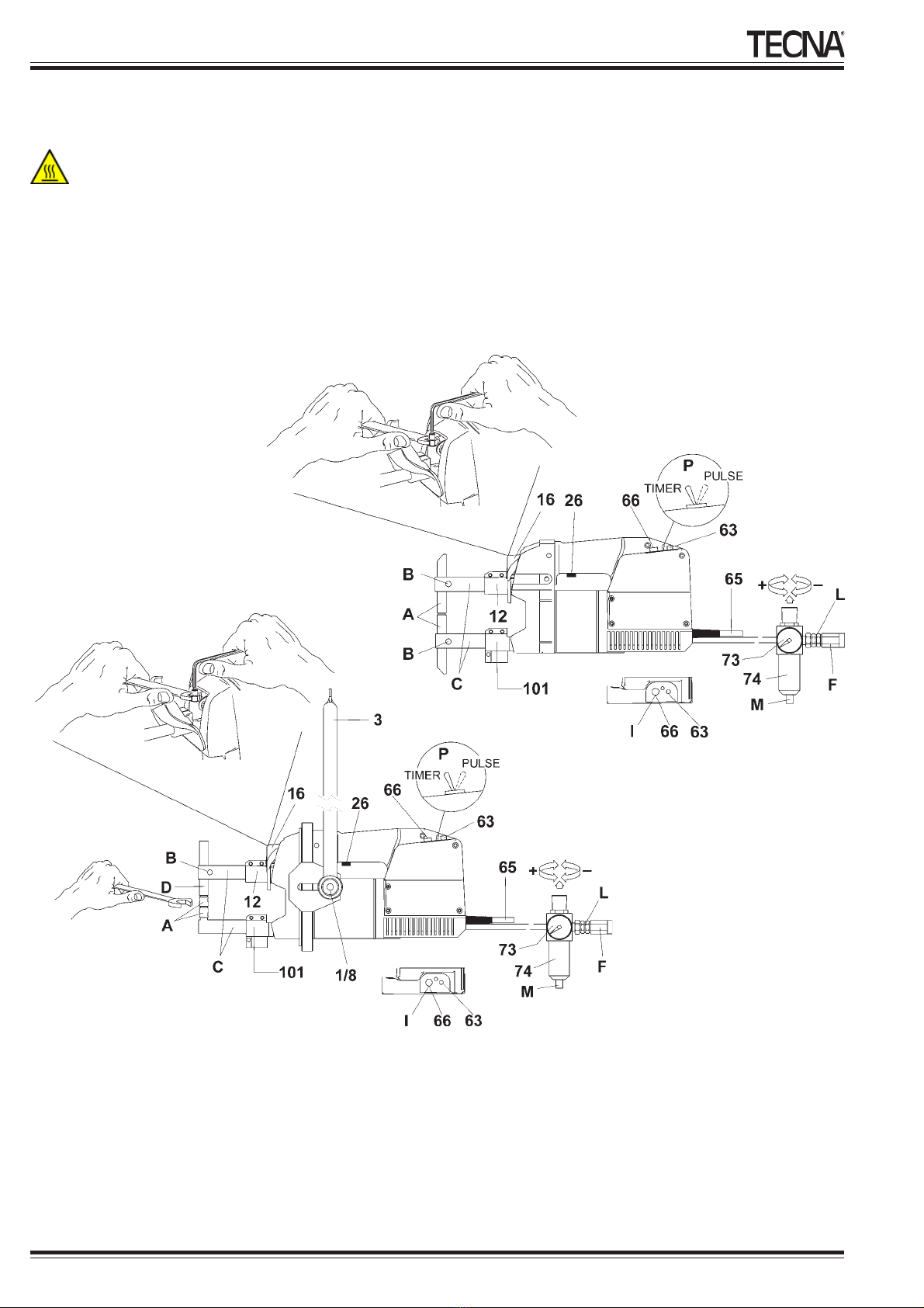
INSTALLAZIONE PNEUMATICA ....................................................................................................................................................................... 6
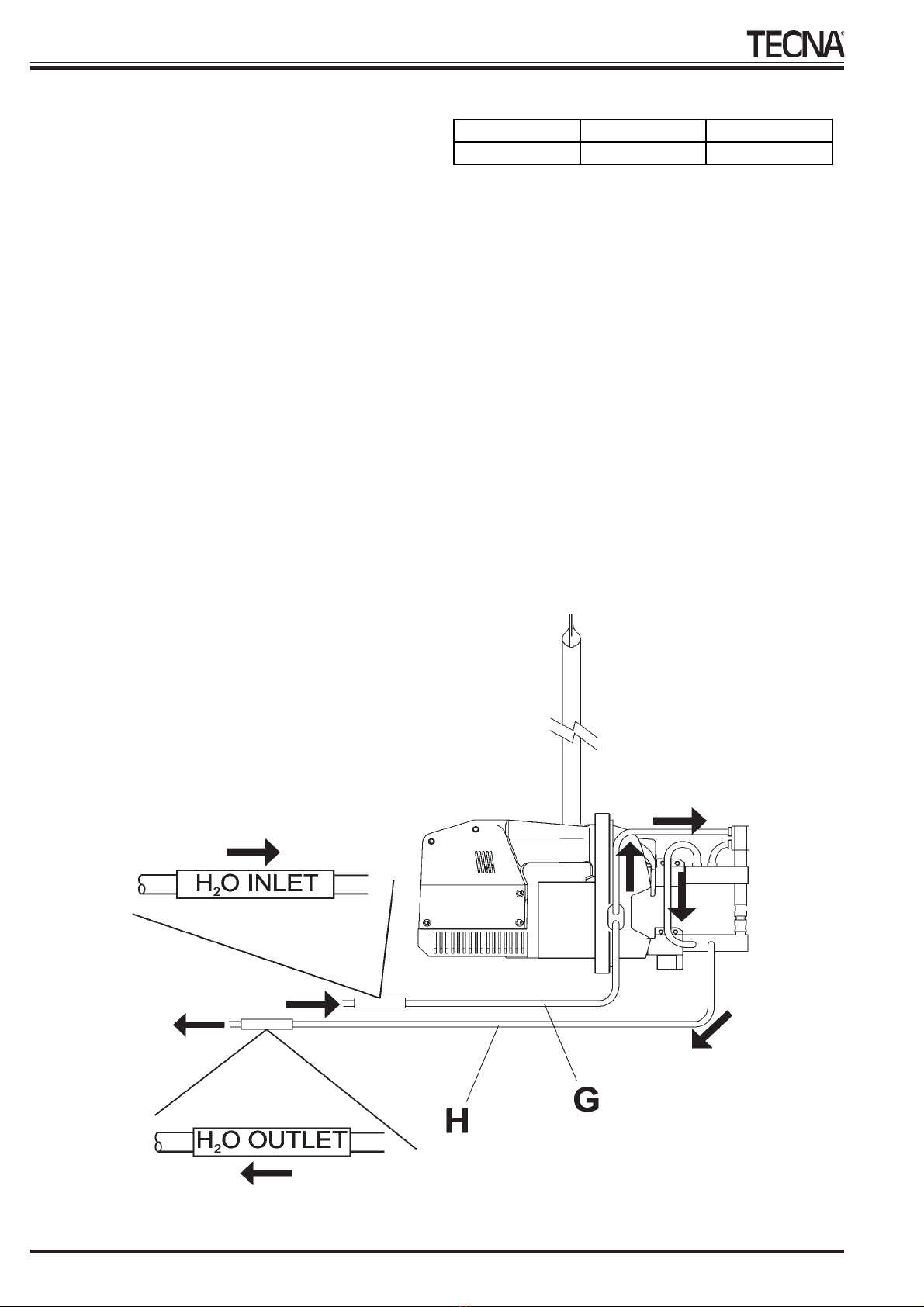
INSTALLAZIONE CIRCUITO DI RAFFREDDAMENTO (SOLO ART. 7913-7915) ............................................................................................. 6
INSTALLAZIONE DEL SISTEMA DI SOSPENSIONE (SOLO ART. 7913) ........................................................................................................ 7
INSTALLAZIONE ELETTRICA ........................................................................................................................................................................... 7
NORME DI SICUREZZA .................................................................................................................................................................................... 7
REGOLAZIONE E IMPIEGO ............................................................................................................................................................................. 9
Messa a punto dei bracci e degli elettrodi ......................................................................................................................................................... 9
Regolazione della forza agli elettrodi ................................................................................................................................................................. 9
Regolazione dei parametri di saldatura .............................................................................................................................................................. 9
LAVORO ............................................................................................................................................................................................................ 9
MANUTENZIONE............................................................................................................................................................................................... 9
MANUTENZIONE ORDINARIA .......................................................................................................................................................................... 9
GENERALI ......................................................................................................................................................................................................... 9
ELETTRODI ....................................................................................................................................................................................................... 9
CIRCUITO PNEUMATICO ................................................................................................................................................................................. 9
CIRCUITO DI RAFFREDDAMENTO (SOLO ART. 7913-7915) ......................................................................................................................... 9
CIRCUITO ELETTRICO ..................................................................................................................................................................................... 9
MANUTENZIONE STRAORDINARIA .............................................................................................................................................................. 10
SOLUZIONE DEI DIFETTI NELLA SALDATURA ............................................................................................................................................ 10
PARTI Dl RICAMBIO ........................................................................................................................................................................................ 10
MESSA A PUNTO DELLA PUNTATRICE ........................................................................................................................................................ 35
INTRODUCTION ................................................................................................................................................................................ 11
STANDARD ACCESSORIES ........................................................................................................................................................................... 11
TECHNICAL FEATURES ................................................................................................................................................................................. 11
REFERENCE SYMBOLS ................................................................................................................................................................................. 11
INSTALLATION ................................................................................................................................................................................................ 12
PNEUMATIC INSTALLATION .......................................................................................................................................................................... 12
COOLING CIRCUIT INSTALLATION (ONLY ITEMS 7913-7915) .................................................................................................................... 12
SUSPENSION SYSTEM INSTALLATION (ONLY ITEM 7913) ........................................................................................................................ 13
ELECTRICAL INSTALLATION ......................................................................................................................................................................... 13
SAFETY RULES .............................................................................................................................................................................................. 13
ADJUSTMENTS AND USE .............................................................................................................................................................................. 15
Arms and electrodes set up ............................................................................................................................................................................. 15
Electrode force adjustment .............................................................................................................................................................................. 15
Welding parameters adjustment ...................................................................................................................................................................... 15
WORK ............................................................................................................................................................................................................ 15
MAINTENANCE ............................................................................................................................................................................................... 15
ORDINARY MAINTENANCE ........................................................................................................................................................................... 15
GENERAL WARNINGS ................................................................................................................................................................................... 15
ELECTRODES ................................................................................................................................................................................................. 15
PNEUMATIC CIRCUIT ..................................................................................................................................................................................... 15
COOLING CIRCUIT (ON ITEMS 7913-7915 ONLY) ........................................................................................................................................ 15
ELECTRIC CIRCUIT ........................................................................................................................................................................................ 15
EXTRAORDINARY MAINTENANCE ............................................................................................................................................................... 16
REMEDIES FOR WELDS IMPERFECTIONS ................................................................................................................................................. 16
SPARE PARTS ................................................................................................................................................................................................. 16
ADJUSTING THE SPOT WELDER ................................................................................................................................................................. 35
INTRODUCTION ................................................................................................................................................................................ 17
FOURNITURE STANDARD ............................................................................................................................................................................. 17
CARACTERISTIQUES TECHNIQUES ............................................................................................................................................................ 17
SYMBOLES DE REFERENCE ........................................................................................................................................................................ 17
INSTALLATION ................................................................................................................................................................................................ 18
INSTALLATION PNEUMATIQUE ..................................................................................................................................................................... 18
INSTALLATION DU CIRCUIT DE REFROIDISSEMENT (POUR LES SEULS ART.7913-7915) ..................................................................... 18
INSTALLATION DU SYSTEME DE SUSPENSION (POUR LE SEUL ART. 7913) .......................................................................................... 19
INSTALLATION ELECTRIQUE ........................................................................................................................................................................ 19
NORMES DE SECURITE ................................................................................................................................................................................ 19
REGLAGE ET UTILISATION ........................................................................................................................................................................... 21
Réglage des bras et des électrodes ................................................................................................................................................................ 21
Réglage de la force aux électrodes ................................................................................................................................................................. 21
Réglage des paramètres de soudage .............................................................................................................................................................. 21
CONDITIONS DE TRAVAIL ............................................................................................................................................................................. 21
ENTRETIEN ..................................................................................................................................................................................................... 21
ENTRETIEN DE ROUTINE .............................................................................................................................................................................. 21
INFORMATIONS GENERALES ....................................................................................................................................................................... 21
ELECTRODES ................................................................................................................................................................................................. 21
CIRCUIT PNEUMATIQUE ................................................................................................................................................................................ 21
CIRCUIT DE REFROIDISSEMENT (POUR LES SEULS ART. 7913-7915) .................................................................................................... 21
CIRCUIT ELECTRIQUE ................................................................................................................................................................................... 21
ENTRETIEN EXTRAORDINAIRE .................................................................................................................................................................... 22
RESOLUTION DES DEFAUTS DANS LE SOUDAGE ..................................................................................................................................... 22
PIECES DETACHEES ..................................................................................................................................................................................... 22
REGLAGE DE LA SOUDEUSE PAR POINTS ................................................................................................................................................. 35

3
Art. / Item 7911-7913-7915
EINLEITUNG ...................................................................................................................................................................................... 23
STANDARDAUSRÜSTUNG ............................................................................................................................................................................. 23
TECHNISCHE DATEN ..................................................................................................................................................................................... 23
KENNSYMBOLE .............................................................................................................................................................................................. 23
ANSCHLUSS ................................................................................................................................................................................................... 24
PNEUMATISCHER ANSCHLUSS .................................................................................................................................................................... 24
ANSCHLUSS KÜHLUNG (NUR ART. 7913-7915) ........................................................................................................................................... 24
INSTALLIERUNG AUFHÄNGUNGSSYSTEM (NUR ART. 7913) ..................................................................................................................... 25
ELEKTRISCHER ANSCHLUSS ....................................................................................................................................................................... 25
SICHERHEITSBESTIMMUNGEN .................................................................................................................................................................... 25
EINSTELLUNG UND ANWENDUNG ............................................................................................................................................................... 27
Einstellung der Arme und Elektroden ............................................................................................................................................................... 27
Einstellung Elektrodenkraft .............................................................................................................................................................................. 27
Einstellung Schweissparameter ....................................................................................................................................................................... 27
ARBEIT ............................................................................................................................................................................................................ 27
WARTUNG ....................................................................................................................................................................................................... 27
NORMALE WARTUNG .................................................................................................................................................................................... 27
ALLGEMEINES ................................................................................................................................................................................................ 27
ELEKTRODEN ................................................................................................................................................................................................. 27
PNEUMATIK .................................................................................................................................................................................................... 27
KÜHLUNG (NUR ART. 7913-7915) .................................................................................................................................................................. 27
ELEKTRIK ........................................................................................................................................................................................................ 27
AUSSERPERIODISCHE WARTUNG .............................................................................................................................................................. 28
ABHILFE SCHWEISSDEFEKTE ..................................................................................................................................................................... 28
ERSATZTEILE ................................................................................................................................................................................................. 28
EINSTELLUNG DER PUNKTSCHWEIßZANGE .............................................................................................................................................. 35
INTRODUCCION ............................................................................................................................................................................... 29
DOTACION DE SERIE ..................................................................................................................................................................................... 29
CARACTERISTICAS TECNICAS .................................................................................................................................................................... 29
INSTALACION.................................................................................................................................................................................................. 30
INSTALACION NEUMATICA ............................................................................................................................................................................ 30
INSTALACION DEL CIRCUITO DE REFIGERACION (SOLO ART.7913-7915) .............................................................................................. 30
INSTALACION SISTEMA DE SUSPENSION (SOLO ART. 7913) ................................................................................................................... 31
INSTALACION ELECTRICA ............................................................................................................................................................................ 31
NORMAS DE SEGURIDAD ............................................................................................................................................................................. 31
REGLAJE Y EMPLEO ..................................................................................................................................................................................... 33
Puesta a punto de los brazos y electrodos ...................................................................................................................................................... 33
Reglaje de la fuerza a los electrodos .............................................................................................................................................................. 33
Reglaje de los parámetros de soldadura ......................................................................................................................................................... 33
TRABAJO ......................................................................................................................................................................................................... 33
MANTENIMIENTO ........................................................................................................................................................................................... 33
MANTENIMINENTO ORDINARIO ................................................................................................................................................................... 33
OPERACIONES GENERALES ........................................................................................................................................................................ 33
ELECTRODOS ................................................................................................................................................................................................ 33
CIRCUITO NEUMÁTICO ................................................................................................................................................................................. 33
CIRCUITO DE REFRIGERACIÓN (SOLO ART.7913-7915) ............................................................................................................................ 33
CIRCUITO ELECTRICO .................................................................................................................................................................................. 33
MANTENIMIENTO EXTRAORDINARIO .......................................................................................................................................................... 34
PIEZAS DE RECAMBIO .................................................................................................................................................................................. 34
PUESTA A PUNTO DE LA PINZA .................................................................................................................................................................... 35
TAVOLE PARTI DI RICAMBIO E DISTINTE - SPARE PARTS AND CHECKLISTS TABLES
PLANCHES DES PIECES DE RECHANGE ET NOMENCLATURES - ERSATZTEILLISTEN UND STÜCKLISTEN
TABLAS PIEZAS DE REPUESTO Y MARCAS ............................................................................................................................................... 39
Art. / Item 7911 - 7913 - 7915 .......................................................................................................................................................................... 40
Art. / Item 7911 - 7913 - 7915 .......................................................................................................................................................................... 41
Art. / Item 7911 - 7915 ..................................................................................................................................................................................... 42
Art. / Item 7913 ................................................................................................................................................................................................ 43
ACCESSORI - ACCESSORIES - ACCESSOIRES
ZUBEHÖRE - ACCESORIOS .......................................................................................................................................................................... 48

4
Art. / Item 7911-7913-7915
Pagina lasciata volutamente bianca a causa dell’impostazione grafica del manuale istruzioni
This page is left intentionally blank due to the graphic setting of the instruction manual
Page laissée intentionnellement blanche à cause de l’imposition graphique du manuel d’utilisation
Diese Seite wurde aus Gründen der grafischen Handbuchgestaltung absichlich leer gelassen
Página dejada intencionadamente en blanco por motivos de composición gráfica del manual de instrucciones

5
Art. / Item 7911-7913-7915
INTRODUZIONE
LEGGERE ATTENTAMENTE QUESTO MANUALE DI
ISTRUZIONE PRIMA DI INSTALLARE ED UTILIZZARE LA
SALDATRICE
Scopo di questo manuale, e dei documenti allegati, è la trasmissione
delle informazioni necessarie all'uso competente e sicuro del prodot-
to. Esso comprende informazioni inerenti la sicurezza, l'installazione,
l'uso, la manutenzione e lo smaltimento del prodotto.
Il presente manuale è indirizzato al responsabile di stabilimento
che lo deve rendere noto al personale addetto all'installazione,
all'uso e alla manutenzione della saldatrice. Si deve accertare
che le informazioni presentate in questo documento, e nei docu-
menti allegati, siano state lette e comprese prima di operare sulla
macchina. Il manuale deve essere conservato in luogo noto e
facilmente accessibile e deve essere consultato ogni qualvolta
sorgano anche piccoli dubbi.
Le saldatrici contraddistinte dal suffisso Psono dotate della mo-
dalità di funzionamento a pulsazioni comunque escludibile. La
pulsazione consiste nell’erogazione di potenza a intervalli rego-
lari. Al massimo è possibile eseguire 13 pulsazioni (5 cicli com-
pleti) intervallati da 2 cicli di pausa. La durata delle pulsazioni è
regolabile dalla manopola 66 (Fig.3).
Le saldatrici oggetto di questo manuale sono state progettate per es-
sere utilizzate solo a scopo professionale in ambiente industriale e
sono classificate come saldatrici a resistenza di classe A. Non è pre-
visto l'uso in ambiente domestico o su linee di alimentazione pubbli-
che a bassa tensione che alimentano edifici utilizzati a scopi domesti-
ci. Questo può causare interferenze di radiofrequenza.
Sono vietati interventi di modifica, anche se lievi, perché possono
compromettere la sicurezza della macchina e invalidano la
certificazione CE della stessa. Scopo della macchina è la salda-
tura a resistenza per punti di materiali ferrosi e non (acciaio inox,
ottone). La saldatrice non deve essere utilizzata per altri scopi.
La TECNA S.p.A. si esime da qualsiasi responsabilità per danni a
persone, animali, cose ed alla macchina stessa causati da un
impiego non corretto, dalla mancanza o superficiale osservanza
dei criteri di sicurezza riportati nel presente manuale, dalle
manomissioni anche lievi e dall'impiego di parti di ricambio e ac-
cessori non originali o non compatibili.
Solo per i Paesi della CE:
In conformità a quanto sancito dalla Direttiva europea
2002/96/EC sui rifiuti di apparecchiature elettriche ed
elettroniche (RAEE), la presenza di questo simbolo in-
dica che il prodotto non deve essere smaltito come ri-
fiuto urbano. Deve essere effettuata una raccolta separata.
E' responsabilità dell'utente provvedere al corretto smaltimento del
prodotto, rivolgersi al servizio pubblico preposto o ai rivenditori.
Lo smaltimento abusivo di detti rifiuti prevede sanzioni.
Il corretto smaltimento consente di ottimizzare il recupero, il
riciclaggio e il reimpiego dei materiali, riducendo nel contempo
potenziali effetti negativi sull'ambiente e sulla salute.
DOTAZIONE DI SERIE
La macchina viene consegnata completa delle seguenti parti:
N° 1 set chiavi Allen misura 5-4-3-2 mm;
N° 1 maniglia supplementare (solo art. 7911-7915);
N° 1 affilatore per elettrodi Ø 12 (solo art. 7911);
N° 1 gruppo trattamento aria compressa completo di sezionatore;
N° 1
tubo alimentazione aria
Ø
6, lunghezza 4 m fornito senza spina;
N° 1 coppia bracci art. 7401 L=125 mm (solo art. 7911);
N° 1 manuale di istruzione.
CARATTERISTICHE TECNICHE
7911 7913 7915
•••
2y65 2y65 2÷65
•••
Aria Acqua Acqua
- 150 150
-44
660 1520 1520
FFF
400 400 400
2,5 6 6
V 2,7 2,7 2,7
18 18 18
8,2 8,2 8,2
125 150 150
bar 6,5 6,5 6,5
Nm
3
111
125 120 120
125 150 150
125 150 150
94 94 94
40 40 40
125 150 150
12,8 - -
-1613
14,8 19 15
< 70 < 70 < 70
< 2,5 < 2,5 < 2,5
mm 20 20 20
cicli 4 6 6
kA 4,1 6,1 6,1
sald./min 11 15 15
Puntatrice serie
Temporizzatore sincrono a SCR
Regolazione tempo cicli
Regolazione corrente 40y100%
Raffreddamento
Alimentazione 50 Hz * V
Potenza convenzionale al 50% kVA
Potenza max. di saldatura kVA
Corrente massima di c.c.
con bracci L=
kA
mm
Corrente termica al 100% A
Tensione secondaria a vuoto
Isolamento classe
daN
mm
Quantità acqua di raffreddamento l/h
Pressione massima acqua bar
Azionamento pneumatico
Consumo aria per 1000 punti
Forza massima agli elettrodi
con bracci L=
mm
mm
Profondità L mm
Scartamento S mm
Corsa elettrodi max
con bracci L=
kg
Rumore aereo prodotto dB(A)
Peso con bracci 125 mm kg
Peso con bracci 150 mm kg
Peso con bracci 500 mm
corrente di saldatura
ritmo di lavoro
Livello delle vibrazioni m/s
2
Condizione di misura:
tempo di saldatura
corsa di lavoro
* Altre tensioni e frequenze a richiesta.
SIMBOLI DI RIFERIMENTO
TEMPO FREDDOIl parametro TEMPO FREDDO o COLD
è utilizzato nel funzionamento a pulsazioni dove indica il
tempo che intercorre tra un impulso di saldatura ed il successivo.
NUMERO IMPULSIIl parametro NUMERO IMPULSI o
IMPULSE N. indica il numero degli impulsi con cui si effet-
tua la saldatura. Con questo parametro programmato a 0 si
disabilita il funzionamento a pulsazioni. Il tempo di durata di ogni
singolo impulso è quello impostato nel parametro TEMPO DI SAL-
DATURA o in TEMPO DI SALDATURA 2. Durante la lavorazione
la spia accesa indica che la funzione di pulsazioni è attivata.
TEMPO DI SALDATURA Il parametro TEMPO DI SALDA-
TURA o WELD TIME rappresenta la durata del passaggio
di corrente. Questa sarà eseguita con un valore di potenza pari a
quello indicato nel parametro CORRENTE. Quando il funziona-
mento a pulsazioni è attivato questo parametro indica la durata di
ogni singola pulsazione.
CORRENTEIl valore espresso in CORRENTE o CURRENT
indica la potenza con la quale viene eseguita la saldatura.

6
Art. / Item 7911-7913-7915
INSTALLAZIONE
Al ricevimento della macchina verificare la perfetta integrità esterna
dell'imballo e denunciare ad un responsabile eventuali anomalie
riscontrate. Eventuali danneggiamenti dell'imballo dovrebbero far
sorgere dubbi sull'integrità del suo contenuto. Rimuovere l'imbal-
lo e verificare visivamente l'integrità della macchina. Controllare
che la macchina sia completa di tutti gli accessori in dotazione;
segnalare tempestivamente al costruttore eventuali parti mancanti.
Tutto il materiale che compone l'imballo deve essere smaltito nel
pieno rispetto delle vigenti normative sulla protezione ambienta-
le.
INSTALLAZIONE PNEUMATICA
Per una corretta alimentazione di aria compressa alla saldatrice
è necessario un impianto centralizzato o un compressore in gra-
do di erogare almeno 1500 N litri/h di aria asciutta e raffreddata a
6,5 bar (650kP). La puntatrice va alimentata attraverso il gruppo
filtro riduttore 74 fornito con la puntatrice. La saldatrice è stata
costruita con componenti che non richiedono lubrificazione. L'in-
serimento nell'impianto di un lubrificatore non provoca alla mac-
china alcun problema; fare però attenzione al fatto che questo
comporta l'emissione nell'ambiente di nebbia d'olio.
INSTALLAZIONE CIRCUITO DI RAFFREDDAMENTO
(SOLO ART. 7913-7915)
Per un corretto raffreddamento della puntatrice sono necessari
150 l/h di acqua pulita con temperatura massima di 30 °C. Al
momento del collegamento fare attenzione che non vi sia sporco
o frammenti di imballi nei tubi e collegare l'alimentazione al tubo
di ingresso H2O INLET (G) ciò permette all'acqua fredda di rag-
giungere prima i punti della macchina più soggetti a riscaldarsi.
L'acqua tiepida che ha raffreddato la puntatrice esce dal tubo di
scarico H2O OUTLET (H). I tubi di ingresso ed uscita acqua sono
identificati da etichette (Fig.1).
Si consiglia di utilizzare acqua con durezza massima di 10 °fH
(gradi francesi).
Verificare che il liquido utilizzato sia pulito. Particelle sospese nel
liquido refrigerante si possono depositare nella macchina ridu-
cendo o annullando la capacità di raffreddamento e possono cau-
sare seri danni: riduzione della portata, insufficienza di raffredda-
mento, otturazioni di valvole e rubinetti, ecc…Per questo motivo
è sempre consigliabile installare sull'alimentazione della macchi-
na un adeguato filtro.
E' possibile eseguire il circuito di raffreddamento sia con acqua a
perdere che a circuito chiuso. Nei circuiti chiusi è possibile raf-
freddare l'acqua con scambiatore di calore acqua-aria o con refri-
geratore (chiller). In caso di circuito chiuso si raccomanda l'utiliz-
zo di antigelo nelle percentuali opportune che, oltre a proteggere
il circuito dal congelamento previene le incrostazioni e migliora lo
scambio termico. Se il circuito è a perdere o con refrigeratore e si
lavora con una elevata umidità si consiglia di evitare l'uso di ac-
qua a bassa temperatura perché porterebbe alla formazione di
condensa all'interno della macchina. In presenza di acque dure o
calcaree è necessario installare un addolcitore all'ingresso del
circuito di raffreddamento della puntatrice; ciò per evitare che a
lungo andare depositi calcarei ostruiscano o riducano i canali di
raffreddamento causando danni alla macchina. Nel caso di raf-
freddamento a circuito chiuso, questo addolcitore va posizionato
prima dell'alimentazione della vasca che contiene l'acqua di raf-
freddamento.
Fig. 1
Grado Francese Grado Tedesco Grado Inglese
1°fH 0,56°dH 0,7°eH

7
Art. / Item 7911-7913-7915
INSTALLAZIONE DEL SISTEMA DI SOSPENSIONE
(SOLO ART. 7913)
Predisporre una sospensione idonea al lavoro da eseguire. So-
spendere la puntatrice a un bilanciatore. La funzione del
bilanciatore è di permettere all’operatore di usare la puntatrice
senza fatica. Una volta agganciato il bilanciatore e la corda di
sicurezza al supporto (vedi istruzioni allegate al bilanciatore), bi-
sogna regolare la portata del bilanciatore. Si consiglia di lasciare
una leggera tendenza a salire per ottenere i migliori risultati. A
bilanciatura regolata controllare che tutto il cavo del bilanciatore
possa uscire controllando così che non sia la molla troppo
precaricata a limitarne la corsa. Durante le operazioni di manu-
tenzione è consigliabile bloccare il bilanciatore (per ulteriori infor-
mazioni controllare le norme d’uso del bilanciatore). Ultima
regolazione è quella di equilibrare in senso longitudinale la
puntatrice. Questa operazione si esegue allentando la vite 1 e il
dado 8 spostando la macchina a seconda delle esigenze.
Consultare la tabella 5 per determinare la portata della spina che
deve essere installata sul cavo di alimentazione, l’utilizzo senza
spina è vietato. I cavi di alimentazione sono di colore marrone ed
azzurro, il cavo di terra è di colore giallo/verde.
Il collegamento della saldatrice al conduttore di protezione
(conduttore di terra) è obbligatorio. Verificare che il condut-
tore di protezione dell’impianto sia efficiente e corrispondente
alla normativa vigente.
La stessa tabella riporta la sezione dei cavi da utilizzare in rela-
zione alla loro lunghezza. In figura 10 sono riportati esempi di
collegamento, la soluzione che garantisce maggiore sicurezza è
quella con interruttore magnetotermico differenziale, in caso con-
trario installare comunque fusibili del tipo indicato in tabella 5.
NORME DI SICUREZZA
Perché la macchina risulti sicura nell’uso è innanzitutto necessa-
rio che venga correttamente installata da personale qualificato, la
manutenzione della macchina va effettuata seguendo scrupolo-
samente le indicazioni di sicurezza contenute nel capitolo “MA-
NUTENZIONE”. In modo particolare si ricorda che la manuten-
zione agli elettrodi va eseguita a saldatrice senza alimentazione
elettrica e pneumatica. La macchina va utilizzata in un luogo che
soddisfi le seguenti caratteristiche:
• In ambiente chiuso, non è previsto l’uso della saldatrice in luo-
go aperto.
• Con temperatura ambientale compresa tra 0 e 40 °C (per il
solo magazzinaggio, qualora venga tolta l’acqua dal circuito di
raffreddamento, la macchina può essere tenuta fino a -20 °C)
ed altitudine non superiore ai 1000 m.
• In una zona ben aerata, libera da polvere, vapori, esalazioni
acide.
• Il luogo di lavoro deve essere privo di materiali infiammabili in
quanto la lavorazione può comportare proiezioni di particelle
di metallo fuso e incandescente.
Se si prevede di utilizzare la macchina per saldature che possa-
no generare fumi si deve installare un adeguato impianto di aspi-
razione.
Per eseguire la lavorazione si consiglia di utilizzare personale
esperto, in ogni caso le persone che lavorano sulla macchina
devono essere a conoscenza dei possibili rischi, e devono aver
letto e compreso il presente manuale. E’ assolutamente vietato
che più persone lavorino contemporaneamente sulla macchina.
Interdire l’accesso all’area di lavoro al personale non addetto alla
conduzione della macchina.
Il rischio maggiore che la macchina può presentare è quello dello
schiacciamento degli arti superiori derivante dal movimento del-
l’elettrodo. E’ quindi necessario fare molta attenzione a seguire
tutte le indicazioni contenute nel manuale, in particolare regolare
la corsa di lavoro minore possibile ed evitare di lavorare con le
mani in prossimità delle parti mobili.
Per qualsiasi perdita di acqua che raggiunga le parti interne
della macchina, si deve immediatamente interrompere l’ali-
mentazione elettrica.
Ricordare che questo genere di macchine genera forti campi
magnetici che possono causare forte attrazione su metalli ma-
gnetici, incluse le protesi metalliche, danneggiare gli orologi, car-
te a banda magnetica e supporti magnetici per dati. I portatori di
pace-maker, protesi metalliche ed acustiche ed ogni altro tipo di
dispositivo medico elettrico, prima di avvicinarsi al luogo di salda-
tura, debbono consultare il proprio medico. Il personale deve in-
dossare occhiali e guanti di sicurezza. Anelli, orologi metallici, e
vestiti con parti od accessori metallici vanno evitati. In presenza
Fig. 2
INSTALLAZIONE ELETTRICA
Le saldatrici oggetto di questo manuale sono state progettate
per essere utilizzate solo a scopo professionale in ambiente in-
dustriale e sono classificate come saldatrici a resistenza di clas-
se A.
ATTENZIONE: Le saldatrici di classe A non sono previste per
l’impiego su linee pubbliche a bassa tensione che alimentano am-
bienti domestici. Questo può causare interferenze di
radiofrequenza.
L’installazione deve essere eseguita unicamente da personale
specializzato a conoscenza delle norme di sicurezza. Siccome la
puntatrice può essere fornita a diverse tensioni di alimentazione,
prima di collegare la macchina alla linea controllare che la tensio-
ne di rete coincida con quella indicata sulla targa della puntatrice.

8
Art. / Item 7911-7913-7915
di lavorazioni pesanti, grossi spessori, pezzi di difficile accostaggio,
utilizzare scarpe di sicurezza, grembiuli e schermi di protezione
per proteggere l’operatore da eventuali schizzi di materiale in-
candescente.
I pezzi saldati possono raggiungere temperature elevate. Anche
alcune parti della macchina (elettrodi, bracci e parti a loro colle-
gate) possono scaldarsi eccessivamente se l’acqua di raffredda-
mento è insufficiente o se la macchina viene utilizzata con ritmi di
lavoro troppo elevati. Analizzare le condizioni di lavoro, se neces-
sario, utilizzare adeguati dispositivi di protezione individuale (guan-
ti, grembiule ed altro vestiario).
Le scarpe di sicurezza vanno utilizzate ogni qualvolta i pezzi, per
la loro forma o il loro peso, presentino rischi che le rendano ne-
cessarie.
Tenere la zona circostante la puntatrice libera da materiali infiam-
mabili in quanto la lavorazione può comportare proiezioni di par-
ticelle di metallo fuso. E’ vietato usare la macchina in ambienti
in atmosfera esplosiva o con rischio di incendio.
Il rumore emesso dalla saldatrice dipende principalmente dalle
regolazioni effettuate. Per ridurre la rumorosità della macchina
regolare la corsa di lavoro al minimo valore che consente di ese-
guire la lavorazione.
Non trasportare la saldatrice tenendola per il cavo. Non togliere
la spina dalla presa tirandola per il cavo. Tenere il cavo lontano
da fonti di calore, oli e bordi affilati. Se mentre si lavora si danneg-
gia il cavo estrarre la spina di rete. Non utilizzare la macchina in
caso di cavo danneggiato. In caso di incendio non deve essere
utilizzata acqua ma adeguati estintori.
Oltre alle indicazioni riportate in questo paragrafo tenere sempre
presenti le normative vigenti a cui si è soggetti.
Art. 7911
Fig. 3
Art. 7913 - 7915
Fig. 4
A = Elettrodi
B = Bloccaggio elettrodi
C = Bracci
D = Portaelettrodo registrabile
F = Alimentazione aria compressa
G = Entrata acqua raffreddamento
H = Uscita acqua raffreddamento
I = Scala tempi di saldatura
L = Sezionatore aria compressa
M = Scarico condensa
1/8 = Registrazione longitudinale (solo art. 7913)
3 = Sospensione (solo art. 7913)
12 = Portabraccio mobile
16 = Registrazione corsa elettrodi
26 = Grilletto
63 = Regolazione corrente
65 = Cavo alimentazione
66 = Regolazione del tempo di saldatura
73 = Manometro
74 = Filtro regolatore
101 = Portabraccio fisso

9
Art. / Item 7911-7913-7915
REGOLAZIONE E IMPIEGO
MESSA A PUNTO DEI BRACCI E DEGLI ELETTRODI
Con gli elettrodi A che stringono i pezzi da saldare, i bracci C
debbono essere paralleli e le punte degli elettrodi debbono coin-
cidere. Per la regolazione allentare il bloccaggio (B), spostare
l’elettrodo A e bloccare di nuovo. Se necessario sfilare i bracci
fino ad un massimo di 6 mm (Fig. 6).
Lo smontaggio e la regolazione degli elettrodi si esegue allentan-
do la vite del bloccaggio B nei bracci con elettrodi Ø12 (serie
74XX). Nei bracci raffreddati gli elettrodi si smontano utilizzando
una chiave (Fig. 4).
II diametro della punta elettrodo varia secondo lo spessore; i va-
lori indicati in tabella 2 non debbono essere superati per evitare
riscaldamento eccessivo e punti falsi (Fig. 8).
Quando si voglia limitare l’impronta degli elettrodi sulle lamiere o
si debbano saldare spessori diversi, è opportuno sistemare gli
elettrodi con una lima fine applicando una forza ridotta agli elet-
trodi (Fig. 7).
REGOLAZIONE DELLA FORZA AGLI ELETTRODI
Regolare la forza agli elettrodi secondo la tabella 2 che indica i
valori relativi di pressione e lunghezza bracci (la gamma più com-
pleta dei valori è fornita in tabella 1), per regolare la pressione
agire sul riduttore come in Fig.3.
REGOLAZIONE DEI PARAMETRI DI SALDATURA
La tabella 2 suggerisce i tempi e le regolazioni per diversi esempi
di saldatura. II temporizzatore con circuito di compensazione cal-
cola il tempo effettivo di saldatura, per cui anche se vernice, rug-
gine e sporco ostacolano il passaggio di corrente, il temporizzatore
termina il ciclo solo a saldatura eseguita, quindi il tempo di pas-
saggio della corrente è quello regolato sulla scala (I).
La corrente di saldatura é regolabile dal 100% al 40% con la
manopola 63. Si suggerisce di utilizzare sempre il valore massi-
mo salvo che per: spessori molto sottili, tondini di Ø ridotto (1-3
mm), lamiera di acciaio inox.
Un altro vantaggio che offre la regolazione di corrente è la possi-
bilità di ridurre l’assorbimento di potenza quando questo è ecces-
sivo per la linea su cui si utilizza la saldatrice (ovviamente si do-
vrà aumentare il tempo di saldatura e verificare la qualità dei pun-
ti ottenuti).
LAVORO
Prima di collegare la macchina alla linea elettrica controllare che
la tensione di linea corrisponda a quella della puntatrice, che la
presa e l’impianto siano in buone condizioni e la linea di sezione
adeguata (vedi tabella 5).
Verificare che le prestazioni richieste siano entro i valori delle ta-
belle 3 e 4.
Prima di iniziare il lavoro verificare che siano state messe in ope-
ra tutte le prescrizioni di sicurezza.
La tensione di alimentazione durante il punto non deve scendere
oltre il 10÷15%.
Premendo il grilletto 26 la puntatrice chiude gli elettrodi, quando
la forza agli elettrodi è corretta un pressostato differenziale aziona
il timer che inserisce la corrente di saldatura per il tempo regolato
con la manopola 66 e 63.
Togliere la pressione al grilletto 26 0,2"-0,8" dopo il termine del
passaggio di corrente, questo ritardo migliora la tenuta del punto.
E’ opportuno prima di iniziare il lavoro provare le condizioni di
saldatura (tempo, pressione ecc.) con due ritagli della lamiera
che si dovrà saldare; il punto è corretto quando la prova di rottura
a trazione provoca l’estrazione del nocciolo di saldatura col foro
di una lamiera. La rottura per torsione mostra un’area senza
porosità (vedi fig. 9).
Terminata la lavorazione sezionare la saldatrice dall’alimentazio-
ne elettrica.
Non trasportare la puntatrice tenendola per il cavo. Non togliere
la spina tirandola per il cavo. Tenere il cavo lontano da fonti di
calore, oli e bordi affilati.
MANUTENZIONE
Le seguenti operazioni di manutenzione vanno eseguite esclu-
sivamente da personale specializzato, in grado di effettuare
le operazioni indicate in condizioni di sicurezza. Quando pos-
sibile la saldatrice deve essere sezionata dalle fonti di ali-
mentazione elettrica e pneumatica.
MANUTENZIONE ORDINARIA
GENERALI
• Tenere sempre ben serrate le viti degli elettrodi, dei
portaelettrodi, dei bracci, dei portabracci (13), e delle connes-
sioni rigide (91-98) e flessibili (10).
• Eliminare eventuali tracce di ossidazione sul circuito secon-
dario con carta abrasiva fine.
• Lubrificare periodicamente gli assi 19-20-82-83 con olio.
• Mantenere la puntatrice pulita da sporco e particelle di metallo
attratte dal campo magnetico creato dalla puntatrice durante il
funzionamento.
• Non pulire la saldatrice con getti d’acqua che potrebbero pe-
netrare al suo interno, evitare inoltre di utilizzare forti solventi,
diluenti o benzine che potrebbero danneggiare le vernici o le
parti in plastica della macchina.
• Scaricare la condensa dal riduttore di pressione M (Fig.3).
ELETTRODI
Le operazioni di manutenzione sugli elettrodi vanno eseguite con
la saldatrice sezionata dalle fonti di alimentazione elettrica e pneu-
matica.
• Durante la lavorazione gli elettrodi devono rimanere puliti e il
loro diametro deve essere mantenuto a quello necessario per
il lavoro da eseguire. Sostituirli se eccessivamente usurati.
• Con i bracci raffreddati non utilizzare sigillanti per eliminare
perdite d’acqua sull’attacco conico degli elettrodi. Per facilita-
re l’estrazione dell’elettrodo ed evitare il grippaggio del cono e
le perdite può essere utilizzato grasso ad elevata conducibilità.
CIRCUITO PNEUMATICO
• In caso di perdite d’aria interrompere immediatamente la pro-
duzione ed eliminarle.
• Scaricare periodicamente la condensa dal filtro dell’aria 74 e
controllare che sia perfettamente pulito e serrato.
• Verificare la taratura del manometro.
• Controllare lo stato dei tubi dell’aria compressa e delle relative
connessioni.
CIRCUITO DI RAFFREDDAMENTO (SOLO ART. 7913-
7915)
• Controllare che l’acqua di raffreddamento circoli nella quantità
richiesta e che la temperatura di ingresso sia compresa tra 10
e 30 °C.
• Controllare lo stato dei tubi dell’acqua e delle relative connes-
sioni.
• Se la saldatrice deve restare inattiva in ambienti non riscaldati
durante la stagione invernale è necessario svuotare bene l’im-
pianto di raffreddamento per evitare che il congelamento del-
l’acqua rovini la macchina.
CIRCUITO ELETTRICO
• Controllare periodicamente l’efficienza della messa a terra
dell’impianto.
• Verificare lo stato del cavo di alimentazione.

10
Art. / Item 7911-7913-7915
MANUTENZIONE STRAORDINARIA
Se la puntatrice scalda eccessivamente controllare che la caden-
za non sia eccessiva (tab.4) e il diametro della punta degli elettro-
di sia corretto (tab.2), nei modelli raffreddati controllare che circo-
li la quantità di acqua necessaria.
Su tutte le macchine è prevista una protezione termostatica.
Nell’art. 7911 questa protezione arresta la saldatura se si utilizza
la macchina con un ritmo di lavoro troppo elevato. E’ possibile
utilizzare la macchina solo quando la temperatura é rientrata nei
valori accettabili.
Negli art. 7913-7915 la protezione termostatica provoca l’arresto
della saldatura se la circolazione di acqua è insufficiente. In que-
ste macchine il termostato non protegge il trasformatore dal so-
vraccarico di lavoro.
Se le prestazioni sono inferiori al previsto controllare:
• Che durante la saldatura non vi sia una caduta di tensione
superiore al 10÷15%
• Che la sezione dei cavi di alimentazione sia adeguata.
• Che il diametro degli elettrodi sia adeguato al lavoro da ese-
guire.
• Negli art. 7913-7915, che l’acqua di raffreddamento circoli e
nella quantità richiesta.
• Che la pressione di saldatura indicata dal manometro sia quella
necessaria per il lavoro in corso.
• Che il manometro non sia difettoso.
PARTI Dl RICAMBIO
Utilizzare i disegni esplosi e l’elenco ricambi riportati in fondo al
manuale per identificare il codice dei pezzi necessari. II significa-
to della prima cifra del numero di codice è il seguente
1... Parti unificate reperibili ovunque (viti dadi rondelle ecc.)
2... Parti commerciali che, purché scelte di pari qualità posso-
no essere acquistate ovunque (gruppi filtro regolatore lubrificatore,
diodi SCR, manometri, interruttori, tubi ecc.)
3... Parti prodotte dalla TECNA
4... Parti prodotte dalla TECNA
5... Circuiti elettronici costruiti dalla TECNA
7... Sottogruppi composti da vari particolari che per motivi di
comodità vengono forniti preassemblati.
Qualunque parte di ricambio anche unificata o commerciale, è
comunque disponibile. Al momento dell’ordine di parti di ricambio
indicare sempre il codice e la quantità delle parti di ricambio, il
voltaggio e la frequenza, il numero di serie e l’anno di produzione
della saldatrice per la quale vengono ordinati. Il numero di codice
seguito da un asterisco significa che si deve indicare la tensione
e la frequenza.
SOLUZIONE DEI DIFETTI NELLA SALDATURA
Il presente capitolo è stato inserito per agevolare la ricerca delle cause dei più comuni difetti dovuti ad errata regolazione. Va puntualizzato
che ogni tipo di difetto può essere dovuto a differenti cause poiché numerosi sono i parametri che influiscono sulla saldatura. La
tabella si riferisce alla saldatura a punti di acciaio a basso tenore di carbonio, ma può essere utile, con le dovute considerazioni,
anche in applicazioni diverse.
IMPERFEZIONE PROBABILI CAUSE EVENTUALI RIMEDI
Corrente di saldatura bassa. Aumentare.
Tempo di saldatura insufficiente. Aumentare.
Saldatura debole. Eccessiva forza agli elettrodi. Diminuire la pressione.
Scarsa manutenzione agli elettrodi o diametro
eccessivo.
Pulire e allineare gli elettrodi e ripristinarne le
dimensioni.
Cattivo contatto fra i pezzi. Aumentare la forza agli elettrodi.
Vernice o sporco tra i pezzi. Pulire i pezzi.
Insufficiente raffreddamento degli elettrodi. Controllare il circuito di raffreddamento.
Cattivo contatto tra i pezzi o fra elettrodi e pezzi. Aumentare la forza agli elettrodi aumentando la
pressione.
Spruzzi di materiale fuso. Eccessiva corrente di saldatura. Diminuire.
Eccessivo tempo di saldatura. Diminuire.
Diametro elettrodi troppo piccolo. Sistemare il diametro al valore indicato in tabella.
Forza di saldatura insufficiente. Aumentare la pressione.
Gli elettrodi non stringono correttamente i pezzi. Verificare la corsa.
Eccessiva corrente di saldatura. Diminuire.
Saldature bruciate o Forza di saldatura insufficiente. Aumentare la pressione di saldatura.
caratterizzate da crateri o Pezzi da saldare ossidati. Pulire con tela smeriglio fine.
fessure. Cattivo contatto tra i pezzi o fra elettrodi e pezzi. Aumentare la forza agli elettrodi.
Cattivo allineamento dei pezzi. Correggerne la posizione.
Deformazione delle punte degli elettrodi. Riportarle alle dimensioni corrette.
Incollatura dei pezzi Eccessiva corrente di saldatura. Diminuire.
sull'elettrodo. Insufficiente diametro degli elettrodi. Riportarlo alle dimensioni corrette.
Forza di saldatura insufficiente. Aumentare la pressione di saldatura.
Ridotta vita degli elettrodi
e della connessione (81)
Elettrodi sottodimensionati rispetto al lavoro da
compiere.
Verificarne le dimensioni e il diametro di contatto.
Ridotta vita della
connessione secondaria e
Riscaldamento dovuto all’insufficiente serraggio
della connessione flessibile.
Serrare bene le viti di fissaggio.
ossidazione. Riscaldamento dovuto al ritmo di lavoro troppo
elevato.
Ridurre il ritmo di lavoro.

11
Art. / Item 7911-7913-7915
INTRODUCTION
CAREFULLY READ THIS MANUAL BEFORE
INSTALLING AND OPERATING THE WELDER.
The purpose of this instruction manual and of the enclosed
documents is to transfer the necessary information for using the
product in a proper and safe way. It includes pieces of information
relevant to safety, installation, use, maintenance and disposal of
the product.
This manual is addressed to the factory responsible in charge
who must release it to the personnel in charge of the welder
installation, use and maintenance. He/she must check that the
information given in this manual and in the enclosed documents
have been read and understood before operating the machine.
The manual must be stored in a well-known place, easy to reach,
and must be looked up each time even little doubts should arise.
The welders marked with suffix Pare equipped with the pulse
functioning mode, which can be excluded anyway. The pulse
stands for the power supply at regular intervals. It is possible to
carry 13 pulses out maximum (5 complete cycles) at an interval of
2 pause cycles. The pulses duration is adjustable through the
knob 66 (Picture 3).
These welders must be installed in industrial environments for
professional use only and are classified as class A resistance
welding equipment. This product is foreseen for being used neither
in domestic environment nor on low voltage public supply mains
supplying domestic buildings. This may cause radiofrequency
interferences.
All modifications, even slight ones, are forbidden because they
could compromise the machine’s safety and they should invalidate
the welder EC certification.
The welder has been designed for resistance welding of both
ferrous and non ferrous materials (stainless steel, brass). The
welder must not be used for other applications.
TECNA S.p.A is not responsible for any damage to both people,
animals, things and to the welder itself caused by either a wrong
use or the lack or the superficial observance of the safety warnings
stated on this manual, nor it is responsible for damages coming
from even slight tampering or from the use of not-suitable spare
parts, or of spare parts other than the original ones.
Only for EU countries:
In accordance with European Directive 2002/96/EC for
waste electrical and electronic equipment (RAEE), the
presence of this symbol indicates that the product shall
not be disposed of as urban waste. Aseparate collection
must be arranged for.
It is the user’s responsibility to dispose of this product correctly.
They should contact their local authority or retailer.
The unlawful disposal of these wastes is punished with sanctions.
The correct disposal helps to optimize the recovery, the recycling
and the reclaim of any materials and also reduces potential nega-
tive consequences for the environment and human health.
STANDARD ACCESSORIES
The welder is supplied equipped with:
N° 1 Allen keys set, 5-4-3-2 mm.
N° 1 additional handle (only for items 7911-7915)
N° 1 electrode sharpener Ø 12 (only items 7911)
N° 1 compressed air group complete with cutting device.
N° 1 air supply hose Ø 6, length 4 m supplied without plug.
N° 1 pair of arms item 7401 L=125 mm (only items 7911).
N° 1 instruction manual.
* Different voltages and frequency available on request
TECHNICAL FEATURES
REFERENCE SYMBOLS
COLD The COLD parameter is used in the pulse operating
mode and indicates the time elapsing between one welding
pulse and the next one.
IMPULSE NUMBERThe IMPULSE NUMBER parameter
indicates the number of impulses used to carry out the
welding process. When this parameter is set to 0, the pulse
operation is disabled. The length of each impulse corresponds to
the time set in the WELD TIME or WELD TIME 2 parameter. When
working, the relevant led shows that this function is activated.
WELD TIME The WELD TIME parameter indicates the
current flow duration. It will be carried out with the power
value indicated in parameter CURRENT. When the pulse operation
is on, this parameter signals the duration of each pulse.
CURRENTThe value expressed in CURRENT indicates the
welding operating power.
7911 7913 7915
•••
2y65 2y65 2÷65
•••
Air Water Water
400 400 400
2,5 6 6
18 18 18
8,2 8,2 8,2
125 150 150
660 1520 1520
V 2,7 2,7 2,7
FFF
- 100 100
- - 2,5
bar 6,5 6,5 6,5
Nm3111
125 120 120
125 150 150
125 150 150
94 94 94
40 40 40
125 150 150
12,8 - -
-1613
14,8 19 15
< 70 < 70 < 70
< 2,5 < 2,5 < 2,5
cycles 4 6 6
kA 4,1 6,1 6,1
welds/min 11 15 15
Measurement conditions:
Weight with arms 150 mm
Weight with arms 500 mm
welding current
working rating
Standard arms throat depth L
Arms gap
Level of vibrations
Aerial noise
Max. water pressure
kg
m/s2
kg
dB(A)
welding time
Max. electrodes stroke
with arms L=
Insulation class
mm
mm
mm
mm
mm
kg
Cooling water quantity
Secondary no load voltage
l/h
bar
daN
Weight with arms 125 mm
Max. force on electrodes
with arms L=
Cooling
Mains supply 50 Hz *
Nominal power at 50% kVA
Max. short circuit current
Time adjustment
Synchronous timer with SCR
cycles
Current adjustment 40÷100%
V
Max. welding power
with arms L=
kVA
kA
mm
A
Spot welder type
Thermal current at 100%
Air consumption for 1000
Pneumatic operation

12
Art. / Item 7911-7913-7915
Fig. 1
INSTALLATION
On receipt of the welder, verify the perfect integrity of the outer
package; communicate to a responsible in charge possible
anomalies which should be noticed. Possible damages on the
outer package should arise some doubts on the integrity of its
content. Remove the package and visually verify the welder
integrity. Check that the welder is equipped with all the standard
components; immediately inform the manufacturer in case some
components should lack.All the material forming the package must
be removed according to the present environmental protection
regulations.
PNEUMATIC INSTALLATION
For a correct compressed air supply to the welder, it is necessary
either a centralised system or a compressor capable of supplying
at least 1500 N litres/h of dry air cooled at 6.5 bar (650kP). The
welder must be supplied by means of the air assembly 74 supplied
with the standard accessories. The welder has been assembled
by using components which do not require lubrication. The insertion
of a lubricator in the circuit causes no problems to the welder;
nevertheless, pay attention to the fact that this brings the emission
of oil mist in the environment.
COOLING CIRCUIT INSTALLATION (ONLY ITEMS 7913-
7915)
For a correct cooling of the welder it is necessary 150 l/h clean
water at a maximum temperature of 30°C. When connecting the
unit to the water line check for dirt or packing scraps in the hoses
and connect the supply to the INLET H2O hose (G), this to allow
that still cool water immediately reaches the parts of the welder
most subject to heating. The lukewarm water cooling the welder
gets out from the OUTLET H2O hose (H). The water inlet and
outlet hoses are identified by labels (Fig. 1).
We recommend using water with a maximum hard water of 10 °fH
(French degrees).
Check that the used liquid is clean. Particles suspended in the
cooling liquid may deposit inside the machine reducing or undoing
the cooling capacity and causing serious damages: capacity
decrease, inadequate cooling, valves and taps obstructions, etc…
For this reason it is always advisable to install a suitable filter on
the machine’s supply.
It is possible to carry the cooling circuit system out with both city
supply water and re-circulating water. In the re-circulating water
circuits it is possible to cool the water by means of a water-air
heat exchanger or a refrigerator (chiller). In case of the re-
circulating water circuits, it is advisable to use some antifreeze in
the suitable percentages which, besides protecting the circuit
against freezing, it prevents from scales and improves the thermal
exchange. If the circuit is with city supply or refrigerator and you
are working in presence of high humidity, we suggest avoiding
the use of low temperature water, as this could produce moisture
inside the machine. In presence of hard water it is necessary to
install a water softener at the inlet hose, this to avoid that deposits
obstruct or reduce the water channels in the welder causing
damages. If the machine is operated in a re-circulating water
supply, the water softener must be placed before the supply of
the tank containing the cooling water.
French degree German degree English degree
1°fH 0,56°dH 0,7°eH

13
Art. / Item 7911-7913-7915
Fig. 2
SUSPENSION SYSTEM INSTALLATION (ONLY ITEM
7913)
Install a suspension system suitable for the work to be carried
out. Hang the spot gun to a balancer. The function of the balancer
is to use the gun without effort. After hanging the spring balancer
and the safety chain to the structure (see instructions enclosed to
the balancer), balancer capacity must be adjusted: allow a light
tendency up to get the best results.
Once completing the balancing check if the entire cable can get
out freely and it is not stopped by an overloaded spring. During
maintenance lock the balancer (for further notice check balancer
operating manual). Last adjustment is to balance the gun
longitudinally. This adjustment is carried out by slackening screw
1 and nut 8 and by shifting the machine according to the working
needs.
ELECTRICAL INSTALLATION
The welders described in this instruction manual have been
designed for being used only for a professional purpose in an
industrial environment and are classified as class A resistance
welding equipment.
WARNING: the class A resistance welding equipment is not
foreseen for being used on low voltage public mains supplying
domestic environments. This may cause radiofrequency
interferences.
Installation must be carried out by specialised personnel only,
aware of all safety rules. As this unit can be supplied for different
power supply versions, before connecting the unit to the power
line, check if the voltage shown on the features plate corresponds
to the one of your power supply.
Consult table 5 to determine the capacity of the plug which must
be installed on the supply cable; all use without plug is forbidden.
The supply cables are brown and pale blue, the ground cable is
green/yellow.
It is compulsory to connect the welder to the protection
conductor (earth). Verify that the protection conductor of the
equipment is efficient and corresponds to the law in force.
The cables section to be used according to their length is stated
on the same table. Examples of possible connections are stated
on figure 10; the solution assuring the best safety is that with a
differential magneto-thermal switch. On the contrary, install fuses
of the type stated on table 5.
SAFETY RULES
For a safe welder employ, the installation must be carried out by
qualified personnel only; the welder maintenance must be carefully
carried out by following all the safety instructions stated on the
“MAINTENANCE” paragraph. In particular, notice that the
electrodes maintenance must be carried out with the welder
switched off. The welder must be used in a place fulfilling the
following features:
• In an inner place. The welder has not been designed for being
used in an open place.
• Room temperature included between 0 and 40 °C (If water is
removed, storage is allowed down to 20°C below 0); 1000 m.
maximum altitudes.
• In a well ventilated area, free from dust, steam, and acid
exhalations.
• The working place must be free from inflammable materials
because the working process can produce spatters of melted
and white-hot metal.
If the welder is used to carry out welding processes which can
cause smoke exhalations, a proper aspirator must be installed.
The welder should be operated only by trained personnel; in any
case, users operating the welder must be aware of the possible
risks and must have both read and understood this manual. It is
forbidden to have more people working on the welder at the same
time.
No admittance allowed to the working area to people other than
the operator.
The welder main risk is the squashing of the upper limbs caused
by the moving of the electrodes. For this reason, it is necessary to
pay great attention and to follow all the instructions stated on this
manual. In particular, adjust the working stroke to the minimum
allowed value, and avoid working with the hands nearby the mo-
bile components.
In case of water entering the welder, immediately stop the
electrical supply.
Notice that these types of machines generate strong magnetic
fields attracting metals (metal prosthesis included) and damaging
watches, magnetic cards and magnetic data storage media. Since
these magnetic fields can affect pace-makers, metal prothesis,
hearing aids and all other electrical medical devices, the wearers
must consult their doctor before approaching to the welding area.
The personnel must wear both safety glasses and gloves. Avoid
wearing rings, metal watches and clothes with either metal
accessories or components. When operating heavy working, high
thickness and pieces with a difficult coupling, wear safety shoes
and aprons, and use protection screens to protect the operator
from possible split of melted materials.

14
Art. / Item 7911-7913-7915
The welded pieces may reach high temperatures. Even some parts
of the machine (electrodes, arms and parts connected to the former
ones) may excessively heat up if the cooling water is not enough
or if the machine is used for a too high rating. Analyse the working
conditions and use, if necessary, suitable individual protection
devices (gloves, aprons and other clothes).
The safety shoes must be worn each time the pieces, because of
their shape or weight, bear risks requiring them.
Keep the areas surrounding the welder free from inflammable
materials as the work may produce projections of melted metal
particles. It is forbidden to use the machine in explosive
atmosphere environments or involving fire risks.
The noise produced by the welder depends mainly from the
adjustments. To reduce the noise: adjust the working stroke to the
minimum value allowing carrying out the operation.
Never carry the spotter by its cable or yank it to disconnect it from
the socket. Keep the cable away from heat, oil and sharp edges.
If, while working, the cable is damaged, unplug the machine from
the mains. Do not use the machine if the cable is damaged.
In case of fire do not use water but proper fire extinguishers.
In addition to the information stated on this chapter, always ope-
rate in accordance with all the relevant laws in force.
A = Electrodes
B = Electrode-locking
C = Arms
D = Adjustable electrode-holder
F = Compressed air supply
G = Cooling water inlet
H = Cooling water outlet
I = Welding time scale
L = Compressed air circuit breaker
M = Moisture discharge
1/8 = Longitudinal adjustment (only for item 7913)
3 = Suspension (only for item 7913)
12 = Movable arm holder
16 = Electrodes stroke adjustment
26 = Trigger
63 = Welding current adjustment
65 = Mains cable
66 = Weld time adjustment
73 = Pressure gauge
74 = Regulator filter
101 = Fix arm holder
Art. 7911
Fig. 3
Art. 7913 - 7915
Fig. 4

15
Art. / Item 7911-7913-7915
ADJUSTMENTS AND USE
ARMS AND ELECTRODES SET UP
With electrodes A clamping the pieces, the arms C should be
parallel and the electrode tips must combine. To adjust them
slacken the locking pin (B), shift the electrode A, and block again.
If it is necessary, pull out the arms for 6 mm. maximum (Fig.6).
To disassemble and adjust the electrodes slacken locking pin B
screw on arms with electrodes Ø 12 (range 74XX).
On cooling arms, to disassemble electrodes use a key (Fig.4).
Electrode tip diameter varies according to the thickness; values
on table 2 should not be exceeded as this can cause overheating
and weak welds (Fig. 8).
When a less pronounced impression of the electrodes on the sheet
metal is required, or when it is necessary to weld plates of different
thickness, the electrodes should be set by using a fine file applying
a reduced force at the electrodes. (Fig. 7)
ELECTRODE FORCE ADJUSTMENT
Adjust the electrode force by following table 2 stating both pressure
values and arms length (the value most complete range is stated
on table 1). In order to adjust the pressure, act on the reducer as
per Picture 3.
WELDING PARAMETERS ADJUSTMENT
Table 2 shows the times and setting for various types of welding.
The timer has a compensation circuit which calculates the actual
welding time needed even when paint, rust or dirt obstruct the
passage of welding current, thus the timer only ends the cycle
when a perfect complete weld has been obtained. Welding current
time is shown on dial I.
Welding current can be adjusted from 100% to 40% by means of
knob 63. We recommend to always use the highest value except
for: very thin thickness, rods with reduced Ø (1-3 mm), stainless
steel sheets.
Another advantage offered by current adjustment is the possibility
of reducing the power absorption when this is too high for the
mains on which the welder is used (of course, you have to increase
the welding and check the welds quality).
WORK
Before connecting the unit to the power line, check if the welder
voltage corresponds to the one of your power supply, as well as
that both socket and system are in a good status, and that the
mains section is of the correct size (see table 5).
Check that the required performances are within the values stated
on table 3 and 4.
Before starting working, check that all safety warnings have been
read and understood.
When welding, the supply voltage drop must not exceed 10-15%.
When trigger 26 is pressed, the welder closes the electrodes;
when the correct force at the electrode is reached, a differential
pressure switch activates the timer which switches on the welding
current for the period selected by means of knob 66 and 63.
Release the pressure at the trigger 26 0,2"-0,8" after the welding
current has stopped; this delay improve the weld quality.
Before starting the welding process, check the welding conditions
(time, pressure, etc.). Use two off-cuts of the sheet to weld; the
spot is correct when the pulling test causes the coming out of the
welding nugget with the hole of a sheet. The twist test shows a
pure area without porosity (see fig. 9).
When the work is over, disconnect the welder from the mains
supply.
Never carry the welder by its cord or yank it to take it off from the
socket. Keep the cord away from heat, oil and sharp edges.
MAINTENANCE
The following maintenance operations must be carried out
by specialised personnel only, trained to accomplish them
under safety conditions. When possible, the welder must be
disconnected from both pneumatic and electric supply.
ORDINARY MAINTENANCE
GENERAL WARNINGS
• Always check that the screws of electrodes, electrode-holders,
arms, and arm-holders (13), as well as the rigid (91-99) and
flexible (10) connections well tightened.
• Remove oxide traces on the secondary circuit with fine sand
paper.
• Periodically oil axes 19-20-82-83.
• Keep the spot gun free from dust and metal particles attracted
by the magnetic field formed by the welder when operating.
• Neither washing the welding unit with jets of water which could
enter it, nor use strong solvents, thinner, nor benzine that could
damage either painting or the machine plastic components.
• Discharge the moisture from the pressure reduces M (Fig. 3).
ELECTRODES
Electrodes maintenance must be carried out with the welder
switched off and with the compressed air supply disconnected
• When operating, the electrodes must be kept clean and their
diameter must be kept suitable for the work to be carried out.
Too worn electrodes must be replaced.
• On water cooled arms, do not use sealing products to remove
water leakage on the electrode taper. To facilitate the electrode
removal and to prevent from both taper seizure and leakage,
use high conductivity grease similar to the standard one.
PNEUMATIC CIRCUIT
• In case of air leakage, immediately stop operating and remove
it.
• Periodically discharge the moisture from the air assembly (74)
and check that it is both clean and tightened.
• Check pressure gauge calibration.
• Check the status of both compressed air and corresponding
connections.
COOLING CIRCUIT (ON ITEMS 7913-7915 ONLY)
• Check that cooling water circulates freely and in the required
quantity and that the input temperature is included within 10
and 30°C.
• Check the status of both water hoses and corresponding
connections.
• If, during the winter terms, the welder must be stored up in
cool rooms, it is necessary to carefully drain first the cooling
circuit to prevent from possible damages caused by frozen
water.
ELECTRIC CIRCUIT
• Periodically check ground efficiency.
• Periodically check the supply cable status.

16
Art. / Item 7911-7913-7915
EXTRAORDINARY MAINTENANCE
If the welder overheats, check that the duty cycle is not too high
(table 4), the electrode tip diameter is correct (table 2); on water
cooled models check that water flow is adequate.
Thermostatic protection on all models.
On item 7911 this protection stops the welding process when the
duty cycle is too high. The welder can be used only when tempe-
rature is within the required values.
On items 7913-7915 the thermostatic protection stops the welding
process when the water flow is too low. On these models, the
thermostat does not protect the transformer against working
overloading.
If performances are lower than expected check:
• that, when welding, line voltage drop is lower than 10-15%;
• that the supply cables section is adequate;
• that the electrodes diameter is appropriate for the work to be
carried out;
• on item 7913-7915 that the cooling water flows in the required
quantity.
• that the welding pressure shown on the gauge-pressure is
adequate for the work in process.
• that the gauge-pressure works properly.
SPARE PARTS
Look at the exploded views and at the spare parts list at the end of
this instruction manual to identify the code of the required parts.
The first number of the code has the following meaning:
1... standard components widely available from industrial
suppliers (e.g. screws, washers, nuts, etc.).
2... commercial components which, providing that the same
quality parameters are adopted, can be purchased anywhere
(filter lubricator regulator units, thyristors, pressure gauges,
hoses, switches etc.).
3... components manufactured by TECNA
4... components manufactured by TECNA
5... electronic circuits and assemblies manufactured by TECNA.
7... assemblies composed of parts belonging to any or all of the
above codes but which for the sake of simplicity are available
ready-assembled.
All spare parts, standard, commercial or TECNA, are available
from TECNA. When ordering, please, always state: spare parts
code and quantity, voltage and frequency, the serial number and
year of manufacture of the welder they are ordered for. The number
followed by an asterisk warns that you must state both voltage
and frequency.
REMEDIES FOR WELDS IMPERFECTIONS
This chapter has been introduced in order to facilitate the troubleshooting of the most common imperfections caused by incorrect
adjustment. Notice that each one can be caused by different causes as there are many parameters affecting the welding process. The
following table specifically refers to low carbon steel spot welding, but, with the due consideration, it can also be useful for other
applications.

17
Art. / Item 7911-7913-7915
INTRODUCTION
LIRE ATTENTIVEMENT CE MANUEL D’INSTRUCTION AVANT
D’INSTALLER ET AVANT D’UTILISER LA SOUDEUSE
Le but de cette notice, et des documents joints, est la transmission
des informations nécessaires à l’utilisation compétente et en
sécurité du produit. Il inclut des informations concernant la sécurité,
l’installation, l’usage, l’entretien et l’élimination du produit.
Le manuel d’instructions et les documents annexes sont adressés au
Responsable de l’Etablissement qui doit les fournir au personnel chargé
de l’installation, de l’emploi et de l’entretien de la soudeuse. Il doit s’assurer
que les informations contenues dans ce document, ainsi que dans les
documents joints, ont été lues et comprises avant d’opérer sur la machine.
Le manuel doit être conservé dans une place connue et facilement
accessible et il doit être consulté continuellement et chaque fois qu’un
petit doute se présente.
Les soudeuses marquées du suffixe Psont équipées de la
modalité de fonctionnement à pulsations, que l’on peut quand-
même exclure. La pulsation consiste dans le débit de puissance
à intervalles réguliers. Il est possible d’exécuter au maximum 13
pulsations (5 cycles complets), intervallés par 2 cycles de pause.
La durée de la pulsation est réglable par la poignée 66 (fig.3)
Les soudeuses objet de cette notice sont prévues pour être installées
seulement pour un but professionnel dans un milieu industriel et sont
classifiées comme soudeuses à résistance de classe A. L’utilisation n’est
pas prévue dans un milieu domestique ou sur des réseaux d’alimentation
publics à basse tension qui fournissent des bâtiments à fin domestique.
Cela peut causer des interférences de radiofréquence.
Toutes modifications, même légères, sont interdites, car elles
peuvent compromettre la sécurité de la soudeuse et invalident la
certification CE de la machine. Cette machine a été étudiée pour
le soudage par résistance de matériaux ferreux ou non ferreux
(acier inox, laiton). La soudeuse ne doit pas être utilisée pour
d’autres buts.
La société TECNA S.p.A. n’est pas responsable pour les
dommages aux personnes, animaux, objets, ainsi qu’à la machine causés
par une utilisation incorrecte, par le manque ou par l’observation
superficielle des normes de sécurité indiquées dans ce manuel, ou bien
par les dégradations, même légères, ainsi que par l’utilisation de pièces
détachées non d’origine ou non compatibles.
Seulement pour les pays de l’Union Européenne:
Conformément à la Directive européenne 2002/96/EC
sur les déchets d’équipements électriques et
électroniques (WEEE), la présence du symbole ci-
dessus indique que le produit ne doit pas être éliminé
comme déchet urbain.
Il faut effectuer un triage sélectif des déchets.
L’utilisateur a la responsabilité de procéder à une élimination correcte du
produit, de contacter les autorités locales ou le revendeur.
La décharge illicite de tels produits est passible de sanctions.
La mise au rebut correcte permet d’optimiser la récupération, le
recyclage et le remploi des matériaux et de minimiser les effets
négatifs sur l’environnement et la santé.
FOURNITURE STANDARD
La machine est fournie avec les composants ci-dessous indiqués:
N° 1 série de clefs six pans mesure 5-4-3-2 mm.
N° 1 poignée supplémentaire (pour les seuls art.7911-7915).
N° 1 affûteur pour électrodes Ø 12 (pour le seul art. 7911).
N° 1 groupe de l’air comprimé complet de sectionneur.
N° 1
tuyau de l’alimentation de l’air Ø 6, longueur 4 m fourni sans broche.
N° 1 jeux de bras art. 7401 L=125 mm (pour le seul art. 7911).
N° 1 manuel d’instructions.
* Tension et fréquence différentes sur demande
CARACTERISTIQUES TECHNIQUES
SYMBOLES DE REFERENCE
TEMPS FROIDLe paramètre TEMPS FROID ou COLD est utilisé
dans le fonctionnement par pulsations et il indique le temps qui
s’écoule entre une impulsion de soudage et la suivante.
NOMBRE DE PULSATIONLe paramètre NOMBRE DE PULSATION ou
IMPULSE N. indique le numéro des pulsations par lesquelles se fait le
soudage. Ce paramètre programmé à 0 invalide les pulsations. La durée de chaque
impulsion est celle réglée dans le paramètre TEMPS DE SOUDAGE ou dans le
paramètre TEMPS DE SOUDAGE 2. Pendant le travail, le voyant allumé indique
que la fonction est activée.
TEMPS DE SOUDAGE
Le paramètre TEMPS DE SOUDAGE ou WELD TIME représente
la durée du passage de courant. Cette durée sera exécutée avec une
valeur de puissance égale à celle indiquée dans le paramètre COURANT
(CURRENT). Le fonctionnement par pulsation activé, ce paramètre
indique la durée de chaque pulsation.
COURANTLa valeur exprimée en COURANT ou CURRENT
indique la puissance avec laquelle s’effectue le soudage.
7911 7913 7915
•••
2y65 2y65 2÷65
•••
Ari Eau Eau
400 400 400
kVA 2,5 6 6
18 18 18
8,2 8,2 8,2
125 150 150
660 1520 1520
V 2,7 2,7 2,7
FFF
- 100 100
- - 2,5
bar 6,5 6,5 6,5
Nm
3
111
125 120 120
125 150 150
125 150 150
94 94 94
40 40 40
125 150 150
12,8 - -
-1613
14,8 19 15
< 70 < 70 < 70
< 2,5 < 2,5 < 2,5
cycles 4 6 6
kA 4,1 6,1 6,1
soud./mi 11 15 15
Condition de mesure:
temps de soudage
courant de soudage
cadence de travail
Niveau des vibrations
Course électrode max
avec bras L=
m/s
2
Poids avec bras 500 mm kg
Bruit aérien dB(A)
Poids avec bras 125 mm kg
Poids avec bras 150 mm kg
mm
mm
Profondeur L bras standard mm
Ecartement mm
avec bras L=
daN
mm
Quantité d’eau l/h
Pression max. eau bar
Actionnement pneumatique
Consommation air pour 1000 points
Force max. aux électrodes
Isolation classe
Courant max. de court circuit
avec bras L=
kA
mm
Alimentation 50 Hz * V
Courant thermique à 100% A
Tension secondaire à vide
Soudeuse
Temporisateur synchrone à SCR
Réglage du temps cycles
Puissance max. de soudage kVA
Puissance conventionnelle à 50%
Réglage du courant 40y100%
Refroidissement

18
Art. / Item 7911-7913-7915
Fig. 1
INSTALLATION
A la réception de la machine vérifier le bon état complet de
l’emballage externe et communiquer à un Responsable les
anomalies possibles relevées.
Les éventuels dommages de l’emballage devraient faire douter
de l’état de son contenu. Enlever l’emballage et vérifier visiblement
l’état de la machine. Vérifier que la fourniture standard est
complète; communiquer immédiatement au Constructeur les
éventuelles parties manquantes. Tout le matériel composant
l’emballage doit être détruit selon les normes en vigueur qui
concernent la protection de l’environnement.
INSTALLATION PNEUMATIQUE
Pour obtenir une bonne alimentation d’air comprimé, il faut avoir
une installation centralisé, ou un compresseur en mesure de
débiter au moins 1500 N l/h d’air sec et refroidi à 6,5 Bar (650
kP). Un filtre détendeur 74 est monté sur l’alimentation de la
soudeuse. La soudeuse a été construite avec des composants
qui n’ont pas besoin de lubrification. L’insertion d’un lubrificateur
ne cause aucun problème à la machine; cependant, il faut faire
attention à ce que cette mise en place ne cause pas d’émission
de brouillard d’huile dans l’air ambiant.
INSTALLATION DU CIRCUIT DE REFROIDISSEMENT
(POUR LES SEULS ART.7913-7915)
Pour obtenir un bon refroidissement de la soudeuse, il faut que
circulent 150 l/h d’eau à une température inférieure à 30 °C. Lors
du branchement, faire attention qu’il n’y ait ni saleté ni fragment
d’emballage dans les tuyaux, et raccorder l’alimentation au tuyau
d’entrée H2O INLET (G) du circuit : ceci permet à l’eau froide
d’arriver plus rapidement aux parties de la machine qui se
réchauffent plus facilement. L’eau tiède qui vient de refroidir la
soudeuse sort du tuyau d’évacuation H2O OUTLET (H). Les tuyaux
d’entrée et de sortie sont identifiés par des étiquettes (Fig. 1).
Nous conseillons d’utiliser de l’eau d’une dureté maximum de 10
°fH (degrés français).
Vérifier que le liquide utilisé est propre. Des particules suspendues
dans le liquide de réfrigération peuvent se déposer dans la
machine en réduisant ou en annulant la capacité de
refroidissement et peuvent causer des dommages sérieux :
réduction de la capacité, refroidissement insuffisant, obturations
des vannes, des robinets, etc.… Pour cette raison, nous
conseillons toujours d’installer sur l’alimentation de la machine
un filtre approprié.
Il est possible de réaliser le circuit de refroidissement avec eau
perdue aussi bien que en circuit fermé. Dans les circuits fermés il
est possible de refroidir l’eau avec un échangeur de chaleur eau-
air ou avec refroidisseur. En cas de circuit fermé, on conseille
l’usage d’un antigel dans les pourcentages appropriées qui, au-
delà de protéger le circuit de la congélation, prévient les
incrustations et améliore l’échange thermique. Si le circuit est à
eau perdue ou avec refroidisseur et si on travaille avec une gran-
de humidité, nous conseillons de ne pas employer d’eau à basse
température qui pourrait causer la formation de condensation à
l’intérieur de la machine. En cas d’eaux dures ou calcaires, il faut
installer un adoucisseur à l’entrée du circuit de refroidissement
de la soudeuse; cela évite que des dépôts calcaires ne bouchent
ou n’engorgent les tuyaux de refroidissement et n’endommagent
la machine. En cas de refroidissement à circuit fermé cet
adoucisseur doit être placé avant l’alimentation de la cuve qui
contient l’eau de refroidissement.
Degré Français Degré Allemand Degré Anglais
1°fH 0,56°dH 0,7°eH

19
Art. / Item 7911-7913-7915
Fig. 2
INSTALLATION DU SYSTEME DE SUSPENSION (POUR
LE SEUL ART. 7913)
Prédisposer une suspension apte au travail à exécuter. Suspendre
la soudeuse à un équilibreur. La fonction de l’équilibreur est de
permettre à l’opérateur de se servir de la soudeuse sans fatigue.
Quand on a accroché l’équilibreur et la corde de sûreté au support
(voir instruction d’emploi de l’équilibreur), il faut régler la capacité
de l’équilibreur. Il est conseillé de laisser une légère tendance à
monter pour obtenir les meilleurs résultats. Quand l’équilibrage
est réglé, contrôler que le câble peut sortir sur toute sa longueur,
c’est à dire que le ressort ne se trouve jamais bloqué à spire
jointives. Pendant les opérations de manutention il est conseillé
de bloquer l’équilibreur (pour ultérieures informations consulter
les instructions d’emploi de l’équilibreur). Le dernier réglage con-
siste à équilibrer la soudeuse longitudinalement. Cette opération
doit être effectuée en desserrant la vis 1 et l’écrou 8 et en déplaçant
la machine selon les exigences.
INSTALLATION ELECTRIQUE
Les soudeuses objet de cette notice sont prévues pour être
utilisées seulement pour un but professionnel dans un milieu
industriel et sont classifiées comme soudeuses à résistance de
classe A.
ATTENTION : les soudeuses de classe A ne doivent pas être
utilisées sur des réseaux publics à basse tension qui alimentent
des bâtiments domestiques. Cela peut causer des interférences
de radiofréquence.
L’installation doit être effectuée par un personnel spécialisé qui
connaît les normes de sécurité. Puisque la soudeuse par points
peut être livrée avec différentes tensions d’alimentation, contrôler,
avant de raccorder la machine, que la tension du secteur,
correspond bien à celle indiquée sur la plaque de la soudeuse.
Consulter le tableau 5 pour déterminer la capacité de la fiche qui
doit être installée sur le câble d’alimentation; toute utilisation sans
fiche est interdite. Les câbles d’alimentation sont de couleur
marron et bleu, le câble de terre est jaune/vert.
Le branchement de la soudeuse au conducteur de protection
(conducteur de terre) est obligatoire. Il faut vérifier que le
conducteur de protection de l’installation est efficace et
correspond à la norme en vigueur.
Sur le même tableau on a indiqué aussi la section des câbles à
employer en relation avec la longueur des câbles. Sur la figure 10
on a indiqué des exemples de connexion; la solution qui fournie
la sécurité la meilleure est celle avec interrupteur
magnétothermique différentiel. Au cas contraire, installer des
fusibles du type indiqué sur le tableau 5.
NORMES DE SECURITE
Afin d’avoir une machine sûre dans son utilisation, l’installation
doit être effectuée par du personnel qualifié; l’entretien de la
soudeuse doit être effectué en suivant scrupuleusement les
indications de sécurité contenues dans le paragraphe
“ENTRETIEN”. En particulier on rappelle que l’entretien aux
électrodes doit être exécuté avec la soudeuse éteinte. La machine
doit être installée dans une place qui répond aux caractéristiques
suivantes:
• Dans une zone fermée (l’utilisation de la soudeuse dans une
place ouverte n’a pas été prévue).
• Avec une température ambiante comprise entre 0 et 40 degrés
centigrades (pour son rangement uniquement, après avoir vidé
l’eau du circuit, la machine peut supporter une température
jusqu’à -20 degrés centigrades) et à une altitude inférieure à
1000 m.
• Dans une zone bien aérée, sans poussière, sans vapeur et
sans émanations acides.
• La zone de travail doit être dépourvue de matériaux
inflammables car le travail peut causer des projections de métal
fondu et incandescent.
Si le matériel à souder produit des fumées ou des émanations,
installer un système d’aspiration. On conseille de faire appel à du
personnel qui a de l’expérience et, quoi qu’il en soit, les personnes
qui travaillent sur la machine doivent connaître les possibles
risques et doivent avoir lu et compris ce manuel. Il est absolument
interdit d’avoir plusieurs personnes qui travaillent sur la même
machine. Il faut aussi interdire l’accès sur le lieu de travail au
personnel qui n’est pas chargé de travailler avec la machine.
Le risque le plus grand que la machine peut présenter est celui
de l’écrasement des membres supérieurs causé par le mouvement
de l’électrode. Il faut donc faire très attention et suivre toutes les
indications contenues dans le manuel, en particulier régler la
course de travail à la valeur minimum possible et éviter de travailler
avec les mains près des parties mobiles. Pour toute perte d’eau
qui atteint l’intérieur de la machine, on doit immédiatement
arrêter l’alimentation électrique.
Il faut se rappeler que ce type de machine génère des champs
magnétiques élevés qui peuvent provoquer une forte attraction
sur des métaux magnétiques, prothèses métalliques incluses,
endommager les montres, les cartes à bande magnétique et les
supports magnétiques pour données. Avant de s’approcher du
lieu de travail, les porteurs de pacemaker, prothèses métalliques
et acoustiques et tous dispositifs médicaux électriques doivent
consulter leur propre docteur.
Le personnel doit porter des lunettes et des gants de sécurité. Il
faut éviter de porter des vêtements avec des parties métalliques

20
Art. / Item 7911-7913-7915
ou des accessoires métalliques. Dans le cas de travaux lourds,
sur des grosses épaisseurs ou bien sur des pièces avec accostage
difficile, il faut utiliser des chaussures de sécurité, ainsi que des
écrans et des tabliers de protection pour protéger l’opérateur
contre d’éventuelles projections de métal incandescent.
Les pièces soudées peuvent atteindre des températures élevées.
Certaines parties de la soudeuse (électrodes, bras et parties
relatives) peuvent se chauffer excessivement si l’eau de
refroidissement est insuffisante ou si la soudeuse est utilisée à
des cadences trop élevées. Analyser les conditions de travail et
utiliser, si nécessaire, des dispositifs de protection appropriés
(gants, tabliers et autres habillements).
Les chaussures de sécurité doivent être employées chaque fois
que les pièces, à cause de leur forme ou de leur poids, présentent
des risques de chute qui les rendent nécessaires.
Maintenir la zone environnant la soudeuse dégagée de matériels
inflammables car l’utilisation peut comporter des projections de
particules de matériel fondu. Il est interdit d’utiliser la soudeuse
dans des environnements en atmosphère explosive ou avec
risque d’incendie.
Le bruit venant de la soudeuse dépend principalement des
réglages effectués. Pour réduire le bruit de la machine régler la
course de travail à la valeur minimum qui permet d’exécuter le
travail. Ne pas transporter la soudeuse en la tirant par le câble.
Ne pas enlever la fiche de la prise en la tirant par le câble. Garder
le câble loin de toute source de chaleur, huiles ou bords affûtés.
Si pendant le travail on endommage le câble, enlever la fiche de
réseaux. N’utiliser pas la soudeuse si le câble est endommagé.
Dans le cas d’incendie, ne pas utiliser de l’eau, mais des
extincteurs adéquats. Au-delà des indications contenues dans ce
paragraphe, il faut toujours considérer aussi les normes en vigueur.
A = Electrodes
B = Blocage électrodes
C = Bras
D = Porte-électrode réglable
F = Alimentation air comprimé
G = Entré eau de refroidissement
H = Sortie eau de refroidissement
I = Echelle des temps de soudage
L = Disjoncteur air comprimé
M = Décharge condensation
1/8 = Réglage longitudinal (pour le seul art 7913)
3 = Suspension (pour le seul art 7913)
12 = Porte-bras mobile
16 = Réglage course électrodes
26 = Gâchette
63 = Réglage courant
65 = Câble d’alimentation
66 = Réglage du temps de soudage
73 = Manomètre
74 = Filtre détendeur
101 = Porte-bras fixe
Art. 7911
Fig. 3
Art. 7913 - 7915
Fig. 4
This manual suits for next models
5
Table of contents
Languages:
Other TECNA Welding System manuals
Popular Welding System manuals by other brands

Eastwood
Eastwood 20636 instructions

DINSEO
DINSEO DIX TIG GO 1406.M HF Operation manual

Forney
Forney 95FI operating manual

Lincoln Electric
Lincoln Electric HANDYMIG 170I Operator's manual

Chicago Electric
Chicago Electric HOBBY ARC WELDER Assembly and operating instructions

Lincoln Electric
Lincoln Electric POWER WAVE 405 IM746 Operator's manual

Fimer
Fimer TM230 instruction manual

REMS
REMS SSM 160 R operating instructions

Elektra Beckum
Elektra Beckum mig mag 232 ep operating instructions

EWM
EWM Pico 300 cel SVRD operating instructions

Linde
Linde Ryval 251 aXe instruction manual

Lincoln Electric
Lincoln Electric Cobramatic K2259-1 Operator's manual