Tecsis E1932 User manual

Force Pressure Temperature SwitchService
B
Reference Manual
E1932
Weighing indicator
BE 931_Referenz

Reference Manual Rev 3.23 Software Versions 3.xx
Page 1
Table of Contents
1. INTRODUCTION ......................................................................................................................4
1.1. Overview .......................................................................................................................4
1.2. Approvals......................................................................................................................4
1.2.1. Trade versions..............................................................................................5
1.3. The Manuals Set...........................................................................................................5
1.4. This Reference Manual.................................................................................................5
1.5. Document Conventions.................................................................................................5
2. SPECIFICATIONS....................................................................................................................6
3. INSTALLATION .......................................................................................................................7
3.1. Introduction ...................................................................................................................7
3.2. General Warnings.........................................................................................................7
3.3. Electrical Safety ............................................................................................................7
3.4. Cleaning........................................................................................................................7
3.5. Panel Mount Template..................................................................................................7
3.6. Cable Connections........................................................................................................8
3.7. DC Power (DC PWR + , DC PWR –)............................................................................8
3.8. Load Cell Connection....................................................................................................8
3.8.1. Load Cell Signals and Scale Build................................................................8
3.8.2. 4-Wire Connection........................................................................................9
3.8.3. 6-Wire Connection........................................................................................9
3.9. Auxiliary Connections..................................................................................................10
3.9.1. RS-232 Serial..............................................................................................10
3.9.2. Remote Input ..............................................................................................13
3.9.3. Outputs .......................................................................................................14
3.10. opto-LINK (Optional)...................................................................................................15
3.11. Connecting Shields.....................................................................................................16
3.11.1. Cable Shield Connection and Earthing.......................................................16
3.12. Regulatory Sealing Requirements ..............................................................................16
4. DATA ENTRY.........................................................................................................................17
4.1. Editing Annunciators...................................................................................................17
4.2. Numeric Entry .............................................................................................................18
4.3. Selections and Options...............................................................................................18
5. BASIC OPERATION ..............................................................................................................19
5.1. Display and Controls...................................................................................................19
5.1.1. Front Panel: Visual Display.........................................................................19
5.2. Operation Keys ...........................................................................................................20
5.2.1. Primary Function.........................................................................................20
5.2.2. Editing Function..........................................................................................21
5.3. Stability Considerations...............................................................................................21
5.4. POWER Key ...............................................................................................................21
5.4.1. Automatic Operation...................................................................................21
5.5. ZERO Key...................................................................................................................22
5.6. TARE Key ...................................................................................................................22
5.6.1. Preset Tare.................................................................................................22
5.7. GROSS/NET Key........................................................................................................23
5.7.1. opto-LINK Activation...................................................................................23
5.8. PRINT Key..................................................................................................................23
5.9. FUNCTION Key ..........................................................................................................23
6. CONFIGURATION ISSUES ...................................................................................................24
6.1. General Setup Information..........................................................................................24
6.2. Basic Weighing Terminology.......................................................................................24
6.3. Dual Range Operation (K305 only).............................................................................25
6.4. Gravity Compensation (K305 Only) ............................................................................26
6.5. Accumulation Mode (K303 Only) ................................................................................26
6.6. Filtering Techniques....................................................................................................27
6.7. Industrial vs NSC, OIML and NTEP Modes................................................................27
6.8. Calibration Counter.....................................................................................................27
6.9. Passcodes...................................................................................................................28

Reference Manual Rev 3.23 Software Versions 3.xx
Page 2
6.9.1. Full Setup Passcode...................................................................................28
6.9.2. Safe Setup Passcode .................................................................................28
6.9.3. Setup Lock-Out...........................................................................................28
7. SETUP....................................................................................................................................29
7.1. Accessing Setup .........................................................................................................29
7.1.1. Setup Display Prompts ...............................................................................30
7.2. Exiting Full or Safe Setup............................................................................................30
7.3. Groups and Items........................................................................................................30
7.3.1. GRP (Group)...............................................................................................30
7.3.2. ITM (Item) ...................................................................................................30
7.4. Setup Menus...............................................................................................................31
7.4.1. BUILD (Scale Build)....................................................................................31
7.4.2. OPTION (Scale Options) ............................................................................32
7.4.3. CAL (Scale Calibration) ..............................................................................33
7.4.4. SPEC (Special Settings Menu)...................................................................35
7.4.5. SERIAL (Serial Communications Options) .................................................37
7.4.6. SET.PTS (Setpoint Settings) ......................................................................38
7.4.7. CLOCK (Clock Settings).............................................................................39
7.4.8. TEST (Special Test Functions)...................................................................40
7.4.9. FACTRY (Factory Adjustment Menu).........................................................40
7.4.10. – End – (Leaving Setup).............................................................................41
8. CALIBRATION.......................................................................................................................42
8.1. Performing a Digital Calibration with Test Weights.....................................................42
8.1.1. ZERO (Zero Calibration Routine)................................................................43
8.1.2. SPAN (Span Calibration Routine)...............................................................43
8.2. Performing a Calibration with Direct mV/V Entry ........................................................43
8.2.1. DIR.ZER (Direct Zero Calibration Entry).....................................................43
8.2.2. DIR.SPN (Direct Span Calibration Entry)....................................................44
8.3. Using Linearisation (K302 only)..................................................................................44
8.3.1. ED.LIN (Edit Linearisation Points) (K302 only)...........................................45
8.3.2. CLR.LIN (Clear Linearisation) (K302 only) .................................................45
8.4. Using Gravity Compensation (K305 only)...................................................................45
9. SERIAL OUTPUTS ................................................................................................................47
9.1. Network Communications...........................................................................................47
9.1.1. COMM Protocol ..........................................................................................47
9.1.2. Ring Network Enhancement.......................................................................47
9.2. Automatic Weight Output............................................................................................47
9.3. Single Output ..............................................................................................................47
9.4. Printing........................................................................................................................48
9.5. Programmable Printing ...............................................................................................50
9.6. Master Serial Output...................................................................................................51
10. SETPOINTS ...........................................................................................................................52
10.1. Setpoint Connection....................................................................................................52
10.2. Setpoint Operation......................................................................................................52
11. SPECIAL FUNCTIONS ..........................................................................................................53
11.1. Introduction .................................................................................................................53
11.2. Key Functions .............................................................................................................53
11.2.1. NONE..........................................................................................................53
11.2.2. TEST...........................................................................................................53
11.2.3. COUNT.......................................................................................................53
11.2.4. UNITS.........................................................................................................53
11.2.5. HOLD and PEAK HOLD .............................................................................54
11.2.6. LIVE.WT......................................................................................................54
11.2.7. SHOW.T......................................................................................................55
11.2.8. HI.RES........................................................................................................55
11.2.9. A.TARE.......................................................................................................55
11.2.10. SET.PT .......................................................................................................56
12. APPENDIX .............................................................................................................................57
12.1. R320 Dimensions........................................................................................................57
12.2. Sealing Details............................................................................................................60

Reference Manual Rev 3.23 Software Versions 3.xx
Page 3
12.3. R323 Dimensions.......................................................................................................61
12.4. Setup Menu Quick Reference.....................................................................................63
12.5. Error Messages...........................................................................................................65
12.5.1. Weighing Errors..........................................................................................65
12.5.2. Setup and Calibration Errors.......................................................................66
12.6. Diagnostic Errors.........................................................................................................67
12.7. Glossary Terms...........................................................................................................68
12.8. List of Figures..............................................................................................................68
12.9. List of Tables...............................................................................................................68
13. INDEX.....................................................................................................................................69

Reference Manual Rev 3.23 Software Versions 3.xx
Page 4
1. Introduction
This instrument is a precision digital indicator using the latest Sigma-Delta analogue to
digital conversion technology to ensure fast and accurate weight readings.
Figure 1: Weight Indicator
The setup and calibration of the instrument are digital, with a non-volatile security store for
all setup parameters.
The instrument may be operated from 4.8V, 7.2V, 9.6V, 12V or 24V batteries or a DC
power source from 7V to 24V. There is a soft power on/off function that retains memory of
the indicator’s state. Once an instrument is turned on it will automatically start up again if
the external power is interrupted.
The instrument is fitted with opto-LINK communications as standard. This allows a
temporary isolated communications link to be established with a PC using an opto-LINK
cable, which enables software upgrades and the use of computerised setup and
calibration via the Viewer software. Refer to opto-LINK (Optional) page 15 for more
information.
1.1. Overview
This instrument provides ZERO and TARE functionality as well as more setup
options (eg. serial and setpoints) and printing functionality.
It also supports special functions (eg. peak-hold, live weight (livestock) averaging,
counting, etc.), via the user definable <FUNCTION> key. It is equipped with an
NVRAM store to ensure day-to-day operating settings (eg. ZERO, TARE,CLOCK,
etc.), are retained when power is removed.
This instrument has two isolated transistor outputs with status display on the front
panel as well as the RS-232 communications port that can be used for printer
driving or connection to a remote display or PC. There is a built-in clock for date-
stamping printed outputs.
1.2. Approvals
C-tick approved and CE approved.

Reference Manual Rev 3.23 Software Versions 3.xx
Page 5
1.2.1. Trade versions
•NSC approval (4000 divisions at 0.8µV/division).
•NMI approval (4000 divisions at 0.8µV/division).
•NTEP approval (10000 divisions at 0.8µV/division).
1.3. The Manuals Set
This manual is part of a set of manuals covering the setup and operation of the
instrument. The set includes the following:
•Reference Manual - Contains detailed information on calibration and setup.
This manual is intended for use by Scale Technicians who are installing the
instrument.
•Operator Manual - Aimed at the operator of the instrument, and covers the day-
to-day operation of the instrument.
•Quick Start Manual - Intended for Scale Technicians who are familiar with the
instrument and simply need a quick reference to menu options and connection
diagrams, etc.
•Communications Manual - Contains details on the extended networking
capabilities (communications protocol).
1.4. This Reference Manual
There are several indicators based on the R320 with differing enclosure and
mounting arrangements. This manual contains details of information common to all
derivatives of the R320 series of indicators.
Note: In this manual any reference to the R320 includes the other indicators in the
series except where stated otherwise.
1.5. Document Conventions
The following document conventions (typographical) are used throughout this
Reference Manual.
Bold Text Bold text denotes words and phrases to note.
<Key> <Key> denotes a Keypad key.
Note: In the Specifications section the < symbol means less
than and the > symbol means greater than.
^
This symbol denotes one space
⊗
Items marked with ⊗indicate that the setting is available only in
Full Setup and is trade critical. When trade critical settings are
changed the calibration counter will be incremented.

Reference Manual Rev 3.23 Software Versions 3.xx
Page 6
2. Specifications
Performance
Resolution
Up to 30,000 divisions, minimum of 0.25µV/division,
(K303 up to 60,000 divisions)
Zero Cancellation
2.0mV/V
Span Adjustment
0.1mV/V to 3.0mV/V full scale
Stability/Drift
Zero: < 0.1µV/°C (+ 8ppm of deadload max)
Span < 8 ppm/°C, Linearity < 20ppm, Noise < 0.2µVp-p
Excitation
5 volts for up to 4 x 350 or 8 x 700 ohm load cells (4-wire or 6-
wire plus shield)
Maximum total load cell resistance: 1,000 ohms
A/D Type
24bit Sigma Delta with 8,388,608 internal counts
A/D Conversion
Rate
20Hz with FIR filtering > 80dB
Operating
Environment
Temperature: –10 to +50°C ambient
Humidity: <90% non-condensing
Storage: –20 to +50°C ambient
IP65 when panel mounted
Case Materials
ABS, Silicon Rubber, Nylon, Acrylic (no halogen used)
Packing Weights
Basic R320 Indicator: 0.34kg
Digital
Display
LED Backlit LCD with six 20mm high digits with units and
annunciators
Setup and
Calibration
Full digital with visual prompting in plain messages
Digital Filter
Sliding window average from 0.1 to 4.0 seconds
Zero Range
Adjustable from 2% to 100% of full capacity
Power Input
Standard Power
Input
7 to 24VDC, 4.8, 7.2, 9.6,12 and 24V batteries (2.5 VA max) -
ON/OFF key with memory feature
Variants
AC
AC Plug pack: 110/240VAC 50/60Hz in 24VDC 1.25A out
Battery
4 x AA batteries (Alkaline or rechargeable NiMH, NiCad, etc.)
12V battery pack (2.5Ah rechargeable NiMH)
Features
opto-LINK Data
Coupling
Infra-red Connector for optional opto-LINK PC cable (to RS-232
or USB PC port)
Correction
Ten point linearity correction (K302 Only)
Outputs
RS-232 automatic transmit, network or printer outputs.
Transmission rate: 2400, 4800 or 9600 baud
Assignable Function
Key
Unit switching, counting, manual hold, peak hold, live weight,
totalising
Drive Outputs
2 isolated transistor drive outputs (300mA total at 50VDC)
Battery Backed
Clock Calendar
Battery life 10 years minimum

Reference Manual Rev 3.23 Software Versions 3.xx
Page 7
3. Installation
3.1. Introduction
The following steps are required to set up the indicator.
•Inspect indicator to ensure good condition.
•Use connection diagrams to wire up load cell, power and auxiliary cables as
required.
•Use the panel mount template provided for hole locations.
•Connect Power to indicator and press <POWER> key to turn the instrument on.
•Refer to the Setup section page 29 for information on configuring and calibrating
the instrument.
•To turn instrument off press and hold <POWER> key for three seconds (until
display blanks).
3.2. General Warnings
•Indicator not to be subject to shock, excessive vibration or extremes of
temperature (before or after installation).
•Inputs are protected against electrical interference, but excessive levels of
electro-magnetic radiation and RFI may affect the accuracy and stability.
•The instrument should be installed away from any sources of excessive
electrical noise.
•The load cell cable is particularly sensitive to electrical noise and should be
located well away from any power or switching circuits.
•For full EMC or for RFI immunity, termination of cable shields and correct
earthing of the instrument is essential.
•Indicator and load cell cable are sensitive to excessive electrical noise. Install
well away from any power or switching circuits.
3.3. Electrical Safety
•For your protection all mains electrical hardware must be rated for environmental
conditions of use.
•Pluggable equipment must be installed near an easily accessible power socket
outlet.
•To avoid the possibility of electric shock or damage to the instrument, always
switch off or isolate the instrument from the power supply before maintenance is
carried out.
3.4. Cleaning
•To maintain the instrument, never use harsh abrasive cleaners or solvents.
Wipe the instrument with a soft cloth slightly dampened with warm soapy water.
3.5. Panel Mount Template
Use the panel mount template for drill hole locations. The template indicates
positions for the two 4mm mounting screws through the panel. Also displayed on
the template is the position of the rectangular hole that should be cut to allow for the
connection of cables. The template supplied with the indicator allows for front or
rear machining of the panel.
Reference Manual Rev 3.23 Software Versions 3.xx
Page 8
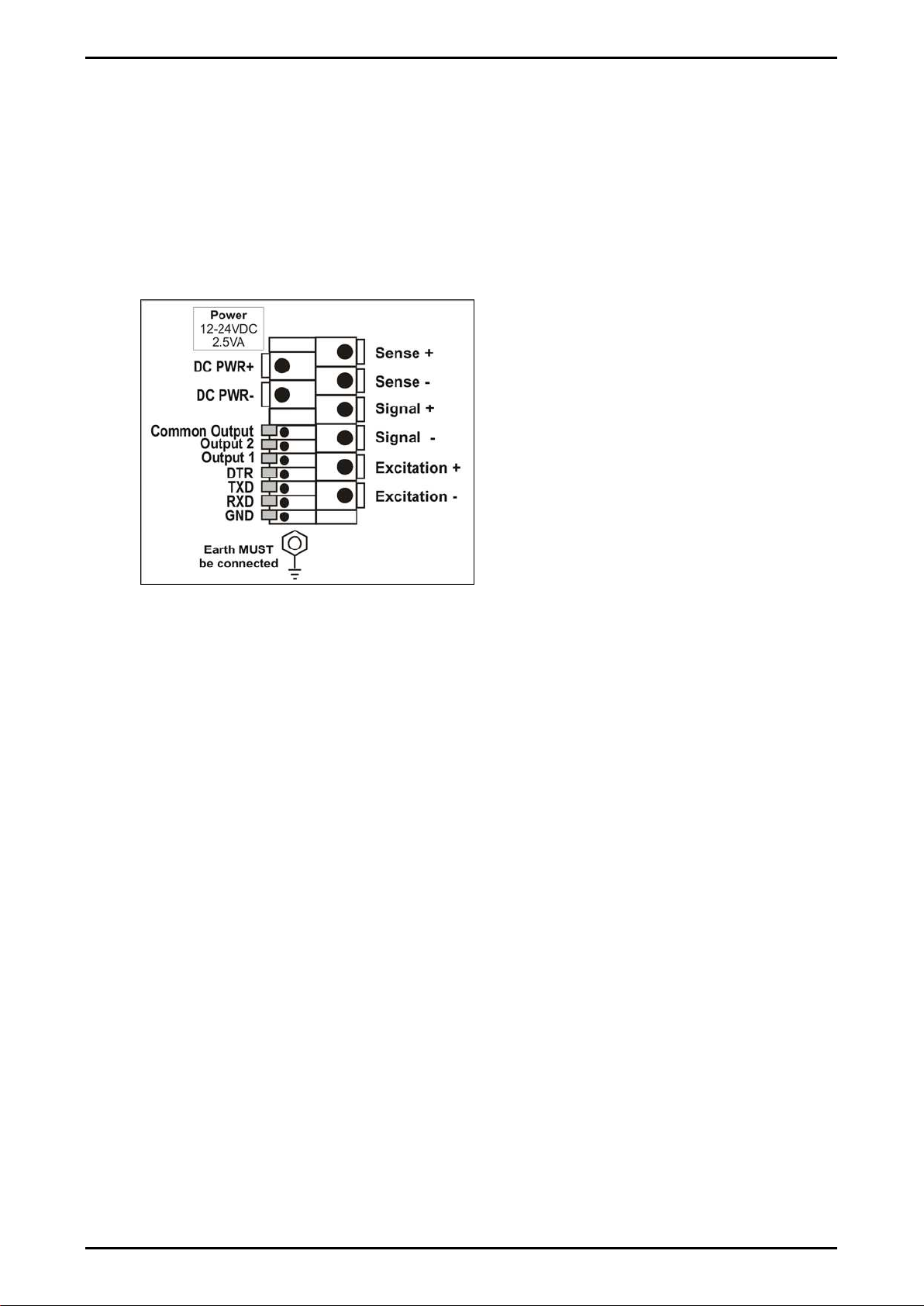
3.6. Cable Connections
All cable connections are made to the rear of the instrument using screwless
terminals. Wires must be stripped of insulation by at least 10mm. To install,
depress the orange lever beside the terminal required and push wire into the hole.
Release the lever and pull gently on the wire to ensure it is securely trapped in the
terminal. It is not necessary to tin the ends of the wire with solder or to add crimp
ferrules to the wires, however, these techniques are also compatible with the
terminals and may ultimately make for a neater job.
Figure 2: Cable Connections
3.7. DC Power (DC PWR + , DC PWR –)
The DC supply need not be regulated, provided that it is free of excessive electrical
noise and sudden transients. The instrument can be operated from a high quality
plug-pack as long as there is sufficient capacity to drive both it and the load cells.
If an optional battery pack is fitted, then the supplied charging system must be used.
3.8. Load Cell Connection
3.8.1. Load Cell Signals and Scale Build
Very low output scale bases may be used but may result in some instability in the
weight readings when used at higher resolutions. Generally speaking, the higher the
load cell output, or the lower the number of divisions, the greater the display stability
and accuracy.
The instrument can display the millivolt-per-volt reading that can be used to check
scale base signal output levels. For more information, refer to SCALE (Scale Base
Test Display) page 40.
The instrument may be connected for either 4-wire or 6–wire operation. To
correspond with the actual cabling installation the instrument must be configured in
setup to the correct setting. For more information, refer to CABLE (4-Wire or 6-
Wire) ⊗page 32.

Reference Manual Rev 3.23 Software Versions 3.xx
Page 9
3.8.2. 4-Wire Connection
The minimum connectivity requirements are the connection of four wires (ie.
Excitation + and – along with Signal + and –). Internally the instrument has a
precision analogue switch that connects the Sense + and – lines directly to the
Excitation + and – lines when 4-wire mode is selected.
A 4-wire connection is only suitable for short cable runs. Where long cable lengths
are needed, a 6-wire extension is required to maintain accuracy.
The BUILD:CABLE option must be set to 4 to allow for 4-wire connection. Refer to
CABLE (4-Wire or 6-Wire) ⊗page 32.
Figure 3: 4-Wire Connections
3.8.3. 6-Wire Connection
The excitation and signal lines are connected the same as for a 4-wire installation.
The extra two wires (Sense + and –) should be connected to the Excitation + and –
lines as close as possible to the load cell itself. Typically these connections are
made in a load cell termination box.
The BUILD:CABLE option must be set to 6 (the default) to allow for 6-wire
connection. Refer to CABLE (4-Wire or 6-Wire) ⊗page 32.
Figure 4: 6-Wire Connections
Reference Manual Rev 3.23 Software Versions 3.xx
Page 10
3.9. Auxiliary Connections
This section provides diagrams to illustrate the terminal connections.
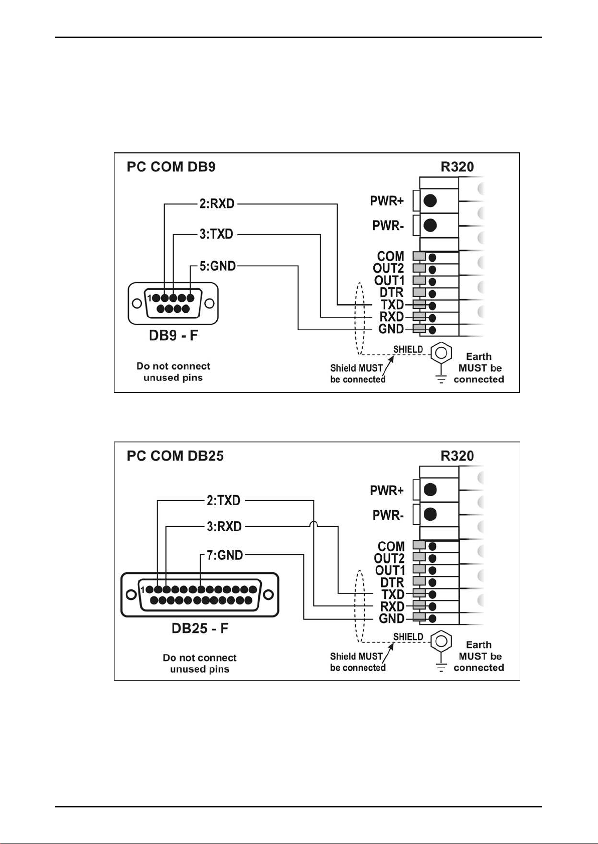
3.9.1. RS-232 Serial
Network: One Instrument to PC (RXD, TXD, GND)
Figure 5: RS-232 – One Instrument to PC using COM Port (DB9)
Figure 6: RS-232 – One Instrument to PC using COM Port (DB25)

Reference Manual Rev 3.23 Software Versions 3.xx
Page 11
Ring Networks: Multiple Instruments to PC (RXD, TXD, GND)
Instruments can be configured in a Ring Network.
The Short Ring Network layout can be used in situations up to a total cable run
length of about 150 m (500 ft) at 9600 baud in a clean EMC environment.If
there are communications errors, or for longer cable runs, lower the baud rate
to 4800 or 2400, and/or use the Long Ring Network in Figure 8 below, which
uses a separate return path from the ‘Last Instrument’ to the PC.
For DB25 connections at the PC connector, refer to Figure 6 above.
When operating in a Ring Network, the Instruments must have:
•same serial port options, i.e., baud, parity, data bits, stop bits;
•unique addresses.
Short Ring Network: Multiple Instruments to PC (RXD, TXD, GND)
Figure 7: RS-232 Short Cable Runs: Ring Network using COM Port (DB9)
Reference Manual Rev 3.23 Software Versions 3.xx
Page 12
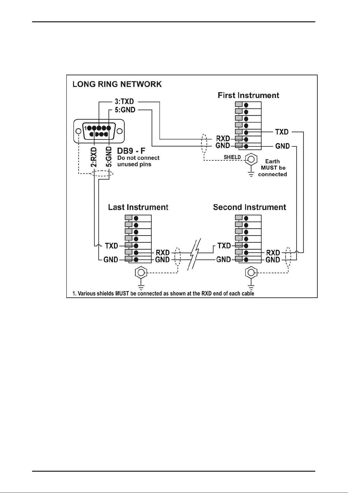
Long Ring Network: Multiple Instruments to PC (RXD, TXD, GND)
The Long Ring Network layout can be used in situations where each leg of the
cable run can be up to about 150 m (500 ft) at 9600 baud. If there are
communications errors, lower the baud rate to 4800 or 2400.
Figure 8: RS-232 Long Cable Runs: Ring Network using COM Port (DB9)
Reference Manual Rev 3.23 Software Versions 3.xx
Page 13
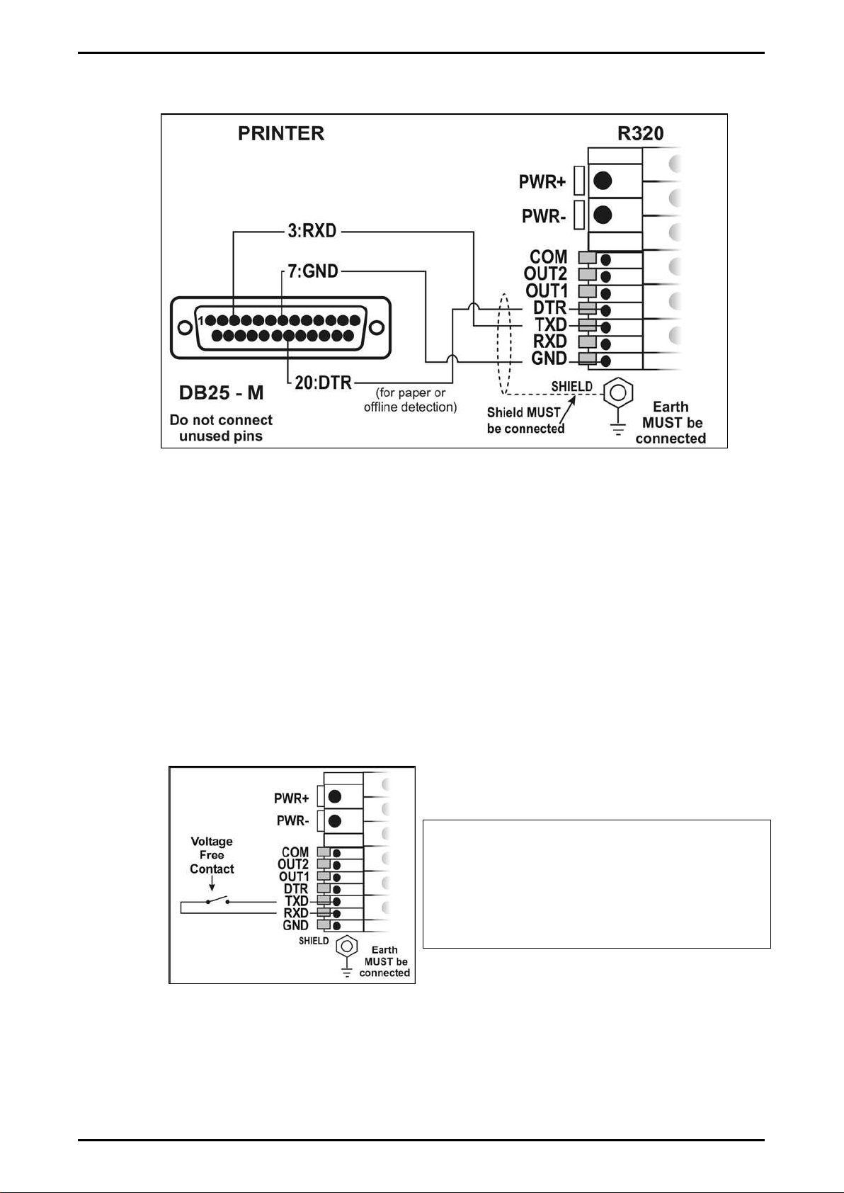
Printer Connections (RXD/TXD, GND and DTR)
Figure 9: RS-232 – Instrument to Printer (DB25)
Remote Display (TXD, GND)
The remote display documentation should be referred to for connection details.
Connect TXD to RXD and GND to GND on the remote display.
3.9.2. Remote Input
The indicator requires a voltage free contact between TXD and RXD to enable
the remote input (ie. SPEC:REM.FN). The SERIAL:TYPE option must be set to
AUTO, PRINT or AUTO.PR. When using SERIAL:TYPE of PRINT or AUTO.PR,
the SPEC:REM.CHR must be set to an appropriate character that will not affect
the printer. This character will be sent repeatedly when the transmitter is idle,
regardless of the state of the DTR line. Note: The remote input will not function
when in setup or when using the opto-LINK.
WARNING
The remote input is a voltage free
contact (eg. button, mechanical relay).
Connection of any active circuitry may
damage the instrument.
Figure 10: Remote Input
Reference Manual Rev 3.23 Software Versions 3.xx
Page 14
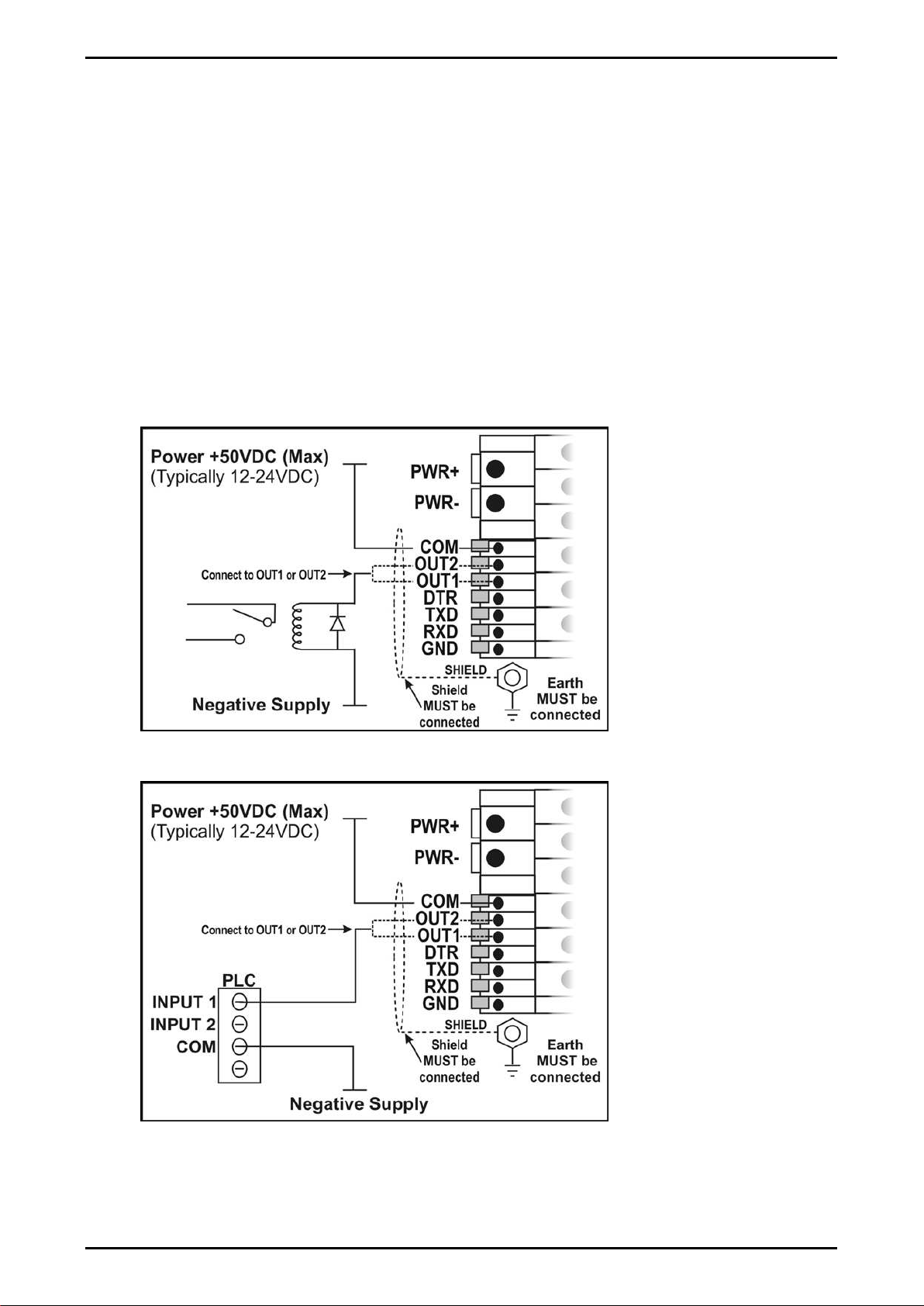
3.9.3. Outputs
The output drivers for the instrument are isolated open emitter transistor drives that
are capable of driving up to a total of 300mA. This configuration allows for the direct
connection of the instrument outputs to most types of PLC.
The voltage applied to the COM terminal appears on the output lines (ie. OUT1 and
OUT2) when the outputs are active (eg. to connect to a PLC connect +24V to the
common terminal). The outputs can then be connected directly to PLC inputs so
when activated are active the PLC will see a 22V signal (approx. - the exact switch
loss will depend on loading of the output).
To drive external loads (eg. relays), connect the relay coil positive supply to the
output common and the output line directly to one side of the relay coil. Connect the
other end of the relay coil to the negative supply. It is recommended that fly-back
diodes or transient suppressors be fitted across relay coils to limit switching noise.
Figure 11: Instrument Outputs to Drive Relay
Figure 12: Instrument Outputs to Drive PLC

Reference Manual Rev 3.23 Software Versions 3.xx
Page 15
3.10.opto-LINK (Optional)
A temporary infrared communications link can be established between the
instrument and a PC using an optional opto-LINK cable. The optional opto-LINK
cable can be used to transfer setup and calibration information from a PC (eg. to be
stored for later use and/or transferred to other instruments). It can also be used to
download software upgrades to the instrument from a PC.
The PC end of the opto-LINK cable is a standard female DB9 connector, or USB
connector. The instrument end of the cable consists of an infrared transceiver,
which attaches to the left side of the instrument display. To facilitate a quick and
simple connection, the infrared transceiver is secured in place by a permanent
magnet located within the head of the opto-LINK.
Refer to opto-LINK Activation page 23 for more information.
WARNING
The opto-LINK head contains a strong magnet and care should be taken with
its proximity to electronic media (eg. credit cards, floppy disks, etc.) and/or
other electronic instrumentation.
Figure 13: opto-LINK Attachment

Reference Manual Rev 3.23 Software Versions 3.xx
Page 16
3.11.Connecting Shields
To obtain full EMC or for RFI immunity, cable shields MUST be connected to the
earth lug on the rear of the instrument.
Figure 14 illustrates an example of possible connections. Also shown are the
connecting cables restrained using cable ties fastened around the cable strain relief
anchors.
Figure 14: Cable Shield Connection
3.11.1. Cable Shield Connection and Earthing
•Care should be taken when connecting shields to maximise EMC or RFI
immunity and minimise earth loops and cross-talk (interference) between
instruments.
•For full EMC or for RFI immunity, termination of the cable shields at the earth lug
is very important. The earth lug of the instrument must be separately connected
to ground potential via a reliable link.
•The instrument should only be connected to earth via a single reliable link to
avoid earth loops.
•Where each instrument is separately earthed, interconnecting cable shields
should be connected at one end only. This also applies to communications
cable shields in Ring Networks, refer to Short Ring Network and Long Ring
Network connections under ‘RS-232 Serial’ pages 11 and 12.
•Caution: Some load cells connect the cable shield directly to the load cell (and
therefore the scale base). Connection of the load cell cable shield in this
situation may be site specific.
3.12.Regulatory Sealing Requirements
To comply with regulatory sealing requirements for each instrument, (ie. to ensure
instruments are not accidentally or deliberately tampered with), it is important that proper
sealing procedures be adhered to. Refer to Sealing page 60 for more information.
Reference Manual Rev 3.23 Software Versions 3.xx
Page 17
4. Data Entry
Throughout the setup and normal weighing mode, different data entry methods are used.
Each method is described below.
When using the keypad for normal operation, press the key on keypad to initiate the
feature.
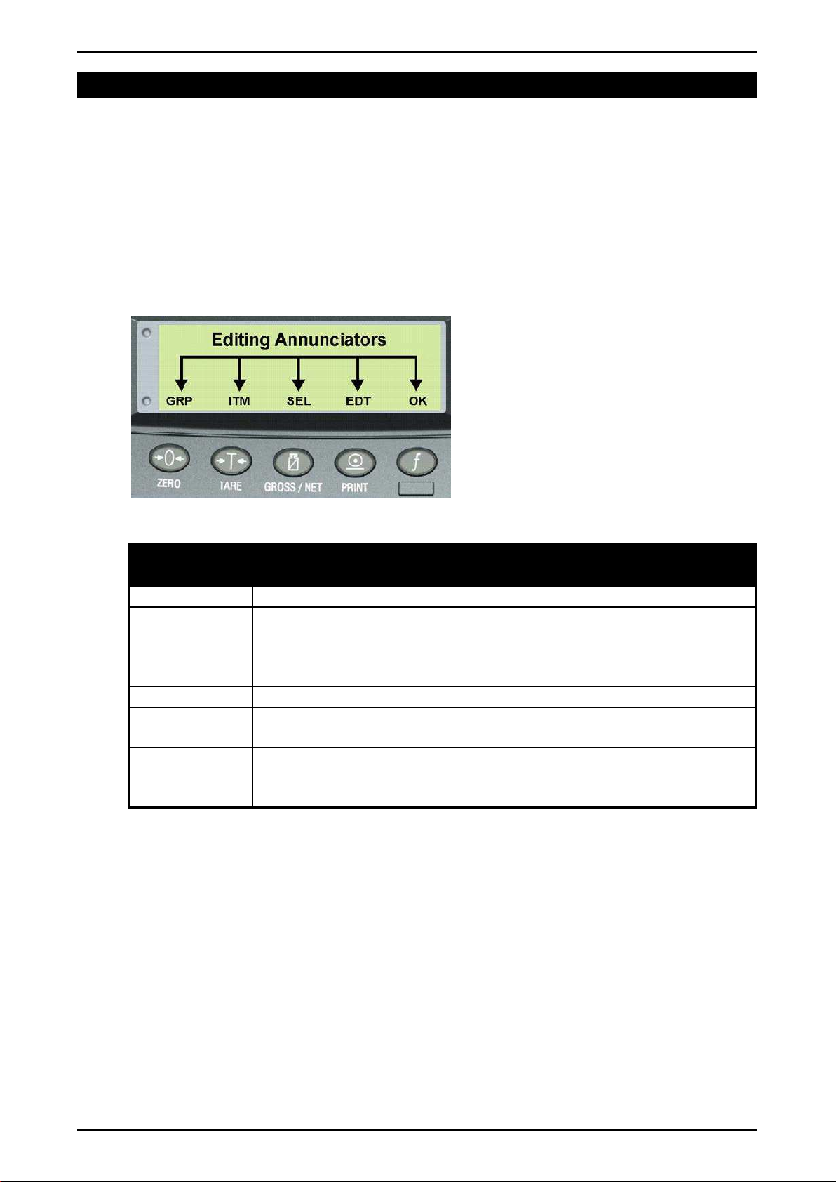
4.1. Editing Annunciators
When in Setup the instrument displays editing annunciators. Figure 15 identifies
each of the editing annunciators. When in Setup, press the corresponding keypad
key below the annunciator.
Figure 15: Editing Annunciators
Editing
Annunciator
Key Name Description
GRP
ZERO
Steps through the list of Groups.
ITM
TARE
Steps through the list of Items.
Press this key to accept changes and return to
the menus.
(Also refer to the OK description below.)
SEL
GROSS/NET
Moves the editing cursor in some editing modes.
EDT
PRINT
Steps through the available options when editing
a particular item.
OK
OK
(FUNCTION)
Press this key to accept changes and return to
the menus.
(Also refer to the ITM description above.)

Reference Manual Rev 3.23 Software Versions 3.xx
Page 18
4.2. Numeric Entry
A numeric entry box allows the input of a number. When entering a number, the
display will show digits with the currently selected digit flashing. The <SEL> key is
pressed to select a digit to change. When the digit is selected the <EDT>key is
pressed to change the digit from 0through 9. The left most digit can also be
changed to a dash (-) to enter a negative number. The <OK> key is pressed to
accept the number that has been entered and return to the menu item.
Upper and lower limits are placed on some entries and an entry outside this range
will cause the instrument to display dashes (ie. - - - - - -).
Example: When in Setup follow the steps below to set Build, Max Capacity.
Press <GRP> repeatedly to display the BUILD group.
Press <ITM> repeatedly to display the CAP item.
Press <SEL> to select CAP and display the current setting (eg. 0000.00kg).
The currently chosen digit will be flashing. Press <SEL> to advance to the next
digit.
When the digit to edit is flashing, press <EDT>repeatedly to cycle from 0through
9.
When the new digit to be set is flashing either press <SEL> to move to the next
digit to edit and repeat the previous step; or press <OK> or <ITM> to accept all
of the displayed digits (including the flashing digit) and re-display the menu item
name.
4.3. Selections and Options
A selection entry requires the choice of a single option from a list. When a Group
and Item have been chosen, the <SEL> key is used to display the current setting for
that item. The <EDT> key can be used to cycle through the options for that item.
When the desired option is displayed the <OK> key can be pressed to accept the
displayed option and re-display the item name.
Example: When in Setup follow the steps below to set Options, Filter.
Press <GRP> repeatedly to display the OPTION group.
Press <ITM> repeatedly to display the FILTER item.
Press <SEL> to select FILTER and display the current setting.
Press <EDT> to cycle through the options for that item.
Press <OK> or <ITM> to accept the displayed option and re-display the menu item
name.

Reference Manual Rev 3.23 Software Versions 3.xx
Page 19
5. Basic Operation
In the most basic configuration, the instrument provides a simple weight readout.
5.1. Display and Controls
Figure 16: Display and Controls Illustration
5.1.1. Front Panel: Visual Display
The front panel has a six-digit LCD display. Figure 16 shows the main elements of
the front panel.
The instrument has various main display sections for the visual output of weight
information. Each display section is described below.
Weight Display
The Weight Display indicates the weight readings, setup information, errors and
warnings.
Units Display
The Units Display shows the units of the weight reading as either grams (g),
kilograms (kg), pounds (lb), tonnes (t) or none. If the instrument is set up for
counting the units display will show pieces (p).
Table of contents
Other Tecsis Measuring Instrument manuals

Tecsis
Tecsis TM1 Series User manual

Tecsis
Tecsis P2590 User manual

Tecsis
Tecsis P2107 User manual

Tecsis
Tecsis P27 Series User manual

Tecsis
Tecsis P3922 User manual

Tecsis
Tecsis E3906 User manual

Tecsis
Tecsis Manoport E3905 User manual

Tecsis
Tecsis E1999X500 User manual

Tecsis
Tecsis E3907 User manual

Tecsis
Tecsis DC400 Series User manual


Popular Measuring Instrument manuals by other brands


Magnetrol
Magnetrol Echotel 962 SIL Safety Manual

Klein Tools
Klein Tools CL800A instruction manual

Endress+Hauser
Endress+Hauser SpectraSensors J22 TDLAS manual

Landis+Gyr
Landis+Gyr 750 Installation, commissioning and maintenance manual

Primes
Primes Cube L1 operating manual

Casella
Casella HB3340-02 Operator's manual


