Tenma 72-7800 User manual

TM
TM
Page <2> V1.025/03/22
Newark.com/exclusive-brands
Farnell.com/exclusive-brands
Element14.com/exclusive-brands
Table of Contents
1. Overview . . . . . . . . . . . . . . . . . . . . . . . . . . . . . . . . . . . . . . . . . . . . . . . . . . . . . . . . . . . 3
2. Open Case and Check. . . . . . . . . . . . . . . . . . . . . . . . . . . . . . . . . . . . . . . . . . . . . . . . . . . . 3
3. Safety Codes. . . . . . . . . . . . . . . . . . . . . . . . . . . . . . . . . . . . . . . . . . . . . . . . . . . . . . . . . 3
4. Electrical Symbols. . . . . . . . . . . . . . . . . . . . . . . . . . . . . . . . . . . . . . . . . . . . . . . . . . . . . . 3
5. External Structure . . . . . . . . . . . . . . . . . . . . . . . . . . . . . . . . . . . . . . . . . . . . . . . . . . . . . . 4
6. LCD Display . . . . . . . . . . . . . . . . . . . . . . . . . . . . . . . . . . . . . . . . . . . . . . . . . . . . . . . . . 4
7. Key Function. . . . . . . . . . . . . . . . . . . . . . . . . . . . . . . . . . . . . . . . . . . . . . . . . . . . . . . . . 5
1. SELECT/CLEAR . . . . . . . . . . . . . . . . . . . . . . . . . . . . . . . . . . . . . . . . . . . . . . . 5
2. RANGE/▲ . . . . . . . . . . . . . . . . . . . . . . . . . . . . . . . . . . . . . . . . . . . . . . . . . . . 5
3. MAX/MIN/STORE . . . . . . . . . . . . . . . . . . . . . . . . . . . . . . . . . . . . . . . . . . . . . . . 5
4. REL/▲ . . . . . . . . . . . . . . . . . . . . . . . . . . . . . . . . . . . . . . . . . . . . . . . . . . . . . 5
5. INRUSH/LOAD . . . . . . . . . . . . . . . . . . . . . . . . . . . . . . . . . . . . . . . . . . . . . . . . 6
6. HOLD/ . . . . . . . . . . . . . . . . . . . . . . . . . . . . . . . . . . . . . . . . . . . . . . . . . . . . 6
8. Measurement Operating Instruction . . . . . . . . . . . . . . . . . . . . . . . . . . . . . . . . . . . . . . . . . . . . 6
1. DC voltage measurement . . . . . . . . . . . . . . . . . . . . . . . . . . . . . . . . . . . . . . . . . . 6
2. AC voltage measurement . . . . . . . . . . . . . . . . . . . . . . . . . . . . . . . . . . . . . . . . . . 6
3. Resistance measurement . . . . . . . . . . . . . . . . . . . . . . . . . . . . . . . . . . . . . . . . . . 7
4. Circuit on-o measurement . . . . . . . . . . . . . . . . . . . . . . . . . . . . . . . . . . . . . . . 8
5. Diode measurement . . . . . . . . . . . . . . . . . . . . . . . . . . . . . . . . . . . . . . . . . . . 8
6. Capacitance measurement . . . . . . . . . . . . . . . . . . . . . . . . . . . . . . . . . . . . . . . . . 9
7. Frequency/duty ratio measurement. . . . . . . . . . . . . . . . . . . . . . . . . . . . . . . . . . . . .10
8. Temperature measurement . . . . . . . . . . . . . . . . . . . . . . . . . . . . . . . . . . . . . . . . .10
9. DC current measurement . . . . . . . . . . . . . . . . . . . . . . . . . . . . . . . . . . . . . . . . . .11
10. AC current measurement . . . . . . . . . . . . . . . . . . . . . . . . . . . . . . . . . . . . . . . . . .11
11. Current signal output function . . . . . . . . . . . . . . . . . . . . . . . . . . . . . . . . . . . . . . .12
12. Power gear (OFF) . . . . . . . . . . . . . . . . . . . . . . . . . . . . . . . . . . . . . . . . . . . . . .12
13. Automatic shutdown function . . . . . . . . . . . . . . . . . . . . . . . . . . . . . . . . . . . . . . .12
9. Technical Specications . . . . . . . . . . . . . . . . . . . . . . . . . . . . . . . . . . . . . . . . . . . . . . . . . .13
1. General specication . . . . . . . . . . . . . . . . . . . . . . . . . . . . . . . . . . . . . . . . . . . .13
2. Environment (For Most Accurate Measurements) . . . . . . . . . . . . . . . . . . . . . . . . . . . . .13
3. Electrical specication. . . . . . . . . . . . . . . . . . . . . . . . . . . . . . . . . . . . . . . . . . . .13
10. Maintenance and Upkeep . . . . . . . . . . . . . . . . . . . . . . . . . . . . . . . . . . . . . . . . . . . . . . . . .16
1. General maintenance . . . . . . . . . . . . . . . . . . . . . . . . . . . . . . . . . . . . . . . . . . . .16
2. Installation or replacement of battery. . . . . . . . . . . . . . . . . . . . . . . . . . . . . . . . . . . .16

TM
TM
Page <3> V1.025/03/22
Newark.com/exclusive-brands
Farnell.com/exclusive-brands
Element14.com/exclusive-brands
1. Overview
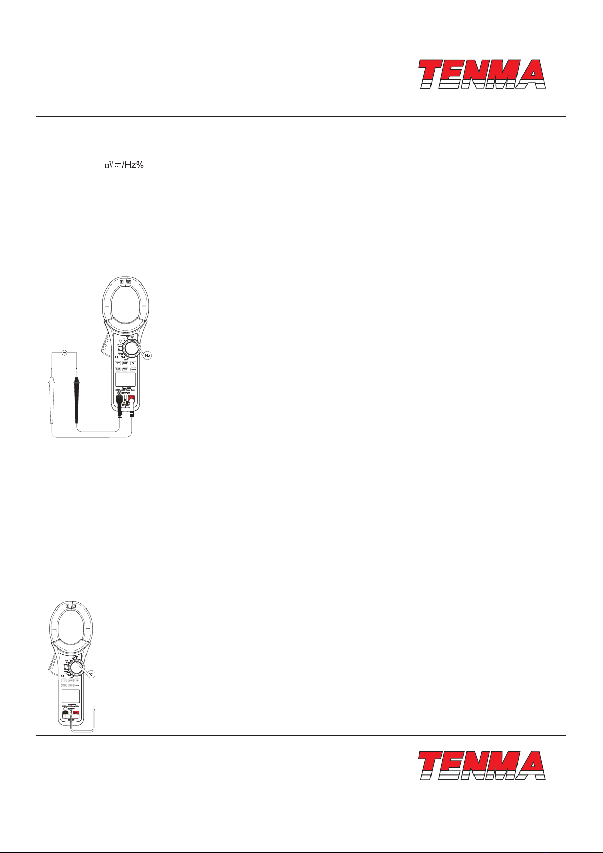
72-7800 is a portable true RMS 5-5/6 bit (6000 Counts), auto range clamp ammeter with analog simulation bar graph. The clamp
ammeter featuring full-function on screen display, full-range overload protection and unique design makes this a highly featured
clamp ammeter with incredible performance. The clamp ammeter is applicable to following measurements: AC/DC voltage, AC/
DC current, surge current, resistance, frequency, maximum/minimum value measurement, relative value measurement, data
recording and read-back, under-voltage display and automatic shutdown function.
The instruction manual includes relevant safety information and warning indication, please read them carefully and strictly
observes all warnings and notes.
2. Open Case and Check
Unpack and remove the instrument. Check the instrument for any damage and verify that the following items are included in
the box. If anything is damaged or missing, please contact your supplier.
• An operating instruction manual
• A test lead
• A Temperature sensor
• A carry case
• A safety certicate
3. Safety Codes
The clamp ammeter is designed and produced strictly in accordance with IEC61010-1 safety standards. It meets the double
insulation over-voltage standardd CAT II 1000V. CAT III 600V and safety standards of pollution degree II. If failure to use the
meter under the relevant operation instruction, the protection provided shall be weakened or lost.
1. Check the clamp ammeter and test leads before use, guard against and damage or abnormal phenomenon. if abnormal
condition is found: bare test leads, damaged classic, no display or random display in LCD, please do not use it. It is forbidden
to use the clamp ammeter without rear cap or rear cap not in place, or otherwise there is risk of electric shock.
2. Damaged test lead should be replaced with a new one.
3. Do not touch the bare wire and connector, used input terminal or the circuit being measured when clamp ammeter is in
operation.
4. Be careful in measuring voltage higher than DC 42V or AC 30V and keep ngers behind the test lead nger guard to prevent
against electrical shock.
5. Set the function range switch at the maximum range position if the scope of measured value could not be dened.
6. Do not use voltage or current values greater than those dened by the clamp meter for safe use.
7. Set function switches to their needed positions before measurement. Before changing functions, remove the test leads from
their measured circuits to prevent damage to the meter.
8. Refrain from storing or using the clamp ammeter in explosive and ammable environment with high temperature, high
humidity and strong electromagnetic eld.
9. Refrain from altering the internal wiring in the clamp ammeter to guard against damage to meter and danger.
10. When LCD display shows the icon “ ”, it is required to replace the battery in time to ensure the measurement accuracy.
11. Power o immediately after measurement. Take out battery when the clamp ammeter is not be in use for a long time.
4. Electrical Symbols
Dual Insulation
Grounding
Warning prompt
AC (Alternating Current)

TM
TM
Page <4> V1.025/03/22
Newark.com/exclusive-brands
Farnell.com/exclusive-brands
Element14.com/exclusive-brands
DC (Direct Current)
Buzzing on-o
Diode
Low battery
AC or DC (Alternating current or direct current)
Danger. High Voltage.
Comply with EU standards
5. External Structure
1. Clamp ammeter body: Designed to safely protect operator from electric shock during proper use.
2. Clamp head pulling handle: Press the trigger to open the clamp head, when release the
trigger, clamp head will partially closed.
3. Functional key: Select basic functions.
4. Analog current output
5. Measure input terminal: Measure the signal input.
6. Toggle: Used to select the measurement of input terminal or analog current output terminal.
7. LCD display area: Displays the measurement data and functional symbols.
8. Dial switch: Select the measurement function position.
9. Clamp head: A device used to measure AC/DC current and convert current into voltage.
6. LCD Display
1. MEM: Memory number
2. MR Read back stored data
3. CLR Stored data clearing
4. Battery under-voltage
5. High voltage warning
6. Display negative reading
7. Auto shutdown
8. Hold mode
9. AC AC measurement

TM
TM
Page <5> V1.025/03/22
Newark.com/exclusive-brands
Farnell.com/exclusive-brands
Element14.com/exclusive-brands
10. DC DC measurement
11. True RMS TrueRMS measurement
12. +System Digit and Simulation Bar Measurement of reading value
13. LPF measurement
14. INRUSH INRUSH current measurement
15. Buzzing on-o measurement
16. Diode measurement
17. Zero AC current gear ZERO
18. Max, Min Maximum and minimum value measurement
19. Relative measurement
20. Manual Manual range
21. Auto Auto Range
22. Measurement unit :
V Voltage unit: Volt
ACurrent unit: Ampere
Ω, kΩ, MΩ Resistance unit: Ω, kΩ, MΩ
nF, µF, mF Capacitance unit: nF, µF, mF
Hz, kHz, MHz Frequency unit: Hz, kHz, MHz
°C, °F Temperature unit: °C,°F
7. Key Function
1. SELECT/CLEAR
Select position by a short press.
With a long press, LCD will display “CLR” symbol, clear stored data record, and then “CLR” symbol disappears, MEM stored
number becomes 0.
2. RANGE/▲
While in data recording mode, enter the manual measurement mode by a short press of the RANGEbutton and change the
manual range. After a long press of the RANGE button, the unit will switch to manual ranging.
While under the data recording recall mode, you can view the stored data upward by pressing this key.
3. MAX/MIN/STORE
With a press on the key, enter MAX/MIN standby mode, LCD will display “----” ; after the second press, LCD will display “MAX”
to enter the maximum value measurement mode, after the third press, LCD will display “MIN” to enter the minimum value
measurement mode. Under non-standby mode, record the current measurement data with a long press on the key.
4. REL/▲
While in the data recording mode (except during DC Current function), enter the relative measurement mode with a short
press. The main display will show the measured value-basic value; the right display will show the basic value. Press again

TM
TM
Page <6> V1.025/03/22
Newark.com/exclusive-brands
Farnell.com/exclusive-brands
Element14.com/exclusive-brands
to exit this mode. While in DC current measurement mode, you can clear the mode with a short press, and display will show
“ZERO”.
While in the data recording mode, you can do a long press to quit the continuous data recording mode. While in the data
recall mode, you can review the data downward by pressing this key.
5. INRUSH/LOAD
At the AC current position, enter INRUSH current measurement mode by pressing the key, after another press , quit the mode.
After long press on the key, enter the read back stored recording data mode, after another press on the key, quit the mode.
6. HOLD/
After a short press, enter the reading hold measurement mode, after another press, quit the mode. After a long press, the
backlight will be illuminated. In case of long press within 10s, backlight will turn o. If no long press, it will be automatically turn
o after 10s.
8. Measurement Operating Instruction
1. DC voltage measurement
1) Insert red test leads in “V” jack and black test leads in “COM” jack.
2) Change the function range switch to the DC voltage measurement position, and connect test leads in parallel with the power
or load to be measured.
3) Directly read the measured voltage value from display.
4) Press SELECT at the DC voltage measurement position to select AC+DC measurement.
Note:
Do not input voltage higher than 1000V. It may be feasible to measure higher voltage, but damage will be caused to the meter.
Beware of potential electric shock when measuring high voltage.
After completing all measurement operations, disconnect test leads from the measured circuit.
When measured voltage is higher than the safety voltage 42V/DC, the meter LC displays high voltage warning symbol “ ” when
inputting overvoltage, higher than DC 1000V position range, the meter will automatically sound intermittent buzzing and high
voltage warning symbol will automatically ash to provide warning symbol.
2. AC voltage measurement
1) Insert red test leads in “V” jack and black test leads in “COM” jack.
2) Push the function range switch to the DC voltage measurement position,and connect test leads in parallel with the power or
load to be measured.
3) Main display will show the true RMS, while the right secondary display shows frequency value. Conditions must be met when
reading frequency value: input range ≥ range × 10%.
4) Press SELECT at the AC voltage measurement position to select LPF measurement .

TM
TM
Page <7> V1.025/03/22
Newark.com/exclusive-brands
Farnell.com/exclusive-brands
Element14.com/exclusive-brands
Note:
Beware of potential electric shock when measuring high voltage.
After completing all measurement operations, disconnect test leads from the measured circuit.
When the measured voltage is greater than the 30V AC, the meter LCD displays a high voltage warning symbol “ ” If the
measured voltage is greater than the 1000V limit, the meter will intermittently buzz while the high voltage warning “ ” ashes.
AC conversion adopts the AC coupling true RMS response mode, sine wave input for correction.
The accuracy of non-sine wave should be adjusted as follows:
Crest factor 1.4~2.0, accuracy should be increased 1%;
Crest factor 2~2.5, accuracy should be increased 2.5%;
Crest factor 2.5~3, accuracy should be increased 4%;
3. Resistance measurement
1) Insert red test leads in “Ω’’jack and black test leads in “COM” jack.
2) Turn the function range switch to the measurement position “ ” press SELECT to select resistance measurement Ω and
connect test leads in parallel with the two terminals of measured resistance .
3) Directly read the measured resistance value from display.
Note:
If the resistance open circuit or resistance being measured exceeds the maximum range of the meter, display will show “OL” .
Before measuring line resistance, the circuits should be powered o and all capacitors properly discharged to insure measure-
ment accuracy.
When measuring low resistance, a measurement error of 0.1Ω ~ 0.2Ω will be caused by the test leads. To acquire an accurate
reading, short the test leads and press the Relative Measurement (TRIANGLE SYMBOL). This value will then be deducted from
the resistance measurement.
If the resistance value Is not less than 0.5 0 when test leads are short circuit, please inspect test leads.
In measuring resistance over 1MΩ, it might take several seconds to stabilize the reading. This is normal for high resistance
measurement. To acquire stable reading, the short test lead can be used for measurement.
Do not input voltage higher than DC 42V or AC 30V, which may cause personal injury.
After completing all measurement operations, disconnect the test leads from the circuit being measured.

TM
TM
Page <8> V1.025/03/22
Newark.com/exclusive-brands
Farnell.com/exclusive-brands
Element14.com/exclusive-brands
4. Circuit on-o measurement
1) Insert red test leads in “Ω” jack and black test leads in “COM” jack.
2) Push the function range switch to the measurement Position “Ω ”, press SELECT to select circuit on-o measurement
and connect test leads in parallel with the two terminals of measured circuit. When the measured resistance between two
terminals <30Ω, the circuit should be deemed conductive, buzzer will sound continuously. When resistance is ≥30Ω, the
buzzer will not sound.
3) Directly read the measured resistance value loaded by the circuit from display.
Note:
When checking a circuit, prior to measurement, be certain to power o all power sources and discharge any inline capacitors.
With respect to the circuit on-o measurement, open-circuit voltage is approximately -3.5V and range should be 600Ω
measurement Position
Do not input voltage higher than DC 42 V or AC 30V, which may cause personal injury.
After completing all measurement operations, disconnect the test leads from the measured circuit.
5. Diode measurement
1) Insert red test lead in “ ” jack and black test lead in “COM” jack. Polarity of red and black test leads are respectively “+”
and “-”.
2) Select the “Ω ” position on the function switch, and press SELECT to select diode measurement and to display the
forward diode voltage drop. For silicon diode junctions, the general voltage drop value is between 500~800mV as a normal
value.

TM
TM
Page <9> V1.025/03/22
Newark.com/exclusive-brands
Farnell.com/exclusive-brands
Element14.com/exclusive-brands
Note:
“OL” will be displayed when the measured diode is open-circuit or polarity is inversely connected.
Before diode measurement, make sure all circuits are powered o and discharge any capacitors for best measurement ac-
curacy.
The test open-circuit voltage of diode is approximately 3.5V.
Do not input voltage higher than DC 42V or AC 30V, which may cause personal injury.
After completing all measurement operations, disconnect the test leads from the measured circuit.
6. Capacitance measurement
1) Insert red test lead in “ ” jack and black test lead in “COM” jack.
2) Select the “ ” position on the function switch, and connect the test lead in parallel with the capacitor or circuit to be measured.
3) Directly read out the capacitance value of measured circuit from display. It is recommended to carry out capacitance
measurement with the short test leads, thus reducing the impact caused by distributed capacitance.
Note:
If the measured capacitance is short circuited or capacitance exceeds the maximum range of the meter, display will show “OL”.
While in the Capacitance Measurement mode, the simulated analog measurement bar is disabled. It will take a longer amount
of time to obtain measurements if the capacitance is greater than 600µF.
For best measurement accuracy, discharge capacitors before the test, and then connect leads for measurement. Some high
voltage capacitors can cause damage
After completing measurement operation, disconnect the test leads from the measured capacitance.

TM
TM
Page <10> V1.025/03/22
Newark.com/exclusive-brands
Farnell.com/exclusive-brands
Element14.com/exclusive-brands
7. Frequency/duty ratio measurement
1) Insert red test leads in “Hz” jack and black test leads in“COM” jack.
2) Select the “ ” position on the function switch, and press the red key to select the “Hz” frequency measurement
function. Connect the rest leads in parallel with signal to be measured.
3) Directly read out the measured frequency value from display.
4) Press SELECT to select duty ratio measurement.
Note
For measuring signal with frequency between 10Hz ~ 40kHz
The amplitude must be between 1Vrms and 30Vrms. Upper frequency limit 40MHz
Do not input frequency higher than 30V rms, which may cause personal injury
After completing all measurement operations, disconnect the test leads from the measured circuit
8. Temperature measurement
1) Select the “°C/°F” position on the function switch. The display will initially read “OL”. Short the standard test leads to display
room temperature.
2) Insert temperature K type socket in the corresponding hole as per the diagram.
3) Put temperature probe directly on the measured surface, several seconds later, directly read out the measured Celsius
temperature value from LCD.
4) Press SELECT to select Fahrenheit temperature measurement.
Note
The meter should be operated when ambient temperature is outside 18°C ~ 28°C range for accurate measurement, particularly
evident in low temperature environment.
Do not input voltage higher than DC 42V or AC 30V, which may cause personal injury.
After completing temperature measurements, remove the temperature probe.

TM
TM
Page <11> V1.025/03/22
Newark.com/exclusive-brands
Farnell.com/exclusive-brands
Element14.com/exclusive-brands
9. DC current measurement
1) Select the “ ” on the function switch. If the display does not read zero, press REL to reset the voltage measurement to zero.
You may need to repeat this after each current measurement.
2) Squeeze clamp trigger to open the clamp head and place around single conductor to be measured. Slowly release the clamp
trigger to make certain that the head is completely closed. Keep the conductor centred in the clamp head. Please note that
only one conductor can be measured at a time; multiple conductors will product an incorrect measurement.
3) Directly read out the measured DC current value from display.
4) Press SELECT at the DC current position to select AC+DC measurement.
Note:
Current measurement must be taken between 0° and 40°C. If a positive reading is achieved after measure DC current, the
current direction run from the base of the meter to the front of the meter. Never release the clamp too abruptly as the component
is sensitive to shock, heat, and magnet elds. Impact of the clamp jaws will also cause short term reading variation.
Be sure the conductor to be measured is clamped at the center of clamp head, If not, an additional reading error of ±1% may
be resulted.
10. AC current measurement
1) Select the “A~” on the function switch. Squeeze clamp trigger to open the clamp head and place around single conductor
to be measured. Slowly release the clamp trigger to make certain that the head is completely closed. Keep the conductor
centred in the clamp head. Please note that only one conductor can be measured at a time; multiple conductors will product
an incorrect measurement.
2) Main display will show the true RMS, while the right secondary display shows frequency value. Conditions must be met
when reading frequency value: input range ≥ range × 10%.
3) Press SELECT at the AC voltage measurement position to select LPF measurement
4) When measuring an initial surge current, press INRUSH while in the AC Current function. The meter will display “—” while
in the standby INRUSH mode. After starting the electrical appliance being measured, the instant-on current of the appli-
ance will be displayed. Press INRUSH again to exit the surge current measurement.
Note:
Current measurement must be taken between 0° and 40°C. If a positive reading is achieved after measure DC current, the
current direction will from the base of the meter to the front of the meter. Never release the clamp too abruptly as the compo-
nent is sensitive to shock, heat, and magnet elds. Impact of the clamp jaws will also cause short term reading variation.
Be sure the conductor to be measured is clamped at the centre of clamp head, if not, an additional reading error of +1% may
be resulted
AC Conversion utilizes the AC True RMS response and sine wave measurement for correction. The accuracy of non-wine
wave measurements can be adjusted as follows:
Crest factor 1.4~2.0, accuracy should be increased 1%;

TM
TM
Page <12> V1.025/03/22
Newark.com/exclusive-brands
Farnell.com/exclusive-brands
Element14.com/exclusive-brands
Crest factor 2.0~2.5, accuracy should be increased 2.5%;
Crest factor 2.5~3.0, accuracy should be increased 4.0%;
11. Current signal output function
The 72-7800 clamp meter features a current output signal function. The signal converts measured current into voltage at a
ratio of 1A/amV readable by other meters and pieces of test equipment. For example, this allows you to observe current as a
waveform on an oscilloscope, or collect data with PC enabled equipment.
Note:
Do not input voltage greater than 5V, as this could damage the meter.
12. Power gear (OFF)
Instrument will be powered o.
13. Automatic shutdown function
If buttons are not pressed or if function rotary knob is not used within given time (15 minute default), the display will turn o,
and the instrument enters a low-power mode. The meter can be awaken by pressing a button or turning the knob.
Note:
Current measurement must be taken between 0° and 40°C. If a positive reading is achieved after measure DC current, the
current direction will from the base of the meter to the front of the meter. Never release the clamp too abruptly as the component
is sensitive to shock, heat, and magnet elds. Impact of the clamp jaws will also cause short term reading variation.
Be sure the conductor to be measured is clamped at the center of clamp head. If not, an additional reading error of ±1% may
be resulted

TM
TM
Page <13> V1.025/03/22
Newark.com/exclusive-brands
Farnell.com/exclusive-brands
Element14.com/exclusive-brands
9. Technical Specications
1. General specication
• Liquid crystal display: 3-5/6 digit LCD, maximum display 6000 count.
• Polarity display: auto positive and negative polarity display.
• Overload display: “OL” or “-OL” .
• Low voltage display: “ ” indicates that battery voltage is lower than working voltage.
• Therefore, the battery needs to be replaced.
• Sampling rate: 3 per second
• Type of sensor: Hall eect sensor for DC/AC measurement
• Test position error: an additional reading error of ±1% may be resulted when the power to
• be measured is not clamped at the center of clamp head
• Resistance to impact strength: 1m fall impact
• Maximum clamp opening: diameter 63mm
• Maximum size of current lead: diameter 60mm
• Electromagnetic eld impact: the application of device near electromagnetic eld may result in
• unstable display or inaccurate reading.
• Power requirement: 6LF22 9V alkaline battery
• Dimensions: 11.7″ × 4.2″ × 1.9″ (298mm × 107mm × 47mm)
• Weight: 26oz (726g) - inclusive of battery.
2. Environment (For Most Accurate Measurements)
Indoor
• Maximum elevation: 6560’ (2000m)
• Safety Standard: CAT IV 600, CAT III 1000; Pollution grade 2
• Operating humidity and temperature:
O°C ~ 30°C(≤80%RH), 30°C~40°C (not greater than 75%RH),
40°C~50°C(not greater than 45%RH)
• Storage humidity and temperature: -20°C~+60°C (not greater than 80%RH)
3. Electrical specication
• Accuracy: ±(%+ count ), one-year calibration time
• Ambient temperature: 23°C ±5°C
• Ambient humidity: ≤80% RH
• Temperature coecient: 0.1 × (accuracy) /°C
(1) DC voltage
Range Resolution Accuracy: ±(% reading + count)
6V 0.001V
±(0.5%+2)60V 0.01V
600V 0.1V
1000V 1V ±(1%+2)
Input impedance: about 10MΩ
Overload protection: 1000V
(2) AC voltage V~
Range Resolution Accuracy: ±(% reading + count)
6V 0.001V 40Hz~400Hz 400Hz~1kHz
60V 0.01V ±(1%+3) ±(2%+3)
600V 0.1V

TM
TM
Page <14> V1.025/03/22
Newark.com/exclusive-brands
Farnell.com/exclusive-brands
Element14.com/exclusive-brands
Range Resolution Accuracy: ±(% reading + count)
1000V 1V ±(1.2%+3) ±(2.5%+3)
Input impedance: about 10MΩ
Overload protection: 1000V
Display: true RMS, applicable to 10%-100% of the range.
(3) Voltage AC+DC
Range Resolution Accuracy: ±(% reading +count)
6V 0.001V 40Hz~400Hz 400Hz~1kHz
60V 0.01V ±(2%+20) ±(4%+20)
600V 0.1V
1000V 1V ±(2.5%+20) ±(5%+20 )
Input impedance: about 10MΩ
Overload protection: 1000V
Display: true RMS, applicable to 10%~100% of the range.
(4) DC current A
Range Resolution Accuracy: ± (% reading + count)
600A 0.1A ±(1.5%+5)
2500A 1A ±(2.5%+5)
(5) AC current
Range Resolution Accuracy: ± (% reading + count)
600A 0.1A ±(1.5%+5)
2500A 1A ±(2.5%+5)
Display: true RMS, applicable to 10%-100% of the range.
Frequency response: 50Hz~60Hz
The clamp will vibrate slighly when measuring 2000 AC current with no impact on measuring accuracy.
(6) Current: AC+DC
Range Resolution Accuracy: + (% reading + count)
600A 0.1A ± (3. 0%+20)
2500A 1A ± (5. 0%+20)
Display: true RMS, applicable to 10%~100% of the range.
Frequency response: 50Hz~60Hz
It is normal that the clamp vibrates slightly when measuring 2000 AC current, no impact on measuring accuracy.
(7) Resistance Ω
Range Resolution Accuracy: ± (% reading + count)
600Ω 0.1 Q Under REL state: ±(1.2%+2)
6kΩ 0.001kΩ
±(1%+2)60kΩ 0.01kΩ
600kΩ 0.1kΩ
6MΩ 0.001MΩ ±(1.2%+2)
60MΩ 0.01MΩ ±(1.5%+2)
Overload protection: 1000V

TM
TM
Page <15> V1.025/03/22
Newark.com/exclusive-brands
Farnell.com/exclusive-brands
Element14.com/exclusive-brands
(8) Continuity test
Range Resolution Remark
0.1Ω
Open-circuit voltage is about -3.5V; Sound continuity is
set as <30Ω, buzzer continuously sounds.
Short circuit is set as ≥30Ω, buzzer will not sound.
Overload protection: 1000V
(9) Diode
Range Resolution Remark
0.001V
Open circuit voltage is about 3.5V, able to measure the PN junction
<3V forward voltage drop value.
The normal voltage value of silicon PN junction is about 0.5~0.8V.
Overload protection: 1000V
(10) Capacitance
Range Resolution Accuracy: ± (% reading + count)
60nF 0.01nF Under REL state: ±(3%+5)
600nF 0.1nF
±(3%+5)6µF 0.001µF
60µF 0.01µF
600µF 0.1µF ±(4%+5)
6000µF 1µF ±(5%+5)
60mF 0.01mF Reference value
Overload protection: 1000V
(11) Frequency Hz
Range Resolution Accuracy: + (% reading + count)
60Hz 0.001Hz
±(0.1 %+3)
600Hz 0.01Hz
6kHz 0.0001kHz
60kHz 0.001kHz
600kHz 0.01kHz
6MHz 0.0001MHz
60MHz 0.001MHz
Overload protection: 1000V
Input range a: 10Hz~40MHz: 1Vrms ≤a ≤S30Vrms;
When >40MHz: unspecied.
(12) Duty ratio %
Range Resolution Error limit: ± (% reading + count)
10% ~ 90 %(10Hz ~ 2kHz) 0.01 ±(1.2%+30)
Overload protection: 1000V
(13) Temperature
Range Resolution Error limit: ± (% reading + count)
-40°C~40°C 1°C ±(2%+10)

TM
TM
Page <16> V1.025/03/22
Newark.com/exclusive-brands
Farnell.com/exclusive-brands
Element14.com/exclusive-brands
Range Resolution Error limit: ± (% reading + count)
40°C~400°C 1°C ±(1%+10)
40°C~1000°C ±2.5%
-40°F~104°F
2°F
±(2%+18)
104°F~752°F ±(1%+18)
752°F~1832°F ±2.5%
Overload protection: 1000V
Temperature sensor: K type (Ni-Cr and Ni- Si) thermocouple
(14) AC voltage + LPF
Range Resolution Remark
6V 0.001V
Intercept AC voltage signal higher than 1kHz
60V 0.01V
600V 0.1V
1000V 1V
(15) AC Current+ LPF
Range Resolution Remark
600A 0.1A Intercept AC voltage signal higher than 1kHz
2500A 1A
10. Maintenance and Upkeep
1. General maintenance
Warning: to prevent electrical shock, keep the test leads disconnected if opening the housing for battery or fuse maintenance.
a. The clamp meter should be serviced or repaired only by a qualied professional technician.
b. When needed, wipe the outer casing with a clean cloth.
Do not use abrasive materials or solvents.
2. Installation or replacement of battery
A 9V (6LF22) battery provides power for the clamp meter. To install or replace battery:
a. Turn o the clamp meter, and remove test leads from input terminals.
b. Gently place the meter panel face down, and remove battery cover screw. Lift the battery cover o, and install new battery
-paying attention to the indicated polarity.
c. Only use the same type of 9V Alkaline battery. Do no try to t with another battery type or mains power.
d. After installing battery, replace and secure battery cover and screw.
Important Notice : This data sheet and its contents (the “Information”) belong to the members of the AVNET group of companies (the “Group”) or are licensed to it. No licence is granted for
the use of it other than for information purposes in connection with the products to which it relates. No licence of any intellectual property rights is granted. The Information is subject to change
without notice and replaces all data sheets previously supplied. The Information supplied is believed to be accurate but the Group assumes no responsibility for its accuracy or completeness,
any error in or omission from it or for any use made of it. Users of this data sheet should check for themselves the Information and the suitability of the products for their purpose and not make
any assumptions based on information included or omitted. Liability for loss or damage resulting from any reliance on the Information or use of it (including liability resulting from negligence or
where the Group was aware of the possibility of such loss or damage arising) is excluded. This will not operate to limit or restrict the Group’s liability for death or personal injury resulting from its
negligence. TENMA is the registered trademark of Premier Farnell Limited 2019.
Table of contents
Other Tenma Measuring Instrument manuals

Tenma
Tenma 72-3545 User manual

Tenma
Tenma 72-14415 User manual

Tenma
Tenma 72-7222 User manual

Tenma
Tenma 72-14400 User manual

Tenma
Tenma 72-7712 User manual

Tenma
Tenma 72-1025 User manual

Tenma
Tenma 72-9490 User manual

Tenma
Tenma 72-9395 User manual

Tenma
Tenma TEN01073 User manual

Tenma
Tenma Smart Tweezer ST-5S-BT2 User manual
Popular Measuring Instrument manuals by other brands

PCB Piezotronics
PCB Piezotronics IMI SENSORS 625B10 Installation and operating manual

Endress+Hauser
Endress+Hauser PROFIBUS PA Levelflex FMP56 operating instructions

berlinger
berlinger Fridge-tag 3 QUICK INFO, SET UP

scigiene
scigiene AW1 user manual

Heathkit
Heathkit SG-6 Assembling and using

PEWA
PEWA AMPROBE IR610A operating instructions