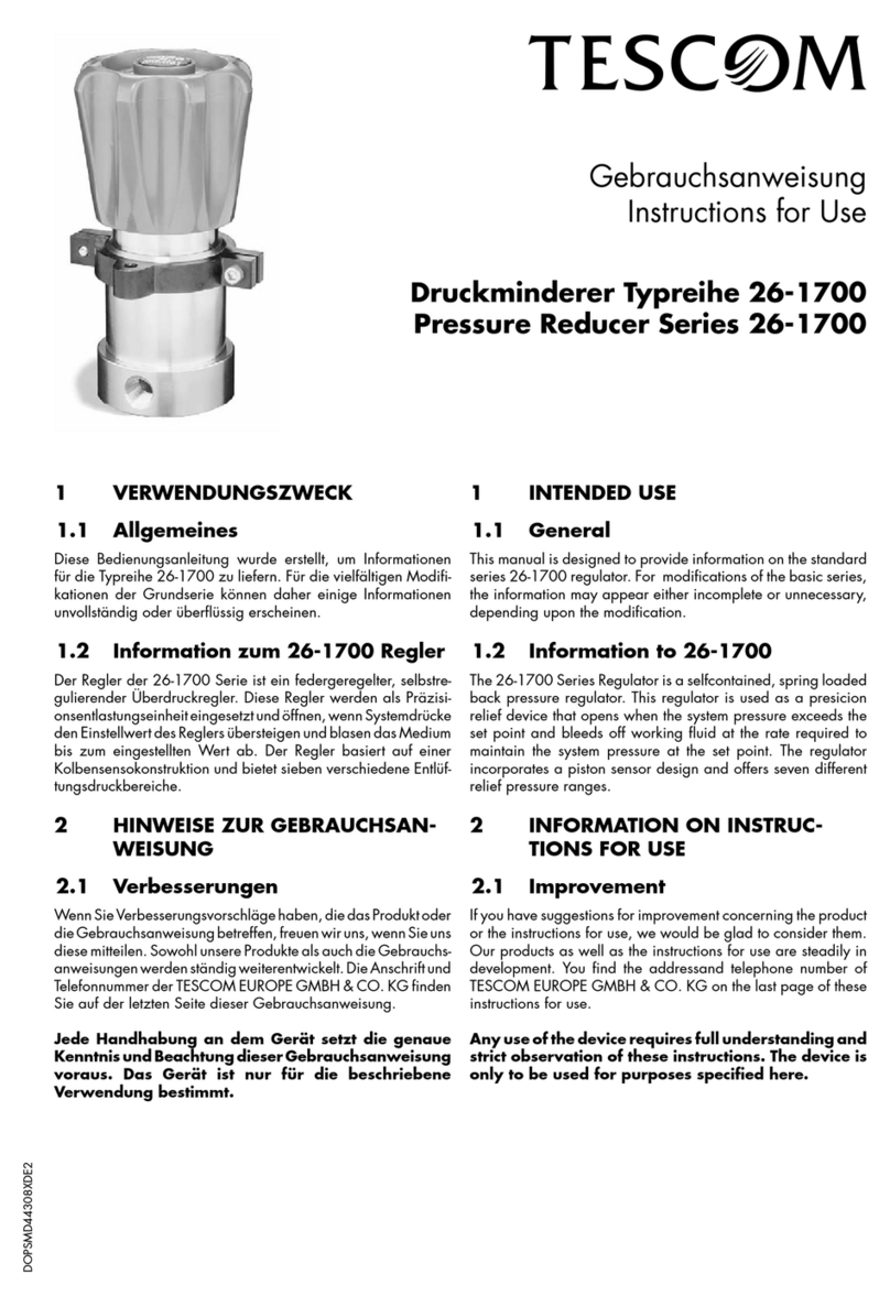
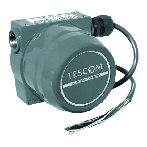
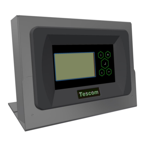
Tescom ER3000 User manual

ER3000 Electronic
Pressure Controller
User Manual

PRODUCT WARRANTY
Tescom ("Tescom") warrants to the party who purchases products for initial use
directly from Tescom, its affiliates or authorized distributors or representatives
("Initial Purchaser") that products manufactured and sold by its Industrial Controls
Group (“IC”) are free from defects in materials and workmanship under normal use
and service for a period of 365 days from the date of delivery of the products
("Warranty Period"). This warranty applies only to the Initial Purchaser. This
warrantyis not transferable to subsequent purchasers or users of the products.
During the Warranty Period, Tescom will, in its sole discretion, repair or replace, free
of charge at its factory in Minnesota, any product or part thereof that is found by
Tescom, after reasonable notification by the Initial Purchaser, to have been defective
in materials or workmanship. The Initial Purchaser must pay all shipping costs for
warranty service and is responsible for risk of loss or damage of products during
shipment. Tescom does not warrant, and will not pay for, any repairs or replacement
made during the Warranty Period by anyone other than personnel authorized by
Tescom or its IC Group to make such repairs or replacement.
THE ABOVE WARRANTY IS IN LIEU OF ALL OTHER WARRANTIES.
TESCOM AND ITS IC GROUP MAKE NO OTHER EXPRESS OR IMPLIED
WARRANTY, AND IN PARTICULAR AND WITHOUT LIMITATION MAKE
NO IMPLIED WARRANTIES OF MERCHANTABILITY OR FITNESS FOR
PARTICULAR PURPOSE. The Initial Purchaser's only remedy under this warranty
is repair or replacement of the products during the Warranty Period. This warranty
does not apply to any product which has been damaged by accident, abuse, misuse,
modification or lack of proper maintenance. NEITHER TESCOM, NOR ITS IC
GROUP WILL BE LIABLE FOR ANY CONSEQUENTIAL, SPECIAL,
INCIDENTAL OR INDIRECT DAMAGES, INCLUDING WITHOUT
LIMITATION, LOST PROFITS.
INDUSTRIAL CONTROLS
12616 Industrial Boulevard
Elk River, Minnesota 55330-2491
1-800-447-1250 (763) 241-3238
FAX (763) 241-3224
e-mail: na.tescom@emerson.com
www.tescom.com
Windows3.1, Windows95, WindowsNT, DOS, and Visual Basicare trademarks of Microsoft
Corporation. LabVIEWand LabWindows/CVI are trademarks of National Instruments

Installation & Operation Precautions
TESCOM Industrial Controls
INTRODUCTION
Prior to installing or operating any equipment, read and follow all the information listed. Improper
application and operation can result in damage to equipment or severe personal injury.
All possible hazards and precautionary measures cannot be covered here. It is recommended that
prior to using this equipment, you fully understand and comply with existing safety regulations.
OXYGEN SERVICE
Specification of the materials in regulators used for oxygen service is the USER’S
RESPONSIBILITY. Cleaning for oxygen service to 3000 PSIG is supplied standard by Tescom at
no additional cost for mechanical regulators. Cleaning for service above 3000 PSIG may be
contracted through an outside source.
COMPATIBILITY
Tescom may suggest material for use with specific media upon request. Suggestions are based on
technical compatibility resources through associations and manufacturers. Tescom does NOT
guarantee materials to be compatible with specific media - THIS IS THE RESPONSIBILITY OF
THE USER! Users must test under operating conditions to determine suitability of materials in an
application.
PRESSURE RATING
Verify the designed pressure rating of the equipment. Check supply lines, fittings, connections,
filters, valves and gauges. All must be adequate for the supply and operating pressure.
RELIEF PROTECTION
A regulator is not intended to be used as a shut-off device. A pressure relief device should be
installed downstream of the regulator to protect the process equipment in the case of a rise in
operating pressure. When the regulator is not in use, the supply pressure should be closed.
FILTRATION
An auxiliary upstream filter is recommended for use in all media. Gaseous media should be free of
excessive moisture to prevent icing of the equipment.
MAINTENANCE
Periodic inspection and scheduled maintenance of your equipment is essential for continued safe
and satisfactory operation. The frequency of servicing will depend on the application.
REPAIR SERVICE
Any equipment in need of service should be returned to your equipment supplier for evaluation and
prompt service. If repairable, your equipment will be restored to the original factory performance
specifications. A flat fee repair charge has been established for each standard model and the
original equipment warranty will be reinstated after a complete overhaul.
ASSEMBLY/INSTALLATION DRAWINGS & BILLS OF MATERIAL
Drawings and parts lists for your product may be obtained by calling 1(800) 447-1204.
Tescom will provide these by fax or mail. Your local distributor can provide additional
assistance.

TABLE OF CONTENTS
1. INTRODUCTION ----------------------------------------------------------------7
2. SPECIFICATIONS---------------------------------------------------------------8
2.1 ENCLOSURE----------------------------------------------------------------------8
2.2 MEDIA----------------------------------------------------------------------------8
2.3 INLET PRESSURE ----------------------------------------------------------------8
2.4 ENVIRONMENT-------------------------------------------------------------------8
2.5 FLOW RATE ----------------------------------------------------------------------8
2.6 POWER REQUIREMENT----------------------------------------------------------8
2.7 RS485 COMMUNICATION INTERFACE -----------------------------------------8
2.8 ACCURACY -----------------------------------------------------------------------9
2.9 RESPONSE TIME -----------------------------------------------------------------9
2.10 PORTS ----------------------------------------------------------------------------9
2.11 WEIGHT --------------------------------------------------------------------------9
2.12 EXTERNAL ANALOG INPUT IMPEDANCE ---------------------------------------9
2.13 DIGITAL OUTPUTS---------------------------------------------------------------9
2.14 DIGITAL INPUTS -----------------------------------------------------------------9
2.15 ANALOG OUTPUT----------------------------------------------------------------9
2.16 SENSOR UPDATE RATE----------------------------------------------------------9
3. ER3000 PART NUMBERING SYSTEM------------------------------------ 10
4. INSTALLATION---------------------------------------------------------------- 11
4.1 INTERFACE CABLE ASSEMBLIES---------------------------------------------- 11
4.2 VOLTAGE/CURRENT SELECT JUMPERS -------------------------------------- 12
4.3 BASIC ER3000 TO PC WIRING----------------------------------------------- 13
4.4 SETTING UP A TYPICAL ER3000 PRESSURE CONTROL SYSTEM------------ 14
4.4.1 Plumb the External Regulator and Transducer ---------------------- 14
4.4.2 Mount the ER3000 ------------------------------------------------------- 15
4.4.3 Connect the Power Supply ---------------------------------------------- 15
4.4.4 Connect RS485 Interface Connections -------------------------------- 15
4.4.5 Install the “ER3000 (CVI)” Windows Program---------------------- 15
4.4.6 Communicate tothe ER3000, usingtheER3000(CVI)WindowsProgram 15
4.4.7 Connect Transducer Wiring--------------------------------------------- 16
4.4.8 Connect Pressure to the System ---------------------------------------- 16
4.4.9 Tune the System----------------------------------------------------------- 16
4.5 ADDITIONS AND VARIATIONS TO THE TYPICAL SYSTEM--------------------- 17
4.5.1 Transducer Wiring Configurations------------------------------------- 17
4.5.2 Analog Setpoint Source-------------------------------------------------- 19
4.5.3 Monitor the Feedback Signal ------------------------------------------- 21
4.5.4 Profile Control / Digital Inputs----------------------------------------- 23
4.5.5 Switch Feedback Control to a Second Feedback Source------------ 24

4.5.6 Monitor Analog Signals ------------------------------------------------- 24
4.5.7 Networking ER3000’s---------------------------------------------------- 25
4.5.8 Digital Outputs ----------------------------------------------------------- 26
4.5.9 Monitor Internal Sensor using the Analog Output------------------- 27
5. OPERATION-------------------------------------------------------------------- 28
5.1 THEORY OF OPERATION------------------------------------------------------- 28
5.1.1 PID Control--------------------------------------------------------------- 28
5.2 CONTROL MODES ------------------------------------------------------------- 29
5.2.1 Internal Feedback Mode ------------------------------------------------ 29
5.2.2 External Feedback Mode------------------------------------------------ 29
5.2.3 Cascade Loop Mode ----------------------------------------------------- 30
5.2.4 Manual Mode ------------------------------------------------------------- 30
5.3 SETPOINT SOURCES ----------------------------------------------------------- 30
5.4 FAILSAFE LIMITS -------------------------------------------------------------- 31
5.5 LEDS--------------------------------------------------------------------------- 31
5.6 RS485 COMMUNICATION----------------------------------------------------- 31
5.6.1 Protocol-------------------------------------------------------------------- 31
6. TUNING PROCEDURE------------------------------------------------------- 32
6.1 TYPICAL APPLICATION TO TUNE --------------------------------------------- 32
6.2 TUNE THE TYPICAL APPLICATION-------------------------------------------- 34
7. CALIBRATION ----------------------------------------------------------------- 39
7.1 ZERO/SPAN--------------------------------------------------------------------- 39
8. SOFTWARE PROGRAMS---------------------------------------------------- 40
8.1 WINDOWS TUNE PROGRAM--------------------------------------------------- 40
8.2 WINDOWS EXAMPLE PROGRAMS --------------------------------------------- 40
8.3 TESCOM PROTOCOL (PROVIDES CUSTOM SOFTWARE SUPPORT)---------- 40
8.3.1 DOS Library -------------------------------------------------------------- 41
8.3.2 Windows DLL------------------------------------------------------------- 41
8.3.3 Macintosh Custom Software -------------------------------------------- 42
8.4 DOS PROGRAMS -------------------------------------------------------------- 42
8.4.1 Tune------------------------------------------------------------------------ 42
8.4.2 Ertalk----------------------------------------------------------------------- 42
8.4.3 Profile---------------------------------------------------------------------- 42
8.4.4 Profile2 -------------------------------------------------------------------- 42
8.4.5 Data_log------------------------------------------------------------------- 43
8.4.6 Test_pr--------------------------------------------------------------------- 43
9. ER3000 INTERNAL VARIABLES ------------------------------------------ 44
9.1 SETPOINT AND FEEDBACK VARIABLES--------------------------------------- 44
9.2 CONFIGURATION VARIABLES ------------------------------------------------- 44
9.3 INNER LOOP TUNING VARIABLES--------------------------------------------- 45
9.4 OUTER LOOP TUNING VARIABLES-------------------------------------------- 45
9.5 ANALOG INPUT VARIABLES --------------------------------------------------- 46

9.6 PRESSURE PROFILE CONTROL VARIABLES ---------------------------------- 46
9.7 SINGLE “PUFF” SOLENOID CONTROL VARIABLE--------------------------- 47
9.8 PULSE MODE VARIABLES ----------------------------------------------------- 47
9.9 SCALING VARIABLES ---------------------------------------------------------- 47
9.10 ANALOG AND DIGITAL OUTPUT VARIABLES --------------------------------- 48
9.11 PWM CONTROL VARIABLES -------------------------------------------------- 48
9.12 GAIN/OFFSET VARIABLES----------------------------------------------------- 49
9.13 FAILSAFE VARIABLES --------------------------------------------------------- 50
9.14 TABLE OF ALL ER3000 INTERNAL VARIABLES ------------------------------ 51
10. TROUBLESHOOTING ---------------------------------------------------- 54
10.1 LED INDICATORS ------------------------------------------------------------- 54
10.2 THIRD PARTY RS232/RS485 CONVERTERS --------------------------------- 55
10.3 ER3000 POWER-UP TEST, USING LED INDICATORS ----------------------- 55
10.4 ER3000 DATA COMMUNICATIONS TEST, USING LED INDICATORS ------- 55
10.5 PRESSURE CONTROL PROBLEMS --------------------------------------------- 57
10.6 ACCEPTABLE RESISTANCE VALUES ------------------------------------------ 57
10.6.1 ER3000 RS485 Interface--------------------------------------------- 57
10.6.2 Converter RS485 Interface ------------------------------------------ 57
10.7 LEAK TEST --------------------------------------------------------------------- 58
10.7.1 Windows ER3000 Program------------------------------------------ 58
10.7.2 DOS Tune Program -------------------------------------------------- 58
11. ER3000 ACCESSORIES--------------------------------------------------- 60
12. MECHANICAL DIMENSIONS OF ER3000--------------------------- 61

Table Of Figures
Figure 1: Voltage/Current Select Jumpers........................................................ 12
Figure 2: ER3000 Basic Wiring Diagram........................................................ 13
Figure 3: ER3000 Typical System Wiring Diagram......................................... 14
Figure 4: Three-Wire External Feedback Cabling........................................... 17
Figure 5: Four-Wire External Feedback Cabling ............................................ 18
Figure 6: Passive PC or PLC D/A Card Analog Setpoint (4-20mA)................ 19
Figure 7: Active PC or PLC D/A Card Analog Setpoint(4-20mA, 1-5V, 0-10V).........19
Figure 8: Potentiometer Analog Setpoint......................................................... 20
Figure 9: Current/Voltage Analog Setpoint ..................................................... 20
Figure 10: Monitor 4-20mA External Feedback (Floating Input)..................... 21
Figure 11: Monitor 4-20mA External Feedback (Ground Referenced Input).. 21
Figure 12: Monitor voltage produced by 4-20 mAmp External Feedback....... 22
Figure 13: Monitor 1-5V/0-10V External Feedback ........................................ 22
Figure 14: External Profile Control................................................................. 23
Figure 15: Switch between two External Feedback Sources............................ 24
Figure 16: Networking/Daisychaining ER3000’s............................................. 25
Figure 17: ER3000 Digital Outputs ................................................................. 26
Figure 18: Monitor Internal Sensor (4-20mA wiring)...................................... 27
Figure 19: Monitor Internal Sensor (0-10V wiring)......................................... 27
Figure 20: Regulator and ER3000 Internal Operation.................................... 32
Figure 21: LED Locations................................................................................ 54

1. Introduction 7
ER3000 USER MANUAL
1. INTRODUCTION
The ER3000 (Electronic Regulator) is a versatile 0 to 100 psi pressure
controller. It can be used in conjunction with any pneumatically actuated
regulator or valve to control pressure from subatmosphere to 20,000 psi with
Cv’s of up to 45.
Setpoints can be provided via an analog input (4-20mA, 1-5V, or 0-10V), the
digital RS485 interface, or a downloaded profile.
The RS485 interface makes pressure control by a computer easier than ever
before. The controller can be wired quickly into the standard serial
communication port found on any PC using a low-cost RS232 to RS485 adapter.
This communication channel also provides for the programming of a number of
internal parameters, including PID tuning variables, zero and span, mode of
operation, limits, etc.
Feedback can be derived either from the ER3000’s internal temperature
compensated sensor or an external transducer (4-20mA, 1-5V, or 0-10V). This
second option allows for positioning the sensor downstream in the actual process
line.
Four modes of operation are available. Internal feedback mode (which makes
the controller an I/P when analog setpoints are used) and uses the internal sensor
as the source of feedback. External feedback mode uses an external sensor as
the feedback. Cascade mode creates a loop within a loop; the inner loop uses the
internal sensor for feedback and the outer loop uses the external transducer for
feedback. Manual mode allows for direct control of the solenoid valves (useful
for troubleshooting the system).
In summary, the ER3000 electronic pressure regulator is easy to get up and
running, yet offers the flexibility required by the most demanding user.

8 ER3000 User Manual
2. SPECIFICATIONS
2.1 Enclosure
NEMA 4X.
To prevent any interference from electromagnetic radiation, use rigid metal
conduitto enclosethe wiringenteringthe ER3000. Two1/2NPTwireportshave
beenprovidedfor thispurpose. Ifunused,properlysealwithametalplug.
2.2 Media
The preferred media is clean, dry instrument grade air or nitrogen. Use
of an in-line 40-micron filter is highly recommended to prevent damage
to the solenoid valves.
2.3 Inlet Pressure
Minimum: Outlet pressure + 1 PSIG.
Maximum: 120 PSIG.
Typical: 110 PSIG.
Note: Response time is affected by input pressure.
2.4 Environment
Temperature: -30ºC to 75°C (Dry nitrogen supply gas).
-20ºCto60ºC(KEMAExplosionProofVersionsM&N)
5ºC to 75°C (Shop air).
Pressure: 28 - 32 inches Hg
Humidity: To 100% R.H (non-condensing) @ 0°C to 75ºC.
2.5 Flow Rate
Cv: 0.01.
Note: The flow rate can be increased using a booster regulator.
2.6 Power Requirement
Voltage: 24V (22V to 28V)
Current: 340mA Max, 180mA Nominal
2.7 RS485 Communication Interface
Networking: Up to 32 controllers on one network.
Cable length: 4000 ft. Max.
Baud rate: 9600

2. Specifications 9
2.8 Accuracy
Room temp.: 0.1% of span max
Temp. effects: 0.002%/°F of span max.
2.9 Response Time
Rise Time: 257ms. - 10 psi to 90 psi
Fall Time: 552ms. - 90 psi to 10 psi
Note: Step response into dead-end system (1 cubic inch volume).
2.10 Ports
Conduit: 1/2” NPT
Pneumatic: 1/8” NPT - Inlet, exhaust and gauge ports.
1/4” NPT - Controlled outlet port.
2.11 Weight
34.8 oz. (1.0 kg).
2.12 External Analog Input Impedance
4-20mA:250Ω
1-5V: 220KΩ- Single Input Pin to Gnd.
1.7MΩ- Differential Input
0-10V: 100KΩ
2.13 Digital Outputs
Current: 50 mA Continuous, 100 mA Instantaneous
Voltage: 5V - 28V
Type: Open collector, grounded emitter
2.14 Digital Inputs
Voltage Range/Input Impedance:
4-20 mA: 250Ω
1-5V: 220KΩ- Single Input Pin to Gnd.
1.7MΩ- Differential Input
0-10V: 100KΩ
Type: Level Sensitive
2.15 Analog Output
4-20mA:0.5% Accuracy
2.16 Sensor Update Rate
25ms: Rate of sensor reading and processing task

10 ER3000 User Manual
3. ER3000 PART NUMBERING SYSTEM
Standard features:
RS485 communications included.
1/8” inlet and exhaust ports, 1/4” controlled output port.
Maximum inlet pressure = 120 psig.
0 to 100 psig internal sensor.
Windows/DOS software package included.
24 VDC power required.
As the table below indicates, other sensor ranges are available. Please consult
the factory for special modifications or requirements.
ER3 XX X X X - X
Base Style
00…Standard
02…Integrated with
26-1000and269-529
04…OEM style (no
cover)
10…Integrated with
44-4000
11…Integrated with
44-5200
Internal Sensor Configuration
0…0-100 psig, 0.1% accuracy
2…0-50 psia, 0.1% accuracy
3…0-150 psia, 0.1% accuracy
4 0-5 psig, 0.25% accuracy
Board Configuration
S…Standard
(setpoint/feedback)
F…2 extra analog
inputs/outputs
E…Explosion proof
G…Combines F & E
M…KEMA explosion proof
N…Combines F & M
Current/Voltage
I…4-20 mA/1-5 VDC
V…0-10 VDC
Cv
Configuration
1…Standard,
Cv=0.01
2…Low flow
(Cv=0.001)
4…High flow
(Cv=0.1)

4. Installation 11
4. INSTALLATION
The ER3000 has a number of variations and wiring options. The following
pages of the installation section detail a typical installation and many of those
options.
Note: Installation of explosion proof models shall be in accordance with the
specifications of the standards shown on the metal tag.
4.1 Interface Cable Assemblies
The following tables give the complete wiring layout of the ER3000 wiring
assemblies, which are connected to the J3 and J4 terminal blocks. Refer to the
tables to ensure proper wiring of external devices.
Note: The (+) and the (-) refer to the differential inputs. Both must be connected
for the system to work properly.
Table 1: Main Cable Assembly
J3 Pins Description Color
1 +Setpoint Input. Brown
2 -Setpoint Input. Red
3 +Feedback Input. Orange
4 -Feedback Input. Yellow
5 -RS485 Network connection. Green
6 +RS485 Network connection. Blue
7 + 24 Volt DC Power. Violet
8 24 Volt Return, (Power Ground). Gray
9 +5 Volt output (5mA Max.). White
10 Analog Signal Ground. Black
11* Analog Signal Output. Pink
12 Analog Signal Ground. Tan
Table 2: Auxiliary Cable Assembly (ER3000F and ER3000G models)
J4 Pins Description Color
1 +Aux. Input #1. Brown
2 -Aux. Input #1. Red
3 +Aux. Input #2. Orange
4 -Aux. Input #2. Yellow
5 Analog Signal Ground. Green
6 Digital Output Ground. Black
7 Digital Output #1. Blue
8 Digital Output #2. White
* Active in ER3000F and ER3000G Models only.

12 ER3000 User Manual
4.2 Voltage/Current Select Jumpers
Figure 1 shows the J5 voltage/current select jumpers location on the ER3000.
Use them to select between 4-20mA and 1-5V. The 0-10V models of the
ER3000 do not have the jumpers.
The jumper on the bottom board is for factory installation of the embedded
software only and the jumper should not be installed for normal operation.
LED1
LED2
LED3
J5
J3 J4
1 2 3 4
1 2 3 4 5 6 7 8 9 101112 1 2 3 4 5 6 7 8
Figure 1: Voltage/Current Select Jumpers
Jumper J5 (top board) - Voltage/Current Select (not on 0-10V models)
1: Analog Setpoint
2: External Feedback
3: Auxiliary input #1
4: Auxiliary input #2
For all the above jumper positions:
Jumper not installed - configured for 1-5V input.
Jumper installed - configured for 4-20mA input.
LED’s Refer to Section 10.1, LED Indicators, for an explanation of the LED
indicators.

4. Installation 13
4.3 Basic ER3000 to PC Wiring
The necessary wiring for the ER3000 communicating to a PC is shown in Figure
2. A PC is typically used to communicate to the ER3000 digitally, but any
device capable of the interface protocol could be used, such as a PLC.
Note: For USB-RS485 converter, see instructions included with converter.
Figure 2: ER3000 Basic Wiring Diagram

14 ER3000 User Manual
4.4 Setting up a Typical ER3000 Pressure Control System
One of the most commonly used modes of operation is shown in Figure 3. The
configuration shows the ER3000 with a 24 Volt power supply, pressure
regulator, 4-20mA transducer, RS232/RS485 converter, and an optional 25-9 pin
adapter cable. Note: For USB-RS485 converter, see instructions included with
converter.
Figure 3: ER3000 Typical System Wiring Diagram
4.4.1 Plumb the External Regulator and Transducer
If higher pressures or flows are required by the application or it is necessary to
isolate the controller from the process media, an air actuated mechanical
regulator can be used to boost the output and/or provide isolation.
Additionally, an external transducer may be used to sense the process pressure
supplied by the external regulator.

4. Installation 15
4.4.2 Mount the ER3000
Four 8-32 UNC screw holes are provided for the physical mounting of the
ER3000. For details, reference mechanical drawings at the back of the manual.
4.4.3 Connect the Power Supply
Connect a 24 Volt power supply to the ER3000, as shown in Figure 2.
Power up the ER3000.
Visually check the LED indicators to ensure that power is supplied to the
ER3000. The red LED, LED1, on the top board should be ON indicating power
applied and the red LED, LED1, on the bottom board should be blinking
indicating the embedded software is running.
Power down the ER3000.
4.4.4 Connect RS485 Interface Connections
Connect the ER3000 to the Tescom RS232/RS485 converter, as shown in Figure
2. Consult our Troubleshooting section if using a third party converter, not all
converters are capable of the mode of operation expected by our software.
Connect the RS485 converter directly to a COMM port (default=COM2) of the
computer, if necessary include the 25 to 9 pin adapter cable.
4.4.5 Install the “ER3000 (CVI)” Windows Program
Insert the “ER3000 User Software” CD into your PC and the install program
should start automatically. If it does not, choose and run the “autorun”
executable on the CD. Click on the INSTALL button in the “CD Menuing
System” menu to get to the “Installation Menu”. From the “Installation Menu”,
chick on the Windows Tune (32 BIT) button. Follow the on-screen instructions
during the installation process. The installation will automatically create the
directory ER3000 and install the Windows Tune program, including support
files (e.g. TESCOM.DLL).
The Windows program contains a complete online help manual and a manual.rtf
file of all the online help pages that may be easily printed out.
4.4.6 Communicate to the ER3000, using the ER3000 (CVI) Windows
Program
Power up the ER3000.
Execute the ER3000 (CVI) program. The program is executed by pressing the
Start button, choosing the Programs menu, choosing the ER3000 (CVI) folder,
and then selecting the ER3000 (CVI) program. If an error occurs, go to the
Troubleshooting section.
Power down the ER3000.

16 ER3000 User Manual
4.4.7 Connect Transducer Wiring
If the downstream process pressure regulation is required by the application, a
pressure transducer can be used to provide a 4-20mA, 1-5V, or 0-10V feedback
signal. Figure 3 shows wiring for a 2-wire 4-20mA transducer. The wiring of
three and four wire transducers are shown in section 4.5.1, Transducer Wiring
Configurations.
Check to ensure that the external feedback voltage/current select jumper is
installed for 4-20mA or removed for 1-5V operation. There is no jumper on the
0-10V external feedback ER3000 models.
4.4.8 Connect Pressure to the System
Figure 3 illustrates the typical pressure connections for the ER3000. The
ER3000 inlet pressure is the supply pressure (max 120 psi). The exhaust port on
the ER3000 is used for venting when a pressure reduction is required. The inlet
pressure to the regulator depends on the capability of the regulator and the
system requirements. The output pressure is the regulated pressure being
supplied to the process.
The gauge port can have a pressure gauge attached or simply plugged. If
desired, the gauge port can be used as the output (the normal output port must
then be plugged).
4.4.9 Tune the System
The system should now be fully installed. The system performance can be
checked using the Windows ER3000 (CVI) program or the DOS Tune program
provided. The tuning parameters can be updated using these programs to alter
the ER3000 and system performance. Refer to the Tuning Procedure section for
details on tuning the pressure control system.

4. Installation 17
4.5 Additions and Variations to the Typical System
This section shows variations and additions to the Typical ER3000 control
system shown in Figure 3. Alternatively, use Figure 2 as a baseline for systems
without an external transducer.
4.5.1 Transducer Wiring Configurations
The wiring for the two-wire transducer is shown in Figure 3.
The wiring for the three wire and four wire transducers are shown in Figure 4
and Figure 5 respectively. Connect the ER3000 to the transducer, or other
feedback source, as shown in the respective diagrams.
Check to ensure that the external feedback voltage/current select jumper, J5:2, is
installed for 4-20mAmp or removed for 1-5 Volt operation. There is no jumper
on the 0-10 Volt ER3000 models.
Figure 4: Three-Wire External Feedback Cabling
NOTE: Wire power as shown in figures 2 & 3

18 ER3000 User Manual
Figure 5: Four-Wire External Feedback Cabling
NOTE: Wire power as shown in figures 2 & 3

4. Installation 19
4.5.2 Analog Setpoint Source
Check to ensure that the analog setpoint voltage/current select jumper, J5:1, is
installed for 4-20mA or removed for 1-5V operation. There is no jumper on the
0-10V external feedback models. Figure 6 and Figure 7 show how to provide a
4-20mA analog setpoint from a PC D/A card or a PLC D/A module.
Figure 6: Passive PC or PLC D/A Card Analog Setpoint (4-20mA)
NOTE: Wire power as shown in figures 2 & 3
Figure 7: Active PC or PLC D/A Card Analog Setpoint (4-20mA, 1-5V, 0-10V)
NOTE: Wire power as shown in figures 2 & 3
Other manuals for ER3000
1
Table of contents
Other Tescom Controllers manuals
Tescom
Tescom 04-1 Series User manual
Tescom
Tescom RMP-X1 User manual
Tescom
Tescom 44-3400 Series User manual

Tescom
Tescom PHE2600 Series User manual
Tescom
Tescom 64-3600 Series User manual
Tescom
Tescom 44-4600 Series User manual
Tescom
Tescom 56-2100 Operation manual
Tescom
Tescom ER1200 Series Installation and operating instructions

Tescom
Tescom D 43276 Series User manual
Tescom
Tescom 74-3000 Series User manual
