Texas Instruments PGA460-Q1 User manual
Other Texas Instruments Microcontroller manuals
Texas Instruments
Texas Instruments TMS320F28004 Series User manual
Texas Instruments
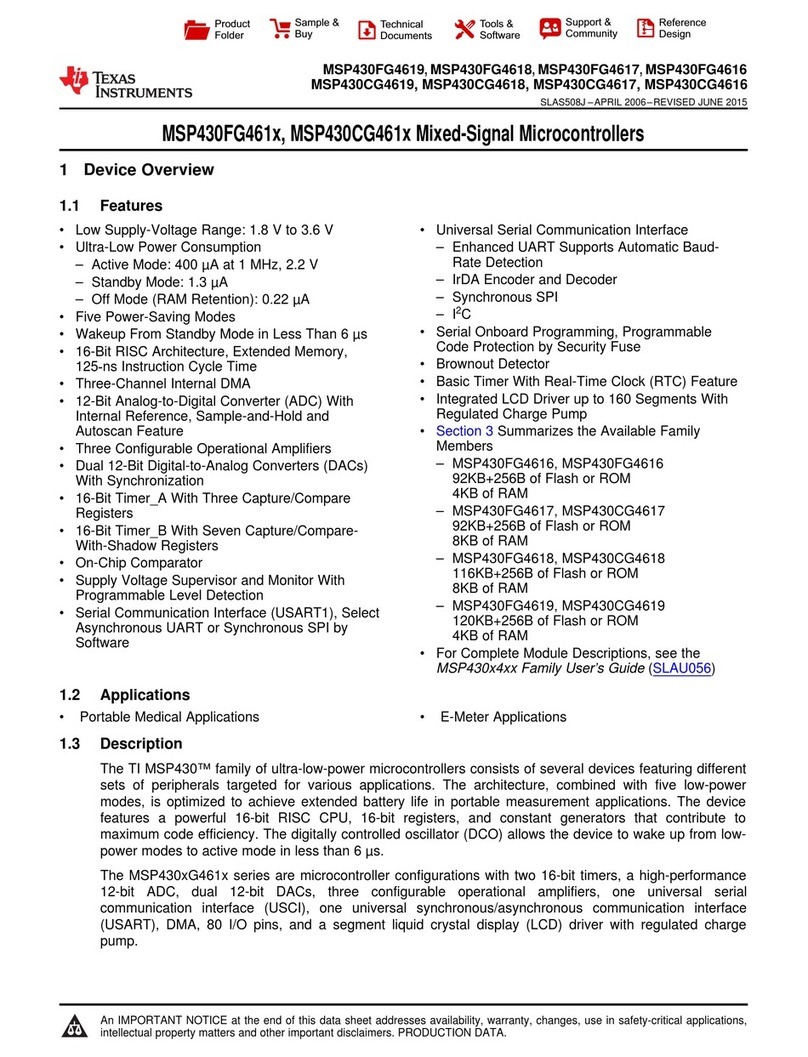
Texas Instruments MSP430FG461x series User manual
Texas Instruments
Texas Instruments CDT370 User manual
Texas Instruments
Texas Instruments Errata MSP430F6736A User manual
Texas Instruments
Texas Instruments TMS320DM357 User manual
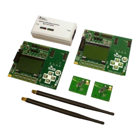
Texas Instruments
Texas Instruments CC1125 User manual
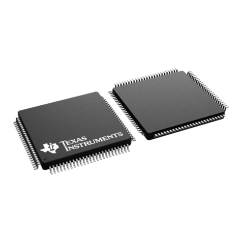
Texas Instruments
Texas Instruments MSP430F6747 User manual
Texas Instruments
Texas Instruments MSP430 series User manual

Texas Instruments
Texas Instruments Chipcon Products CC1110DK User manual
Texas Instruments
Texas Instruments TMS570LS12x User manual
Texas Instruments
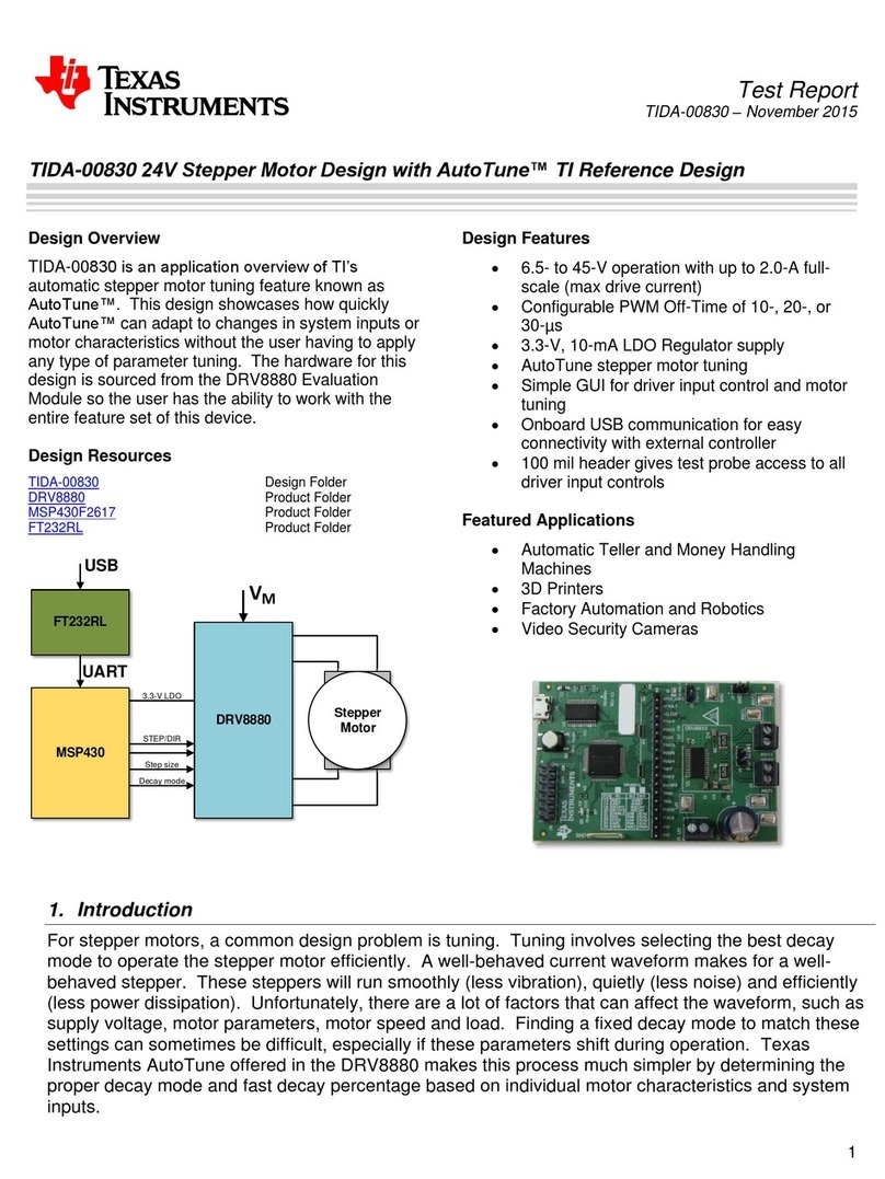
Texas Instruments TIDA-00830 User manual
Texas Instruments
Texas Instruments Serial Programming Adapter MSP430 User manual
Texas Instruments
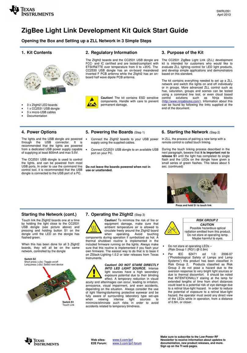
Texas Instruments SWRU351 User manual
Texas Instruments
Texas Instruments MSP430FG6626 User manual
Texas Instruments
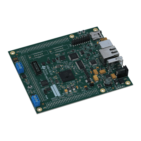
Texas Instruments RM48 series Product manual
Texas Instruments
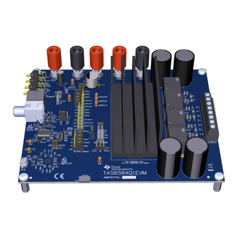
Texas Instruments TAS6584-Q1 EVM User manual
Texas Instruments
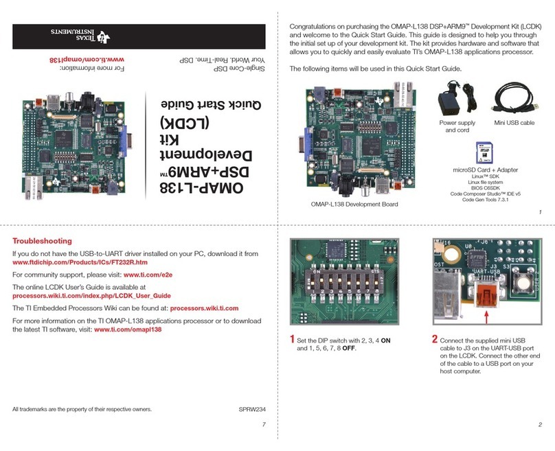
Texas Instruments OMAP-L138 DSP + ARM9 User manual
Texas Instruments
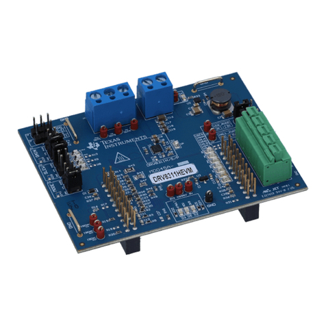
Texas Instruments DRV8311HEVM User manual
Texas Instruments
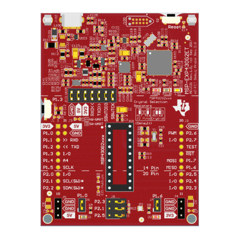
Texas Instruments LaunchPad MSP430G2553 User manual
Texas Instruments
Texas Instruments Vision SDK Linux User manual
Popular Microcontroller manuals by other brands

Novatek
Novatek NT6861 manual

Espressif Systems
Espressif Systems ESP8266 SDK AT Instruction Set

Nuvoton
Nuvoton ISD61S00 ChipCorder Design guide

STMicrolectronics
STMicrolectronics ST7 Assembler Linker user manual

Lantronix
Lantronix Intrinsyc Open-Q 865XR SOM user guide

NEC
NEC 78GK0S/K 1+ Series Application note

