manuals.online logo
Brands
  1. Home
  2. •
  3. Brands
  4. •
  5. Thiele
  6. •
  7. Safety Equipment
  8. •
  9. Thiele TWN 0798 User manual

Thiele TWN 0798 User manual

MOUNTING INSTRUCTIONS
SELF-LOCKING HOOKS
GRADES 80 AND 100
THIELE GmbH & Co. KG
# change indicator
www.thiele.de | [email protected]e
B11092-A
replaces -
© All rights reserved.
US 01.2020
1 | 6
Eye type
TWN 0798
TWN 1836
Clevis type
TWN 0799
TWN 1837
The following Mounting Instructions must always be
followed to avoid the risk of personal injury or property
damage.
Do not use a self-locking hook before reading these
Mounting Instructions.
1. ABOUT THIS INSTRUCTION
This Mounting Instructions describes in particular how self-
locking hooks according to TWN 0798 grade 80, TWN 0799
grade 80, TWN 1836 grade 100 and TWN 1837 grade 100 (TWN
= THIELE Shop Standard) are to be safely used for lifting
purposes.
The instructions apply analogously to components of identical
design.
To comply with these instructions is essential to help avoid
hazards and increases the reliability and service life of the self-
locking hook.
DANGER! Indicates a hazardous
situation which, if not avoided, will
result in death or serious injury.
WARNING! Indicates a hazardous
situation which, if not avoided, could
result in death or serious injury.
CAUTION! Indicates a hazardous
situation which, if not avoided, could
result in minor or moderate injury.
NOTICE! Is used to address practices
not related to physical injury.
Safety Instructions signs indicate
specific safety-related instructions or
procedures.
Chains and accessories marked with the American nominal
size 7/32” already corresponded to European nominal size 6
mm. In order to achieve a better match, the previous nominal
size 7/32" is now converted to the new nominal size 15/64”.
The Working Load Limits have now also been adjusted.
Definitions
Clevis
A U-shaped fitting with pin.
Working Load Limit (WLL)
The maximum load, which a self-locking hook is designed to
support.
Read ASME B30.10 „Hooks“.
Read ASME B30.26 “Rigging Hardware”,
Chapters 26-0, 26-1, 26-4.
2. BASIC SAFETY REQUIREMENTS
To prevent the risk of injury never walk or stay under lifted
loads!
The Working Load Limit must not be exceeded!
Self-locking hooks as well as lifting and attachment means
to be used must be free from defects!
Working under the influence of drugs, medications
impairing the sense and/or alcohol is strictly forbidden!
•Operators, fitters and maintenance personnel must in
particular observe the Mounting and Operating Instructions
as well as standards ASTM A 906/A 906 M (Standard
Specification for Grade 80 and Grade 100 Alloy Steel Chain
Slings for Overhead Lifting), ASTM A 952/A 952 M (Standard
Specification for Forged Grade 80 and Grade 100 Steel
Lifting Components and Welded Attachment Links), ISO
3056 (Non-calibrated round steel link lifting chain and chain
slings; Use and maintenance), ISO 7593 (Chain slings
assembled by methods other than welding; Grade T(8)) and
ISO 4778 (Round steel short link chains for lifting purposes –
Chains slings of welded construction –Grade 8), ISO 1837
Lifting hooks - Nomenclature.
•The specific safety and operating regulations and standards
issued locally in the country where the items are used must
be observed.
MOUNTING INSTRUCTIONS
SELF-LOCKING HOOKS
GRADES 80 AND 100
THIELE GmbH & Co. KG
# change indicator
www.thiele.de | [email protected]e
B11092-A
replaces -
© All rights reserved.
US 01.2020
2 | 6
•The directions given in these Mounting Instructions and
specified documentations relating to safety, assembly,
operation, inspection, and maintenance must be made
available to persons operating and using the self-locking
hooks.
•Make sure these Mounting Instructions are available in a
place near the product during the time the equipment is
used. Please contact the manufacturer if replacements are
needed. Also see chapter 12.
•During operation work, wear your personal protective
equipment!
•Improper assembly and use may cause personal injury
and/or damage to property.
•Assembly and removal as well as inspections and
maintenance must exclusively be carried out by skilled and
authorized persons only.
•Structural changes are impermissible (e.g. welding,
bending).
•Operators must carry out a visual inspection and, if
necessary, a functional test of the safety equipment
before each use.
•Never use worn-out, bent or damaged self-locking hooks.
•Only lift loads that do not exceed the Working Load Limit of
the sling chain assembly.
•Never expose self-locking hooks to loads exceeding the
specified Working Load Limit.
•Make sure the load can take the forces to be applied
without suffering deformation.
•Do not use force when mounting/positioning the self-
locking hooks.
•Do not tip-load a hook.
•Avoid bending loads to act on chain links and self-locking
hooks.
•Always monitor a suspended load.
•Only lift loads that are freely movable and not attached or
fastened.
•Safety elements must not be stressed or strained
operationally.
•Use only shortening/grab hooks or claws for chain
shortening purposes.
•Do not start lifting before you have made sure the load has
been correctly attached and balanced.
•No one including you (operator) must be in the way of the
moving load (hazard area).
•During lifting make sure your hands or other body parts do
not come into contact with lifting means. Only remove
lifting means manually (use your hands).
•Avoid impacts, e.g. due to abruptly lifting loads with a hook
in slack condition.
•Never move a suspended load over persons.
•Never cause suspended loads to swing.
•Self-locking hooks must only be loaded at their base, never
at their nose.
•Avoid impacts, e.g. due to abruptly lifting loads with chain
in slack condition.
•Do not operate the system without fully functioning safety
devices (cotters, spring pins, catch).
•Loads must only be lifted when the hooks are in a locked
position.
•Self-locking hooks must be allowed to move freely in all
tensile directions.
•Put the load only down in flat places/sites where it can be
safely deposited.
•In the event of doubts or concerns about the proper and
safe use, inspection, maintenance or similar things contact
your safety officer or the manufacturer.
THIELE is not responsible for damage caused by non-
observance of the instructions, rules, standards and notes
indicated!
As regard grade 100, THIELE does not give its approval to the
assembly of components sourced from different
manufacturers!
As a rule, self-locking hooks are not permitted for the
transportation of persons.
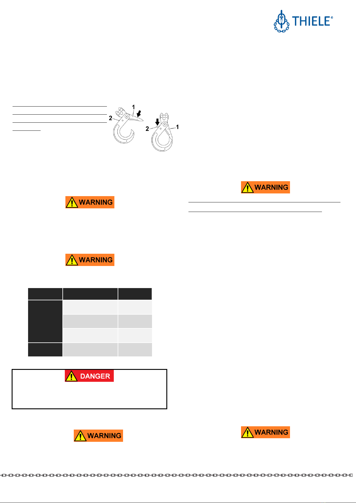
3. DESCRIPTION AND INTENDED USE
Self-locking hooks are exclusively intended for the usage in
chain sling assemblies according to ASTM A 906/A 906M.
The connection to the sling chain is made directly by the clevis
or indirectly by using connecting links which are assembled to
the eye.
Self-locking hooks must exclusively be used
•within the limits of their permissible Working Load Limits,
•within the temperature limits prescribed,
•for permissible attachment methods and sling angles,
•by trained and authorized personnel,
•with original connecting bolts and pins of the specified size.
Failure to do so may cause serious injury or property damage.
Self-locking hooks meet EG Machinery Directive 2006/42/EC
requirements and feature a safety factor of at least 4 based on
the Working Load Limit.
MOUNTING INSTRUCTIONS
SELF-LOCKING HOOKS
GRADES 80 AND 100
THIELE GmbH & Co. KG
# change indicator
www.thiele.de | [email protected]e
B11092-A
replaces -
© All rights reserved.
US 01.2020
3 | 6
They are signed with the corresponding chain size, grade,
manufacturer’s symbol and traceability code.
THIELE self-locking hooks are designed to withstand 20,000
dynamic load cycles under maximum load conditions. In the
event of higher loads (e.g. multi-shift/automatic operation) the
Working Load Limit must be reduced.
Self-locking hooks can also be used within lashing chain
assemblies. When used within a lashing system the maximum
lashing capacity is obtained by doubling the Working Load
Limit.
Any alternating use for lifting and lashing purposes is
impermissible!
4. COMMISSIONING
Prior to using the components for the first time assure that
•the components comply with the order and have not been
damaged,
•test certificates and Mounting Instructions are at hand,
•markings correspond with what is specified in the
documentation,
•inspection deadlines and the qualified persons for
examinations are determined,
•visibility and functional testings are carried out and
documented,
•documentation is safely kept in an orderly manner.
Dispose of the packing in an environmentally compatible way
according to local rule.
5. TECHNICAL DATA
Tables include only article numbers of standard and not
customized parts.
5.1 Self-locking Hooks with Eye, TWN 0798,
Grade 80
Nominal
Size
Article No.
WLL
[lbs.]
Dimensions [mm]
Mass
[lbs.]
E
D
G
H
C
15/64
Z07274
2,500
107
22
28
22
18
1.10
5/16
Z07275
3,500
133
24
33
25
23
1.76
3/8
Z07276
7,100
167
32
45
34
27
3.31
1/2
Z07277
12,000
208
39
52
40
34
7.16
5/8
Z07278
18,100
254
49
64
53
43
13.00
3/4
Z10187
28,300
272
59
77
64
48
16.16
7/8
Z10184
34,200
310
70
92
74
57
21.85
5.2 Self-locking Hooks with Clevis TWN 0799,
Grade 80
Nominal
Size
Article No.
WLL
[lbs.]
Dimensions [mm]
Mass
[lbs.]
E
G
H
C
15/64
Z07279
2,500
98
28
22
18
1.26
5/16
Z07280
3,500
120
33
25
23
2.05
3/8
Z07281
7,100
150
45
34
27
3.86
1/2
Z07282
12,000
185
52
40
34
7.16
5/8
Z07296
18,100
215
64
53
43
16.56
3/4
Z10192
28,300
235
77
64
48
16.05
MOUNTING INSTRUCTIONS
SELF-LOCKING HOOKS
GRADES 80 AND 100
THIELE GmbH & Co. KG
# change indicator
www.thiele.de | [email protected]e
B11092-A
replaces -
© All rights reserved.
US 01.2020
4 | 6
5.3 Self-locking Hooks with Eye TWN 1836,
Grade 100
Nominal
Size
Article No.
WLL
[lbs.]
Dimensions [mm]
Mass
[lbs.]
E
D
G
H
C
15/64
F092203
3,100
110
21
28
20
15
1.10
5/16
F092213
5,700
137
27
36
26
20
1.76
3/8
F092223
8,800
169
35
45
30
26
3.31
1/2
F092233
15,000
209
40
54
41
33
6.61
5/8
F092243
22,600
254
50
62
51
38
13.23
7/8
F092273
42,700
320
70
80
66
52
25.88
5.4 Self-locking Hooks with Clevis TWN 1837,
Grade 100
Nominal
Size
Article No.
WLL
[lbs.]
Dimensions [mm]
Mass
[lbs.]
E
G
H
C
15/64
F092002
3,100
96
28
20
15
1.10
5/16
F092012
5,700
123
36
26
20
1.98
3/8
F092022
8,800
144
45
30
26
3.31
1/2
F092032
15,000
182
54
41
33
6.61
5/8
F092042
22,600
217
62
51
38
13.01
7/8
F092072
42,700
277
80
66
52
27.14
6. ASSEMBLY AND REMOVAL
6.1 General
All components to be installed or used must be in perfect
condition and the relevant Working Load Limits of all parts
must accommodate the respective load to be handled.
Allways assemble/remove components in load-free condition.
Self-locking hooks with eyes are usually attached to chain slings
by means of connecting links. Always observe the mounting
instructions for the connecting links.
6.2 Clevis Fastening System
The clevis fastening system only
permits attachment of the nominal
chain size that suits the attachment
component.
6.2.1 ASSEMBLY
The chain and clevis pin must be of the same rated size.
•Remove the spring pins (1) and (4) as well as clevis pin (3) if
necessary.
•Introduce the end of the chain
between the sides of the clevis
(2).
•Insert the pin (3) sideways into
the clevis and through the final
link of the chain.
•Drive home the spring pins (1)
and (4) so that they sit flush
within their recesses.
The slot must face away from the clevis pin.
•Check that the chain is free to move.
6.2.2 DISASSEMBLY
•Loosen the relevant chain sling.
•Use a mandrel to drive out the spring pins (1/4).
•Remove the pin (3)
•Remove the chain link
Only connect together pins and sling parts of the same grade
(pins Ø 1/2”and over are marked on their face side).
Spring pins are intended for one-off use only.
MOUNTING INSTRUCTIONS
SELF-LOCKING HOOKS
GRADES 80 AND 100
THIELE GmbH & Co. KG
# change indicator
www.thiele.de | [email protected]e
B11092-A
replaces -
© All rights reserved.
US 01.2020
5 | 6
7. OPERATION
To lock the hook, push the top section
(1) down towards the lower section.
When lifting loads do not grasp
between the top and bottom sections
as the hook automatically closes tight
under load.
To open the hook, loosen the chain
sling and press down on the locking
lever (2).
8. CONDITIONS OF USE
8.1 Normal Use
Self-locking hooks must always be freely movable when
attached to the load and must not rest on or be supported by
other structural parts.
8.2 Influence of Temperature
Using self-locking hooks at elevated temperatures will cause
the Working Load Limit to be reduced as indicated below.
Temperature range
Remaining
WLL
Grade 80
-40 °C ≤t ≤205 °C
-40 °F ≤ t ≤ 400 °F
100 %
205 °C < t ≤300 °C
400 °F < t ≤572 °F
90 %
300 °C < t ≤400 °C
572 °F < t ≤752 °F
75 %
Grade 100
-40 °C ≤ t ≤ 205 °C
-40 °F ≤ t ≤ 400 °F
100 %
If the self-locking hooks have been exposed to
temperatures exceeding the maximum values specified
they must not be used furthermore.
8.3 Environmental Influence
Self-locking hooks must not be used in environments where
acids, aggressive or corrosive chemicals or their fumes are
present. Hot-dip galvanizing or a galvanic treatment is
prohibited.
Self-locking hooks are not intended to be used for abrasive
blasting environments.
8.4 Especially Hazardous Conditions
The degree of danger when used in offshore applications, the
lifting of hazardous loads, such as for example liquid metal, or
similar risk potentials must be assessed by a competent person
in the form of a risk analysis. Any additional rules and directives
must be followed in this case.
9. INSPECTION, MAINTENANCE, DISPOSAL
Inspections and maintenance must be arranged by the Owner!
Inspection intervals shall be determined by the Owner!
Visual inspections must be carried out and documented by
competent and trained persons regularly, but at least once a
year or more frequently if the self-locking hooks are in heavy
duty service. After three years at the latest they must
additionally be examined for cracks. A load test is not a
substitute for this examination.
The results of the inspection shall be kept into a file that has to
be set up for each sling chain before first use. The register shall
show characteristic data of the chains and components as well
as identity details.
Immediately stop using self-locking hooks that show the
following defects:
•missing or illegible identification/marking,
•deformation, elongation or fractures of chains or
components,
•cuts, notches, cracks, incipient cracks, pinching,
•heating beyond permissible limit,
•severe corrosion,
•broken springs,
•wear in excess of 10 %, e.g. hook attachment area and pin
diameter,
•excessive play between the top and bottom sections,
•less than 50 % overlap between the top section and the
nose.
Cleaning (e.g. prior to inspections) must not take place by using
flames or methods that might cause hydrogen embrittlement
(e.g. pickling or immersion in acidic solutions).
MOUNTING INSTRUCTIONS
SELF-LOCKING HOOKS
GRADES 80 AND 100
THIELE GmbH & Co. KG
# change indicator
www.thiele.de | [email protected]e
B11092-A
replaces -
© All rights reserved.
US 01.2020
6 | 6
9.1 Inspection Service
THIELE offers inspection, maintenance and repair services
performed by trained and competent personnel.
9.2 Maintenance
Maintenance and repair work must only be performed by
competent and trained persons.
Minor notches and cracks may be eliminated by careful
grinding observing the maximum cross section reduction
requirement of 10 % and avoid making more severe cuts or
scores.
All maintenance and repair activities are to be documented.
10. SPARE PARTS
Use only original spare parts.
10.1 Spare Parts Sets TWN 0967/0
for TWN 0798, TWN 0799
Nominal Size
Article No.
Contents
15/64
F329090
Safety Catch,
Spring,
Spring Pin
5/16
F329190
3/8
F329290
1/2
F329390
5/8
F329490
3/4
F0922056
7/8
F0922056
10.2 Spare Parts Sets TWN 1933/0
for TWN 1837
Nominal Size
Article No.
Contents
15/64
Z10118
Clevis Pin,
Spring Pins
5/16
Z10119
3/8
Z10120
1/2
Z10121
5/8
Z10122
7/8
Z10125
10.3 Spare Parts Sets TWN 1935
for TWN 1836, TWN 1837
Nominal Size
Article No.
Contents
15/64
Z10110
Safety Catch,
Spring,
Spring Pin
5/16
Z10111
3/8
Z10112
1/2
Z10113
5/8
Z10114
7/8
Z10117
11. STORAGE
Self-locking hooks must be stored properly sorted and in dry
conditions at temperatures between 32 °F and 104 °F.
Do not store in a manner that cause mechanical damage.
12. THIELE OPERATING AND MOUNTING
INSTRUCTIONS
Current mounting and operating instructions are available as a
PDF download on the THIELE-website www.thiele.de.
13. PUBLISHING INFORMATION
KWS Inc.
P.O. Box 470487, Tulsa, OK 74147, USA
Phone number 800-872-9313
Fax 918-665-4118
Email [email protected]
Manufacturer:
THIELE GmbH & Co. KG
Werkstraße 3, 58640 Iserlohn, Germany
Phone number +49 2371/947-0
Email [email protected]

This manual suits for next models

3

Other Thiele Safety Equipment manuals

Thiele TWN 0812 User manual

Thiele

Thiele TWN 0812 User manual

Thiele TWN 0868 User manual

Thiele

Thiele TWN 0868 User manual

Thiele TWN 0121/1 User manual

Thiele

Thiele TWN 0121/1 User manual

Thiele TWN 0827/1 User manual

Thiele

Thiele TWN 0827/1 User manual

Thiele TWN 0827/1 User manual

Thiele

Thiele TWN 0827/1 User manual

Thiele Grade 80 User manual

Thiele

Thiele Grade 80 User manual

Thiele GRADES 8 User manual

Thiele

Thiele GRADES 8 User manual

Thiele TWN 0121/1 User manual

Thiele

Thiele TWN 0121/1 User manual

Thiele TWN 0827/1 User manual

Thiele

Thiele TWN 0827/1 User manual

Thiele TWN 0827/1 User manual

Thiele

Thiele TWN 0827/1 User manual

Thiele Streamfeeder Pro Series User manual

Thiele

Thiele Streamfeeder Pro Series User manual

Thiele TWN 0850/2 User manual

Thiele

Thiele TWN 0850/2 User manual

Thiele Grade 100 User manual

Thiele

Thiele Grade 100 User manual

Popular Safety Equipment manuals by other brands

Napier SPORTZ 44444 installation instructions

Napier

Napier SPORTZ 44444 installation instructions

DAVES MEDICAL Xdcuff 102 user guide

DAVES MEDICAL

DAVES MEDICAL Xdcuff 102 user guide

ECOSAFE DLP62 instruction manual

ECOSAFE

ECOSAFE DLP62 instruction manual

Petzl CORDEX 2133 manual

Petzl

Petzl CORDEX 2133 manual

SafeWaze 019-8016 user manual

SafeWaze

SafeWaze 019-8016 user manual

Petzl IGUANE TECHNICAL NOTICE

Petzl

Petzl IGUANE TECHNICAL NOTICE

Dräger PSS 5000 Series Instructions for use

Dräger

Dräger PSS 5000 Series Instructions for use

Guardian FABXR instruction manual

Guardian

Guardian FABXR instruction manual

Metasys B110LP manual

Metasys

Metasys B110LP manual

S&S Precision CR-M CRM-0001 Series User instructions

S&S Precision

S&S Precision CR-M CRM-0001 Series User instructions

CAMP GYRO1 manual

CAMP

CAMP GYRO1 manual

Globestock G.Stop 500 Series Service manual

Globestock

Globestock G.Stop 500 Series Service manual

Safety 1st HS129 manual

Safety 1st

Safety 1st HS129 manual

ERGODYNE SQUIDS quick start guide

ERGODYNE

ERGODYNE SQUIDS quick start guide

DUI WEIGHT & TRIM III owner's manual

DUI

DUI WEIGHT & TRIM III owner's manual

MSA M1 Basic Manual

MSA

MSA M1 Basic Manual

Beghelli 19308 manual

Beghelli

Beghelli 19308 manual

Dräger Oxyboks KT Instructions for use

Dräger

Dräger Oxyboks KT Instructions for use

manuals.online logo
manuals.online logoBrands
  • About & Mission
  • Contact us
  • Privacy Policy
  • Terms and Conditions

Copyright 2025 Manuals.Online. All Rights Reserved.