TJM T15 User manual

FITTING INSTRUCTIONS
Product:
T15 Fleet Frontal Protection System
Vehicle:
Isuzu D-Max, Isuzu Mu-X
Part No.
070SB15F34E
For product warranty please refer to our website www.tjm.com.au
File: F-4959
Page 1 of 17
24/10/2022
Australian Standards Relating to Installing Vehicle Frontal Protection Systems (VFPS): AS 4876.1-2002
a) Do not attach V.F.P.S. to vehicle using anchorages not intended for this purpose (e.g. engine mounting bolts), other than those
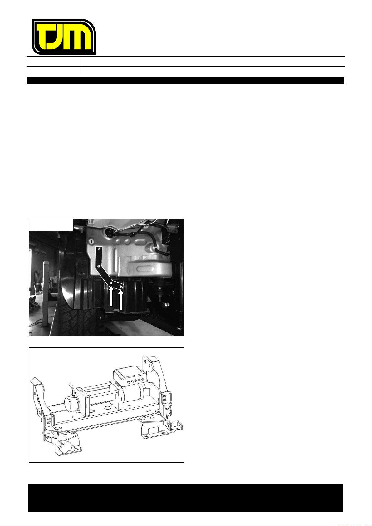
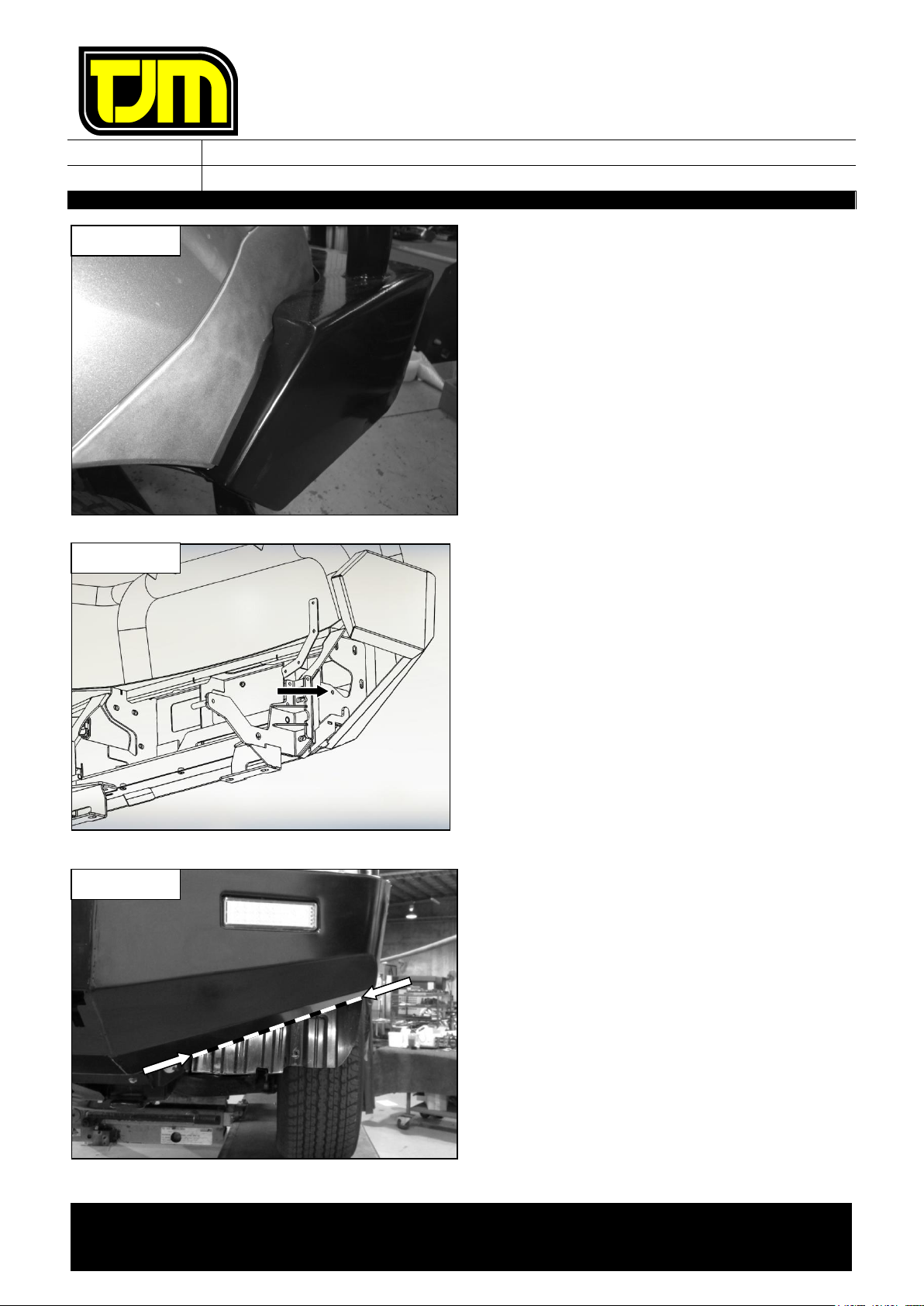
specified by the V.F.P.S. manufacturer in this instruction.
b) Do not use this product for any vehicle make or model other than those specified by the V.F.P.S. manufacturer (as above).
c) Do not remove any plaques or labels from the V.F.P.S.
d) Do not modify the structure of the V.F.P.S. in any way.
•Before commencing fitment read instructions and ensure all listed components
are supplied.
•Estimated Fitting Time: 4hrs (4.5hrs for winch provisions)
•Left hand & right hand components are determined as seated in the vehicle.
•The fitment of TJM products does not nullify the OE manufacturer's operating
guidelines and/or warnings. Ensure you are familiar with and adhere to the usage
instructions specified by the manufacturer in the owner's manual or other official
documentation.
•Check for (and remove) any build up in all threads fitted to the product.
•When fitting accessories to TJM products (ie. driving lights and aerials), ensure
suitable washer plates are used under the mounting surface that allow the
accessory to be secured in a way that prevents it from damaging the product.
•Where OE air guides require trimming, ensure minimal clearance between air
guides and TJM components to prevent air leakage which may adversely affect
vehicle cooling.
•When removing protective coatings, ensure all new edges are deburred, clean any
swarf from the area and apply rust preventative to exposed surfaces.
•Always place the product on a soft work space to prevent damage prior to
installation.
Bolt tensions
Dia. (mm)
Nm
ft.lbs
Dia. (inch)
Nm
ft.lbs
All bolt tensions
are as follows
unless otherwise
specified.
5
5
4
1/4”
9
7
6
9
7
5/16”
22
15
8
22
16
3/8”
33
27
10
44
32
7/16”
55
43
12
77
57
1/2”
86
66

FITTING INSTRUCTIONS
Product:
T15 Fleet Frontal Protection System
Vehicle:
Isuzu D-Max, Isuzu Mu-X
Part No.
070SB15F34E
For product warranty please refer to our website www.tjm.com.au
File: F-4959
Page 2 of 17
24/10/2022
ITEM
NO.
Description
Qty
Part
Number
PARTS LIST
1
Outback FPS
1
F-4346
2
Winch Frame
1
F-1759
FITTING KIT
3
Chassis Mount LH
1
F-1760L
4
Chassis Mount RH
1
F-1760R
5
Support Plate
2
F-1854
6
Spacer Tube (M10 x 54.5mm Long)
2
F-1855
7
Spacer Tube (M10 x 66mm Long)
2
F-1931
8
Winch Frame Cover
1
F-1802
9
Inner Guard Support
2
F-2168
10
LED Indicator / Park Light
2
92750
N/A
Pinch-Weld (2600mm Long)
1
K3219
N/A
Bumper Trim Template
1
F-14862-T1
N/A
Plug’n’Play wiring loom
1
92630
BOLT KIT
N/A
M6 x 1.0 x 16mm Hex Head Screw
4
K1232
N/A
M6 x 1.0 x 30mm Hex Head Bolt
4
K0706
N/A
M6 x 1.0 Nyloc Nut
6
K0605
N/A
M6 Spring Washer
2
K0915
ITEM
NO.
Description
Qty
Part
Number
BOLT KIT (cont’d)
N/A
M6 x Ø18mm Flat Washer
14
-
N/A
M8 x 1.25 x 20mm Hex Head Bolt
4
K0552
N/A
M8 x 1.25 x 30mm Hex Head Bolt
5
K0554
N/A
M8 x 1.25 Flange Nut
4
K3035
N/A
M8 Spring Washer
5
K0620
N/A
M8 x Ø 28mm Flat Washer
9
-
N/A
M10 x 1.25 x 30mm Hex Head Screw
8
K0564
N/A
M10 x 1.25 x 40mm Hex Head Bolt
4
K0566
N/A
M10 x 1.25 x 80mm Hex Head Bolt
2
K0953
N/A
M10 x 1.25 x 100mm Hex Head Bolt
2
K0962
N/A
M10 x 1.25 Nyloc Nut
10
K3099
N/A
M10 Spring Washer
6
K0621
N/A
M10 x Ø30mm Flat Washer
24
WSST-W13
N/A
3/8” x Ø1” Flat Washer
2
K0630
N/A
M12 x 1.25 x 30mm Hex Head Bolt
12
K0569
N/A
M12 x 1.25 Nyloc Nut
12
K1200
N/A
1/2" x Ø1-1/4” Flat Washer
24
K0623
N/A
M16 x 1.5 x 50mm Hex Head Bolt
2
K0910
N/A
M16 x 1.5 Nyloc Nut
2
K0637
N/A
M16 x Ø30mm Flat Washer
4
K0898
N/A
Nylon Plug
4
K0665

FITTING INSTRUCTIONS
Product:
T15 Fleet Frontal Protection System
Vehicle:
Isuzu D-Max, Isuzu Mu-X
Part No.
070SB15F34E
For product warranty please refer to our website www.tjm.com.au
File: F-4959
Page 3 of 17
24/10/2022
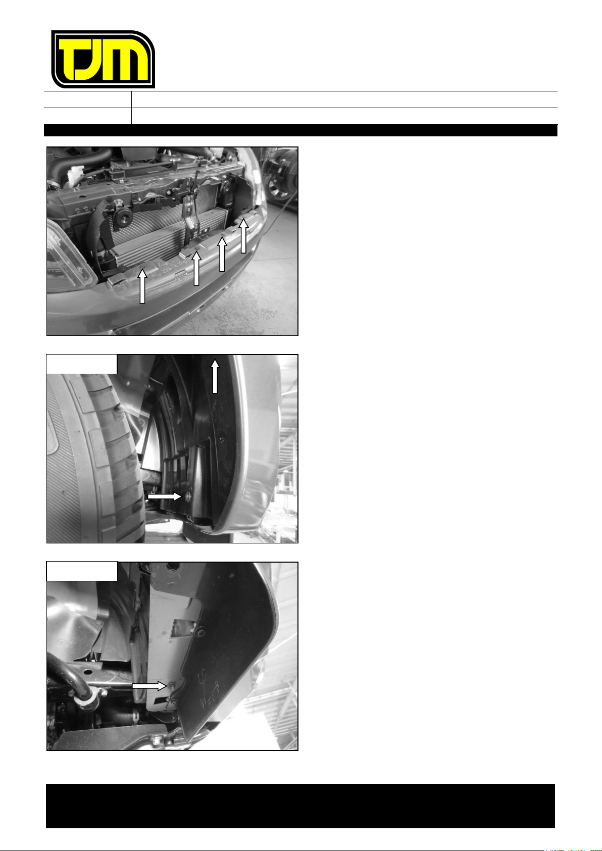
1. Remove (& retain) the number-plate,
discarding the fasteners.
2. Remove (& retain) the clips (4) that are
securing the top of the grille/radiator shroud.
3. Remove (& retain) the screw (1), from under
the Isuzu badge on the front of the
grille/radiator shroud.
4. Remove (& retain) the grille/radiator shroud,
by pulling it firmly forwards from the vehicle,
then carefully set it aside.
FITTING INSTRUCTIONS
Product:
T15 Fleet Frontal Protection System
Vehicle:
Isuzu D-Max, Isuzu Mu-X
Part No.
070SB15F34E
For product warranty please refer to our website www.tjm.com.au
File: F-4959
Page 4 of 17
24/10/2022
5. Remove (& retain) the clips (4) from the top of
the lower bumper.
6. Remove (& retain) the upper screw (1), from
inside the wheel arch, securing the top of the
bumper.
7. Remove (& discard) the lower screw (1), from
inside the wheel arch.
8. Remove (& discard) the nut (1) from under
the bumper, behind the lower skirt.
9. Repeat the three previous steps for the
opposite side of the vehicle.
10. Disconnect the fog-lights wiring harness from
the vehicle.
The OE fog-lights (& harness) are not
required for the installation of this FPS.
RHS SHOWN
RHS SHOWN
FITTING INSTRUCTIONS
Product:
T15 Fleet Frontal Protection System
Vehicle:
Isuzu D-Max, Isuzu Mu-X
Part No.
070SB15F34E
For product warranty please refer to our website www.tjm.com.au
File: F-4959
Page 5 of 17
24/10/2022
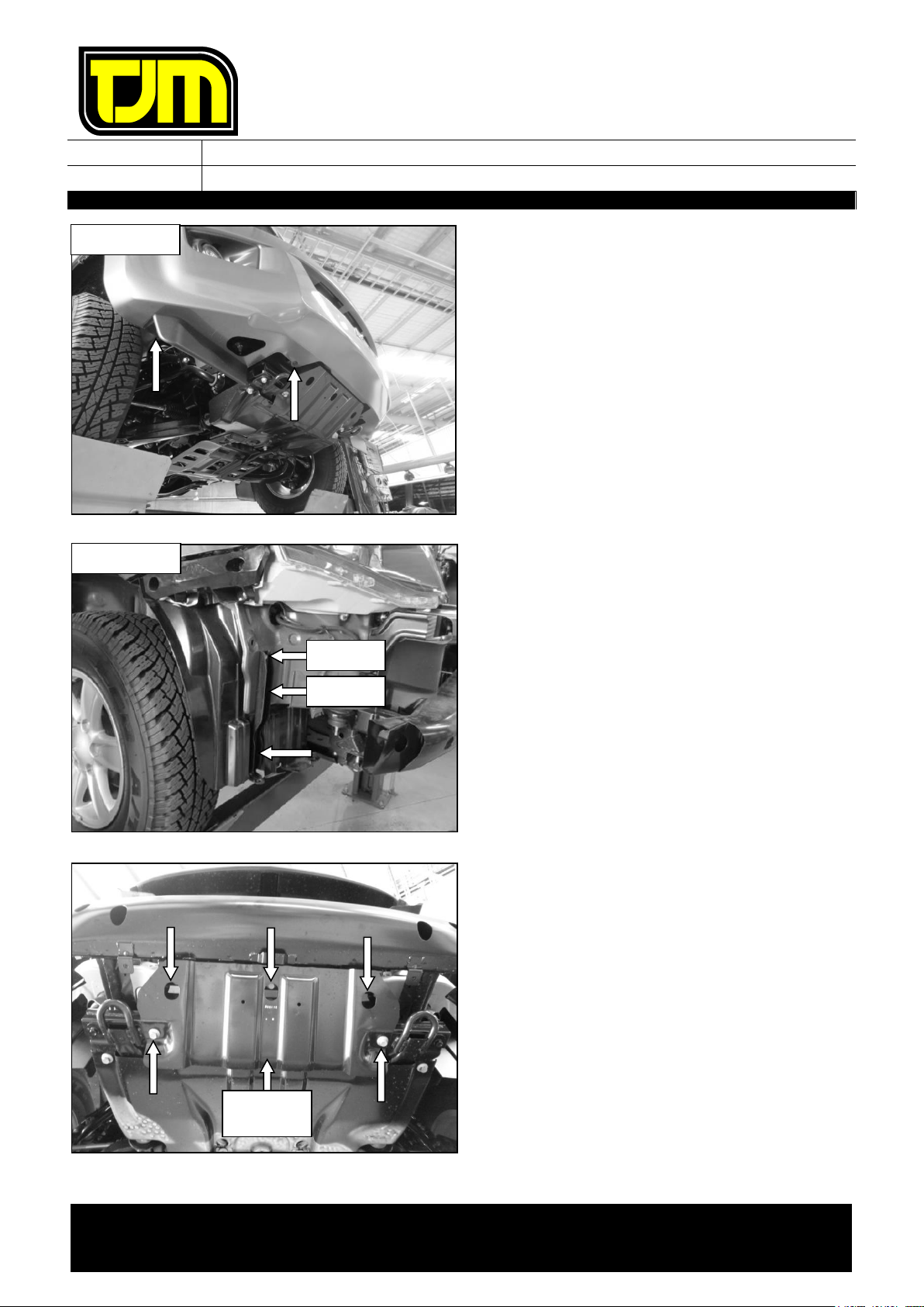
11. Remove (& retain) the clips (4) from the
underside of the bumper.
12. On both sides of the vehicle, gently pull the
bumper assembly outwards from the vehicle,
so as to release the sides of the bumper
assembly from the vehicle.
13. Remove (& retain) the bumper assembly from
the vehicle & carefully set it aside.
14. On each side of the vehicle, remove (&
discard) the OE inner guard support, retaining
the indicated fasteners, whilst discarding the
rest.
15. Remove (& retain) the small steering guard
from the vehicle, discarding the fasteners (5).
RHS SHOWN
RHS SHOWN
STEERING
GUARD
RETAIN
RETAIN

FITTING INSTRUCTIONS
Product:
T15 Fleet Frontal Protection System
Vehicle:
Isuzu D-Max, Isuzu Mu-X
Part No.
070SB15F34E
For product warranty please refer to our website www.tjm.com.au
File: F-4959
Page 6 of 17
24/10/2022
16. Remove (& discard) the fasteners (2) that are
securing the tow points to the chassis cross-
member.
17. Remove (& retain) the large steering guard
from the vehicle, retaining the fasteners (4).
18. Loosen, but do not remove, the indicated
fasteners (2), so as to allow the front of the
tow points to drop slightly.
19. Remove (& discard) the front intrusion beam,
retaining the indicated lower fasteners (2),
whilst discarding the rest.
FRONT INTRUSION
BEAM
STEP 16
STEP 17
RETAIN
RETAIN

FITTING INSTRUCTIONS
Product:
T15 Fleet Frontal Protection System
Vehicle:
Isuzu D-Max, Isuzu Mu-X
Part No.
070SB15F34E
For product warranty please refer to our website www.tjm.com.au
File: F-4959
Page 7 of 17
24/10/2022
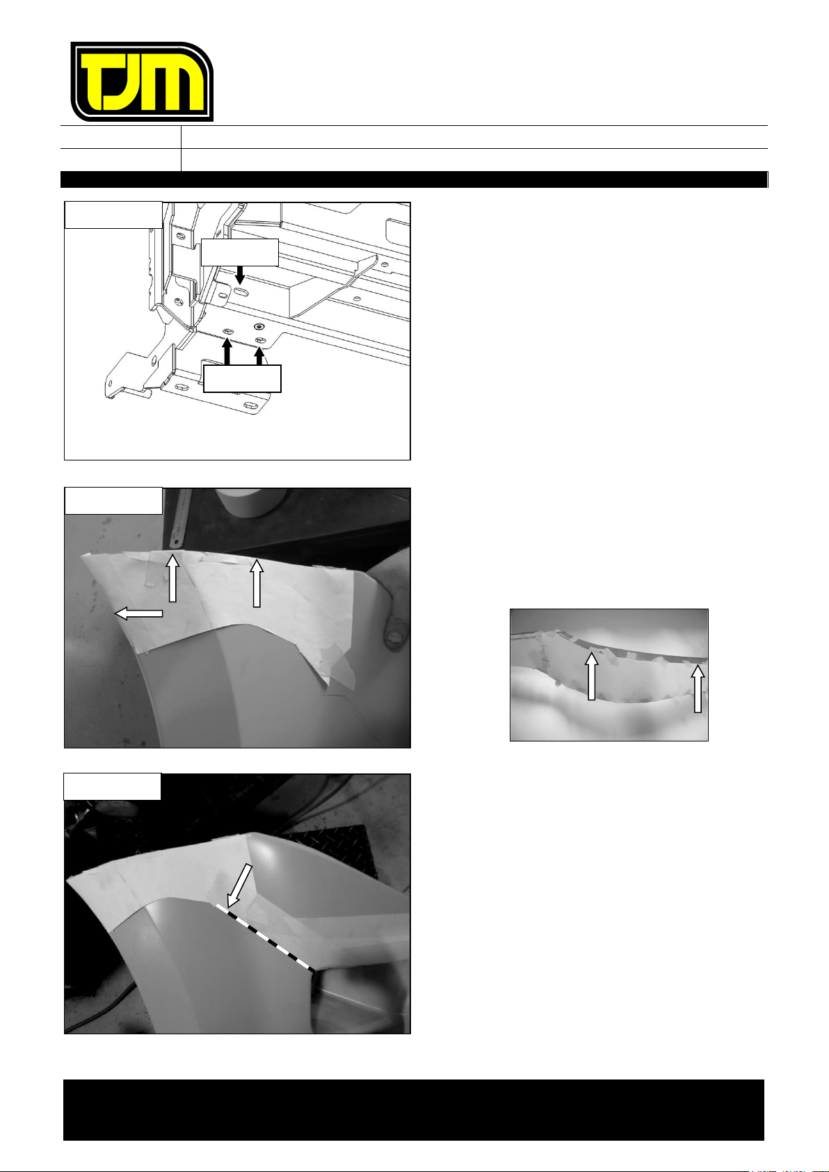
20. Remove (& discard) the center bumper
supports (& fasteners).
21. Position the chassis mount on the chassis rail
as shown, with the lower face positioned
between the chassis cross-member & the tow
point.
22. Through the tow point, loosely secure the
bottom of the chassis mount in place, at the
location made available in step 16, using an
M10 x 1.25 x 40mm hex bolt (1), M10 x
Ø30mm flat washer (1) & M10 spring washer
(1).
23. Loosely secure the chassis mount in place,
using an M16 x 1.5 x 50mm hex bolt (1), M16
x Ø30mm flat washers (2) & M16 nyloc nut
(1).
24. Position an M10 x 1.25 x 100mm hex bolt (1)
& M10 x Ø30mm flat washer (1) at the
indicated location.
25. Position an M10 x 66mm long tube spacer
over the fastener from the previous step, then
loosely secure the rear of the chassis mount in
place, using the fasteners from the previous
step, an M10 x Ø30mm flat washer (1) & M10
nyloc nut (1).
RHS SHOWN
RHS SHOWN
STEP 24
STEP 23
STEP 22

FITTING INSTRUCTIONS
Product:
T15 Fleet Frontal Protection System
Vehicle:
Isuzu D-Max, Isuzu Mu-X
Part No.
070SB15F34E
For product warranty please refer to our website www.tjm.com.au
File: F-4959
Page 8 of 17
24/10/2022
26. Positioning the support plate as shown, secure
the chassis mount in place, using an M10 x
1.25 x 80mm hex bolt (1), M10 x Ø30mm flat
washers (2), M10 nyloc nut (1) & M10 x 54mm
long tube spacer.
Ensure that the spacer plate is
accurately aligned with the chassis
mount edges.
27. Starting with the fastener installed in step 22,
secure all of the previously installed fasteners
to the specified torque settings listed on page
1, including the fasteners from step 18.
28. Repeat steps 21 through to 27 for the
opposite side of the vehicle.
29. Drill Ø8mm holes through the support plate,
using the indicated holes as a guide.
30. De-burr the holes & clean the areas/surfaces
of any swarf/debris, then treat the raw
exposed surfaces with a rust preventative.
31. Secure through the holes drilled in step 28,
using M8 x 1.25 x 20mm hex bolts (2), M8 x
Ø28mm flat washers (2) & M8 flange nuts (2).
32. Repeat steps 29 through to 31 for the
opposite side of the vehicle.
33. Position the winch frame on the chassis
mounts & loosely secure it in place, using the
fasteners listed below:
33.1. M10 x 1.25 x 30mm hex bolts (4), M10
nyloc nuts (4) & M10 x Ø30mm flat
washers (8)
33.2. M12 x 1.25 x 30mm hex bolts (2), M12
nyloc nuts (2) & 1/2" x Ø1-1/4” flat
washers (4).
RHS SHOWN
PLATE
STEP 26
RHS SHOWN
STEP 33.2
STEP 33.1
RHS SHOWN
FITTING INSTRUCTIONS
Product:
T15 Fleet Frontal Protection System
Vehicle:
Isuzu D-Max, Isuzu Mu-X
Part No.
070SB15F34E
For product warranty please refer to our website www.tjm.com.au
File: F-4959
Page 9 of 17
24/10/2022
34. Loosely secure the winch frame in place, using
the fasteners listed below:
34.1. M10 x 1.25 x 30mm hex bolts (2), M10
spring washers (2), and 3/8” x Ø1” Flat
Washers (2).
34.2. M12 x 1.25 x 30mm hex bolts (4), M12
nyloc nuts (4) & 1/2" x Ø1-1/4” flat
washers (8).
35. Trim the supplied bumper trim template to
shape (appropriate to the vehicle model) &,
aligning it with the indicated edges, tape it in
place.
The second part of the template is only
required if fitting to an M-UX.
Steps 36 & 37 only apply to a D-Max.
Otherwise, please proceed to step 38.
36. Following the indicated edge on the bumper
trim template, tape a trim line down to the
outer upper corner of the fog-light recess.
RHS SHOWN
STEP 34.1
STEP 34.2
RHS SHOWN
RHS SHOWN

FITTING INSTRUCTIONS
Product:
T15 Fleet Frontal Protection System
Vehicle:
Isuzu D-Max, Isuzu Mu-X
Part No.
070SB15F34E
For product warranty please refer to our website www.tjm.com.au
File: F-4959
Page 10 of 17
24/10/2022
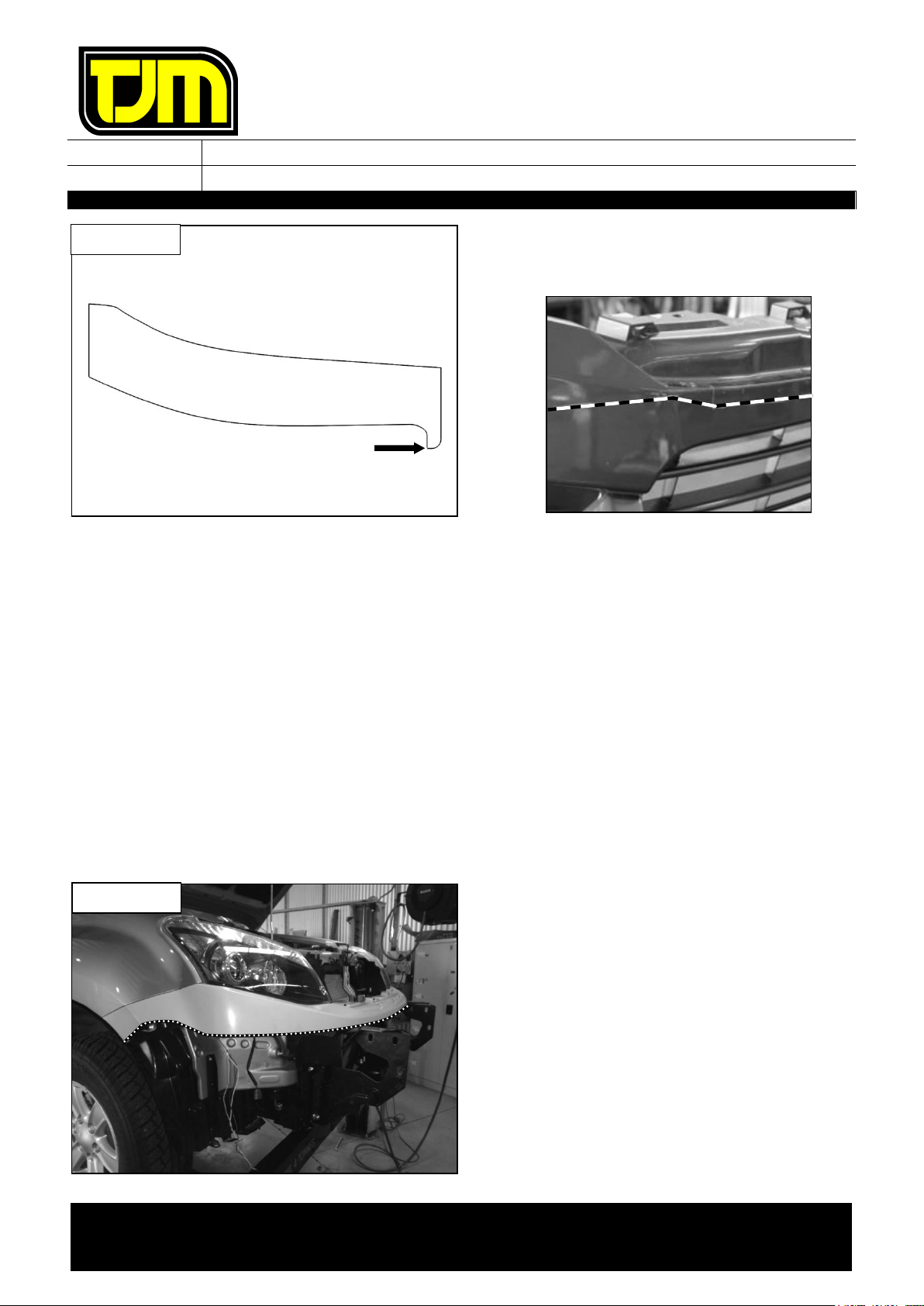
37. Mark a parallel line 45mm up from the
indicated edge, then extend it out to the trim
line generated in the previous step.
Steps 38 through to 42 only apply to an M-
UX. Otherwise, please proceed to step 43.
38. Mark a parallel line 20mm below the indicated
edge, extend the line out to the end of the
grille recess.
39. From the corner of the grille recess (point A),
mark a point 10mm down (point B).
40. From point A, measure in 57mm along the
contour of the grille recess, then measure
down to the trim line created in step 38 and
mark point C.
41. Mark a trim line between points B & C.
45mm
RHS SHOWN
10mm
(POINT B)
57mm
POINT A
POINT C
RHS SHOWN
FITTING INSTRUCTIONS
Product:
T15 Fleet Frontal Protection System
Vehicle:
Isuzu D-Max, Isuzu Mu-X
Part No.
070SB15F34E
For product warranty please refer to our website www.tjm.com.au
File: F-4959
Page 11 of 17
24/10/2022
42. From the indicated corner on the MU-X
template, mark a straight trim line to the
previously marked point B.
43. Once the relevant trim lines have been
marked, repeat the process on the opposite
side of the vehicle.
44. Trim the bumper assembly to shape along the
previously created trim lines & discard the
lower section.
It is suggested that a reciprocating saw
with a fine toothed blade (or similar) is
used to perform the above step.
45. De-burr the edges & clean the area/surface of
any swarf debris.
46. Re-fit the upper section of the bumper to the
vehicle, using the fasteners retained in steps 5
& 6.
47. Re-fit the grille/radiator shroud to the vehicle,
using the fasteners retained in steps 2 & 3.
48. Fit the pinch-weld along the trimmed edge of
the bumper, indicated by the dotted lines.
49. Trim off and excess from the ends of the pinch
weld.
50. Use super-glue at the ends of the pinch-weld
and at any significant curves, so as to ensure
that it does not come away from the bumper.
RHS SHOWN
RHS SHOWN
FITTING INSTRUCTIONS
Product:
T15 Fleet Frontal Protection System
Vehicle:
Isuzu D-Max, Isuzu Mu-X
Part No.
070SB15F34E
For product warranty please refer to our website www.tjm.com.au
File: F-4959
Page 12 of 17
24/10/2022
51. Measure &, using a marker, identify the centre
of the winch frame such that it is visible when
looking from the front of the vehicle.
52. Using the mark made in the previous step,
centre the winch frame on the vehicle,
according to the Isuzu badge.
Adjust the position of the winch frame
if required.
53. Tighten all of the previously installed fasteners
to the torque settings specified on page 1.
54. Using the fasteners retained in step 14, fit the
inner guard support as shown.
55. Using the indicated holes as a guide, drill two
Ø6mm holes in the plastic inner guard.
56. Secure the inner guard support to the plastic
inner guard, using M6 x 1.0 x 16mm hex
screws (2), M6 x Ø18mm flat washers (4) &
M6 nyloc nuts (2), tightening the fasteners to
the torque settings specified on page 1
57. Repeat steps 54 through to 56 for the
opposite side of the vehicle.
Steps 58 & 59 only apply if a winch is to be
fitted. Otherwise, please proceed to step
60.
58. Locating the winch & control box as shown,
refer to the winch fitting instructions & fit the
winch to the winch frame.
RHS SHOWN

FITTING INSTRUCTIONS
Product:
T15 Fleet Frontal Protection System
Vehicle:
Isuzu D-Max, Isuzu Mu-X
Part No.
070SB15F34E
For product warranty please refer to our website www.tjm.com.au
File: F-4959
Page 13 of 17
24/10/2022
59. Using the fasteners supplied with the winch,
secure the fairlead to the FPS.
60. Positioning the centre cover panel as shown,
secure it in place, using M8 x 1.25 x 30mm
hex bolts (2), M8 spring washers (2) & M8 x
Ø28mm flat washers (2).
61. Secure the centre cover panel in place, using
M6 x 1.0 x 30mm hex bolts (2), M6 nyloc nuts
(2) & M6 x Ø18mm flat washers (4).
62. Re-fit the large steering guard as per its
original installation, using the fasteners from
step 17.
63. Re-fit the small steering guard as per its
original installation, using the fasteners listed
below:
63.1. M8 x 1.25 x 30mm hex bolts (3), M8
spring washers (3) & M8 x Ø28mm flat
washers (3).
63.2. M10 x 1.25 x 40mm hex bolts (2), M10
spring washers (2) & M10 x Ø30mm flat
washers (2).
STEP 63.2
STEP 63.1
STEP 61
STEP 60

FITTING INSTRUCTIONS
Product:
T15 Fleet Frontal Protection System
Vehicle:
Isuzu D-Max, Isuzu Mu-X
Part No.
070SB15F34E
For product warranty please refer to our website www.tjm.com.au
File: F-4959
Page 14 of 17
24/10/2022
64. Tighten the fasteners from steps 60 through
to 63, to the specified torque settings listed on
page 1.
65. Insert the nylon plugs supplied, into the
square cut-outs for the indicator/park lights
(as shown).
66. Remove the backing plate from each
indicator/park light, then secure the backing
plate to the FPS, using the screws provided
with the light assemblies.
67. Supporting the backing plate, re-fit (clip) each
indicator/park light to the backing plate
(ensuring that an adequate seal has been
achieved).
Ensure that the park light is positioned
towards the outside of the vehicle.
68. Gently remove the identified connector from
the rear of the headlight assembly by twisting
anti-clockwise.
Do not touch the indicator bulb whist
performing step 68.
69. Disconnect the plug from the rear of the
indicator bulb retainer.
70. Connect the grey connectors of the plug’n’play
wiring loom as shown.
71. Re-install the indicator bulb retainer to the
headlight assembly.
RHS SHOWN

FITTING INSTRUCTIONS
Product:
T15 Fleet Frontal Protection System
Vehicle:
Isuzu D-Max, Isuzu Mu-X
Part No.
070SB15F34E
For product warranty please refer to our website www.tjm.com.au
File: F-4959
Page 15 of 17
24/10/2022
72. Carry out the same process as above for the
park light on the plug indicated using the
green connectors of the plug’n’play wiring
loom.
73. Repeat steps 69 - 72 for the opposite side of
the vehicle.
74. Route the other end of the wiring loom
through the circular hole in the body panel,
ready to attach once the bar is fitted.
75. With the assistance of another person,
carefully lift the FPS into position on the
chassis mount, then loosely secure it in place,
using M12 x 1.25 x 30mm hex bolts (6), 1/2" x
Ø1-1/4" flat washers (12) & M12 nyloc nuts
(6) at the indicated locations.
RHS SHOWN
RHS SHOWN
FITTING INSTRUCTIONS
Product:
T15 Fleet Frontal Protection System
Vehicle:
Isuzu D-Max, Isuzu Mu-X
Part No.
070SB15F34E
For product warranty please refer to our website www.tjm.com.au
File: F-4959
Page 16 of 17
24/10/2022
76. Align the FPS to the vehicle, ensuring that it is
level & that there is an even gap between the
inner top edge of the FPS & the trimmed
bumper assembly, then tighten the fasteners
from the previous step to the specified torque
settings listed on page 1.
77. Using the indicated hole in the chassis mount
as a template, drill a Ø10mm hole through
both vertical mounts in the FPS.
78. De-burr the hole & clean the areas/surfaces of
any swarf/debris, then treat the raw exposed
surfaces with a rust preventative.
79. With the bolt heads on the inside of the
chassis mount, secure through the holes
drilled in step 77, using M10 x 1.25 x 30mm
hex screws (2), M10 x Ø30mm flat washers
(4) & M10 nyloc nuts (2).
80. Tighten the fasteners from the previous step
to the specified torque settings listed on page
1.
81. Re-connect the indicator/park lights & fog-
lights to the wiring harness.
82. Trim the plastic inner guard to shape, using
the wing under guard as a guide.
83. De-burr the edges & clean the area/surface of
any swarf debris.
84. Position the outer edge of the plastic inner
guard inside the FPS wing return edge.
RHS SHOWN
RHS SHOWN
RHS SHOWN
FITTING INSTRUCTIONS
Product:
T15 Fleet Frontal Protection System
Vehicle:
Isuzu D-Max, Isuzu Mu-X
Part No.
070SB15F34E
For product warranty please refer to our website www.tjm.com.au
File: F-4959
Page 17 of 17
24/10/2022
85. Using M6 x 1.0 x 30mm hex bolts (2), M6
spring washers (2) & M6 x Ø18mm flat
washers (2), secure the number-plate in place
to the front of the FPS.
86. Ensure that all of the relevant wiring
harnesses are connected & check to ensure
that the indicators, park lights, fog-lights,
winch, etc are functioning correctly.
87. Ensure that all of the fasteners are fully
tightened to the specified torque settings &
that, as a results of fitting the product, no
vehicle components are crushed or will chafe.
Other manuals for T15
3
Table of contents
Other TJM Automobile Accessories manuals


Popular Automobile Accessories manuals by other brands


Redrock
Redrock J100176 installation instructions

Let's Go Aero
Let's Go Aero GearDeck H00604 product manual

MetaSystem
MetaSystem Lineaccessori Meta Voice manual

GreenValley
GreenValley WOLLEMI Installation and usage instructions

HI-POD
HI-POD JS7A/2010 Instructions for installation & use

Menabo
Menabo QUASAR 320 Fitting instructions