TJM T13 User manual

FITTING INSTRUCTIONS
Product:
T13 Outback Frontal Protection System
Vehicle:
Ford Ranger PXIII
Part No.
070SB13N21W
For product warranty please refer to our website www.tjm.com.au
F-27198.docx
Page 1 of 27
04/11/2021
Australian Standards Relating to Installing Vehicle Frontal Protection Systems (VFPS): AS 4876.1-2002
a) Do not attach V.F.P.S. to vehicle using anchorages not intended for this purpose (e.g. engine mounting bolts), other than those
specified by the V.F.P.S. manufacturer in this instruction.
b) Do not use this product for any vehicle make or model other than those specified by the V.F.P.S. manufacturer (as above).
c) Do not remove any plaques or labels from the V.F.P.S.
d) Do not modify the structure of the V.F.P.S. in any way.
•Read instructions fully before commencing fitment.
•Use extreme caution in handling the radar. Damage caused by mishandling
is not warrantable.
•A slimline number plate is recommended for improved approach angle.
•The fitment of TJM products does not nullify the OE manufacturer's
operating guidelines and/or warnings. Ensure you are familiar with and
adhere to the usage instructions specified by the manufacturer in the
owner's manual or other official documentation.
•For vehicles with active park assist, ensure you read and understand the OE
manufacturer’s guidelines/limitations/warnings for parking aids. The driver
of the vehicle is ultimately responsible for its operation.
•Left hand and Right hand components are determined as seated in the
vehicle.
•Check for (and remove) any build up in all captive nuts fitted to the FPS.
•Be aware that a number of government / fleet departments require that the
tow points be painted red.
•Ensure that the “Rated Recovery Point Label” is affixed alongside the
compliance label, in the driver’s side doorjamb.
•When fitting accessories to TJM products (ie. driving lights and aerials),
ensure suitable washer plates are used under the mounting surface that
allow the accessory to be secured in a way that prevents it from damaging
the product.
•When removing protective coatings, ensure all new edges are deburred,
clean any swarf from the area and apply rust preventative to exposed
surfaces.
Bolt tensions
Dia. (mm)
Nm
ft.lbs
Dia. (mm)
Nm
ft.lbs
All bolt tensions
are as follows
unless otherwise
specified.
5
5
4
10
44
32
6
9
7
12
77
57
8
22
16
14
121
89

FITTING INSTRUCTIONS
Product:
T13 Outback Frontal Protection System
Vehicle:
Ford Ranger PXIII
Part No.
070SB13N21W
For product warranty please refer to our website www.tjm.com.au
F-27198.docx
Page 2 of 27
04/11/2021

FITTING INSTRUCTIONS
Product:
T13 Outback Frontal Protection System
Vehicle:
Ford Ranger PXIII
Part No.
070SB13N21W
For product warranty please refer to our website www.tjm.com.au
F-27198.docx
Page 3 of 27
04/11/2021
ITEM NO.
Description
Qty
Part Number
PARTS LIST
1
T13 Outback FPS
1
F-26213
2
Chassis Mount / Winch Frame
1
F-10773
3
Center Guard
1
F-10991
4
Wing Guard LH
1
F-26368L
5
Wing Guard RH
1
F-26368R
FITTING KIT
6
Chassis Brace LH
1
F-1072L
7
Chassis Brace RH
1
F-1072R
8
Inner Chassis Nut-Plate LH
1
F-1075L
9
Inner Chassis Nut-Plate RH
1
F-1075R
10
Bend Angle LH
1
F-10861L
11
Bend Angle RH
1
F-10861R
12
Bending Washer Plate
2
F-8052
13
Sliding Washer Plate
2
F-10874
14
Number Plate Mount
1
F-27293
15
Fairlead Cover Plate
1
F-11096
16
Spacer 2mm
2
F-8918
17
Spacer 4mm
2
F-8921
18
LED Parker/Indicator
2
92600
19
Winch Slot Cover Insert
1
92106
20
Winch Frame Washer Plate
2
F-11003
21
Wing Guard Bracket
2
F-11004
22
Parking Sensor Housing Kit
6
F-5417
23
Fusebox Vent Bracket
1
F-9896
24
Radar Grille
1
F-26352
25
Radar Top Mount
1
F-26429
26
Panel Backing LH
1
F-27303L
27
Panel Backing RH
1
F-27303R
28
Radar Cover Panel
1
F-26351
29
Grille (Folding) LH
1
F-9971L
30
Grille (Folding) RH
1
F-9971R
31
Hinge Bush
6
K1292
32
Grille Latch
2
F-9969
33
Fog Light Washer Plate
4
88057
34
Fog Light Blanking Cover
2
92091
N/A
Bumper Trim Template
1
F-11766-T
N/A
12.7mm Plastic Plug
4
K0765
N/A
Nylon Plug
4
K0665
N/A
Recovery Point Use Guide
1
F-1768
N/A
Pinch-Weld (400mm Long)
1
93154
N/A
Rubber Grommet
1
92645
N/A
Christmas Tree Plug
1
K0666
N/A
Vent Hose (530mm)
1
K3075
N/A
Cable Tie (300mm)
8
K1148
N/A
Foam Tape (750mm)
1
K1361
N/A
TJM LOGO Sticker
1
K3183
N/A
Rated Recovery Point Label
1
HC0064
N/A
Airbag Compatibility Label
1
HC0057
ITEM
NO.
Description
Qty
Part
Number
BOLT KIT
N/A
R-Clip
1
91130
N/A
M5 x 0.8 x 20mm Pan Head Screw
6
K0688
N/A
M5 x Ø10mm Flat Washer
6
K0417
N/A
M5 x 0.8 Nyloc Nut
6
K0604
N/A
M6 x 1.0 x 20mm S/S Button Head Bolt
20
K3218
N/A
M6 x 1.0 x 20mm Hex Head Bolt
12
K0550
N/A
M6 x 1.0 x 30mm Hex Head Bolt
2
K3220
N/A
M6 x 1.0 Flange Nut
10
K3033
N/A
M6 x 1.0 Cage Nut Type B
10
K1550
N/A
M6 x 1.0 Nyloc Nut
2
K0605
N/A
M6 x 1.0 S/S Nyloc Nut
8
K1549
N/A
M6 Spring Washer
2
K0915
N/A
M6 S/S Spring Washer
12
K1552
N/A
M6 x Ø12.5mm Flat Washer
10
K0897
N/A
M6 x Ø12.5mm S/S Flat Washer
16
K1551
N/A
M6 x Ø18mm x 1.6mm Flat Washer
5
K2905
N/A
M6 x Ø18mm S/S Flat washer
8
K1554
N/A
M8 x 1.25 x 20mm Hex Head Bolt
2
K0552
N/A
M8 x 1.25 x 25mm S/S Button head bolt
2
K2084
N/A
M8 x 1.25 x 35mm Hex Bolt
2
K0555
N/A
M8 x Ø24mm Flat Washer
4
-
N/A
M8 x Ø17mm S/S Flat Washer
2
K0923
N/A
M8 x Ø19mm Flat Washer
4
K0628
N/A
M8 S/S Spring Washer
2
K0924
N/A
M8 x 1.25 Nyloc Nut
4
K0606
N/A
M8 Cage Nut
2
K1560
N/A
M10 x 1.25 x 20mm Hex Bolt
2
K0938
N/A
M10 x 1.5 x 25mm Button Head Bolt
2
K2690
N/A
M10 x 1.25 x 30mm Hex Bolt
8
K0564
N/A
M10 x 1.25 Nyloc Nut
8
K3099
N/A
M10 x 1.5 Nyloc Nut
2
K0607
N/A
M10 x 1.25 Flange Nut
2
K3036
N/A
M10 x Ø30mm Flat Washer
16
WSST-W13
N/A
M10 x Ø20mm Flat Washer
6
-
N/A
M12 x 1.25 x 35mm Hex Bolt
6
K0570
N/A
M12 x 1.25 x 40mm Hex Head Screw
14
K0571
N/A
M12 x 1.25 x 50mm Hex Bolt
4
K0572
N/A
M12 x 1.25 x 90mm Hex Bolt
2
K0976
N/A
M12 x 1.25 Nyloc Nut
20
K1200
N/A
M12 Spring Washer
6
K0977
N/A
1/2" x Ø1-1/4” Flat Washer
46
K0623
FITTING INSTRUCTIONS
Product:
T13 Outback Frontal Protection System
Vehicle:
Ford Ranger PXIII
Part No.
070SB13N21W
For product warranty please refer to our website www.tjm.com.au
F-27198.docx
Page 4 of 27
04/11/2021
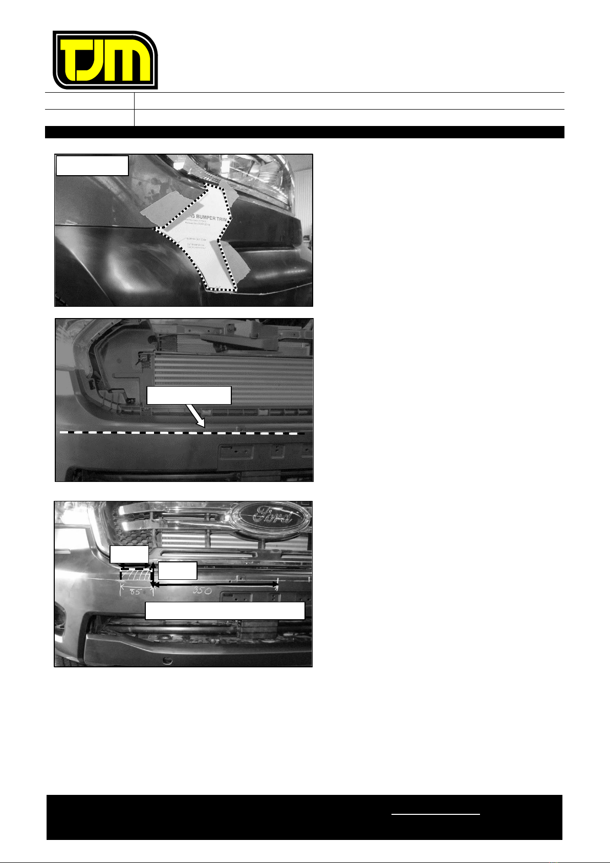
1. Remove and retain the number plate.
2. Cut out templates and attach to bumper.
3. Remove & retain the number-plate, discarding
the fastener.
4. Using the top of the number plate holes as
reference, mark a horizontal cut line along the
bumper. 10mm down frome the feature edge.
4.1. Trim the bumper along the trim line
marked.
5. 350mm from the bumper centreline, mark a
rectangle 85mm wide by 35mm high, as
shown. Repeat both sides
RHS SHOWN
FEATURE EDGE
350 mm OUT FROM CENTRE LINE
35 mm
85 mm
FITTING INSTRUCTIONS
Product:
T13 Outback Frontal Protection System
Vehicle:
Ford Ranger PXIII
Part No.
070SB13N21W
For product warranty please refer to our website www.tjm.com.au
F-27198.docx
Page 5 of 27
04/11/2021
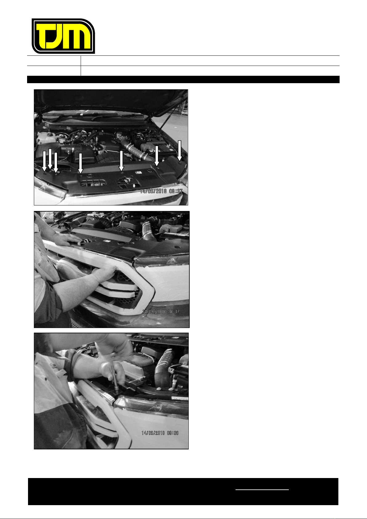
6. Remove and retain the 5 clips securing the
grille/radiator apron, in addition to the 2 bolts
securing the air intake.
7. Releasing the grille/radiator apron clips from
behind the grille (as shown), remove and
retain the grille/radiator apron.
8. Remove and retain the 2 bolts securing the
top of the grille to the vehicle (as shown)

FITTING INSTRUCTIONS
Product:
T13 Outback Frontal Protection System
Vehicle:
Ford Ranger PXIII
Part No.
070SB13N21W
For product warranty please refer to our website www.tjm.com.au
F-27198.docx
Page 6 of 27
04/11/2021
9. From behind the grille, remove and retain the
hex head bolts (2) securing the lower portion
of both sides of the grille to the vehicle.
10. From both sides of the vehicle, remove and
discard the plastic clips and screws that secure
the lower bumper (& skirting) in place.
11. Remove and discard the lower bumper
skirting.
12. On both sides of the vehicle, release the
plastic inner guard from the bumper,
discarding all of the fasteners.
13. Remove bumper to fender screw both sides
and retain.
14. Disconnect any wiring harnesses secured to
the bumper.
15. Carefully remove the bumper.
RHS SHOWN
SKIRTING
RHS SHOWN
RHS SHOWN
RHS SHOWN

FITTING INSTRUCTIONS
Product:
T13 Outback Frontal Protection System
Vehicle:
Ford Ranger PXIII
Part No.
070SB13N21W
For product warranty please refer to our website www.tjm.com.au
F-27198.docx
Page 7 of 27
04/11/2021
16. Remove and retain the OE front underbody
guard and associated fasteners.
17. Remove center lower bumper support brackets
at lower air dam position.
18. Remove the bumper and grille assembly from
the vehicle.
19. Remove and discard the clips (2) securing the
foam to the intrusion beam.
20. Remove and discard foam.
IF THE VEHICLE IS EQUIPPED WITH
RADAR, FOLLOW THE BELOW STEPS
TO REMOVE IT
USE EXTREME CAUTION IN HANDLING
THE RADAR. DAMAGE CAUSED BY
MISHANDLING IS NOT
WARRANTABLE!
21. Unplug harness from the rear of the radar
22. Remove and discard the fasteners (3) securing
the radar bracket to the intrusion beam.
Carefully set aside radar.

FITTING INSTRUCTIONS
Product:
T13 Outback Frontal Protection System
Vehicle:
Ford Ranger PXIII
Part No.
070SB13N21W
For product warranty please refer to our website www.tjm.com.au
F-27198.docx
Page 8 of 27
04/11/2021
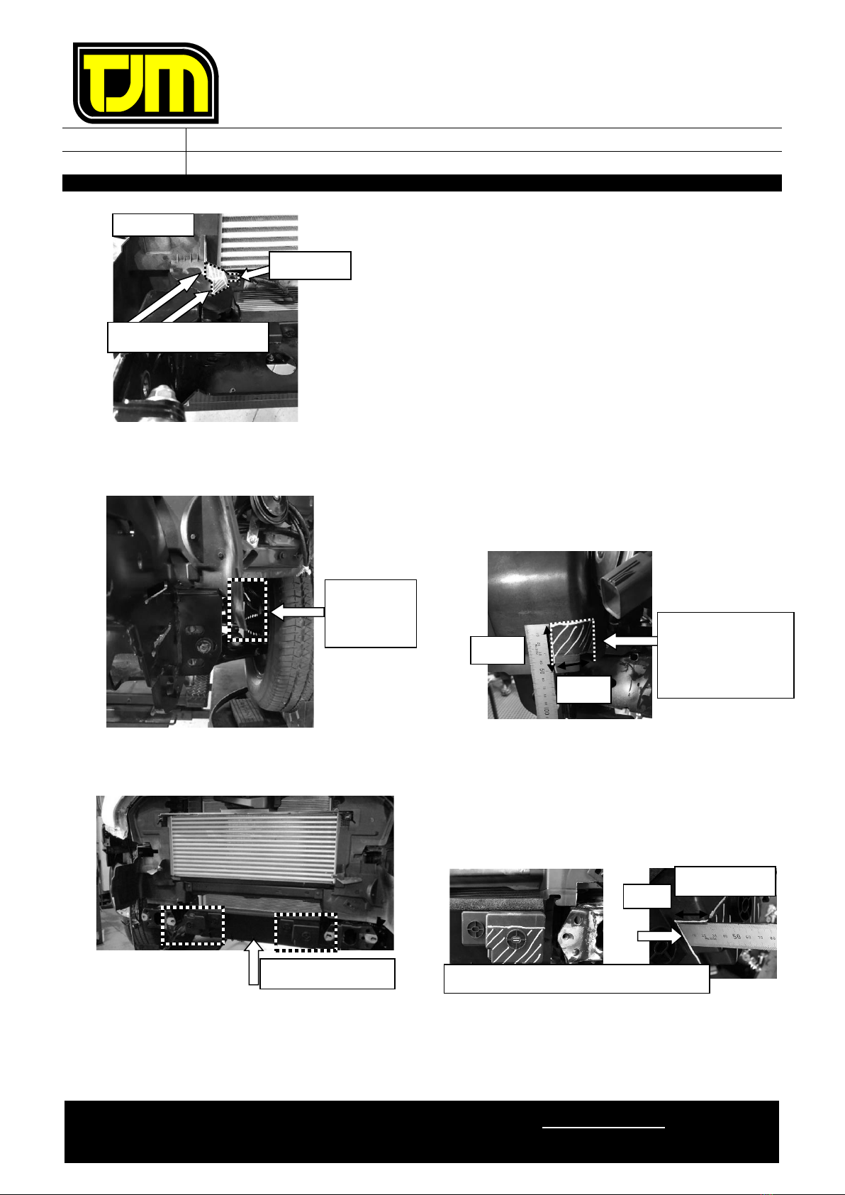
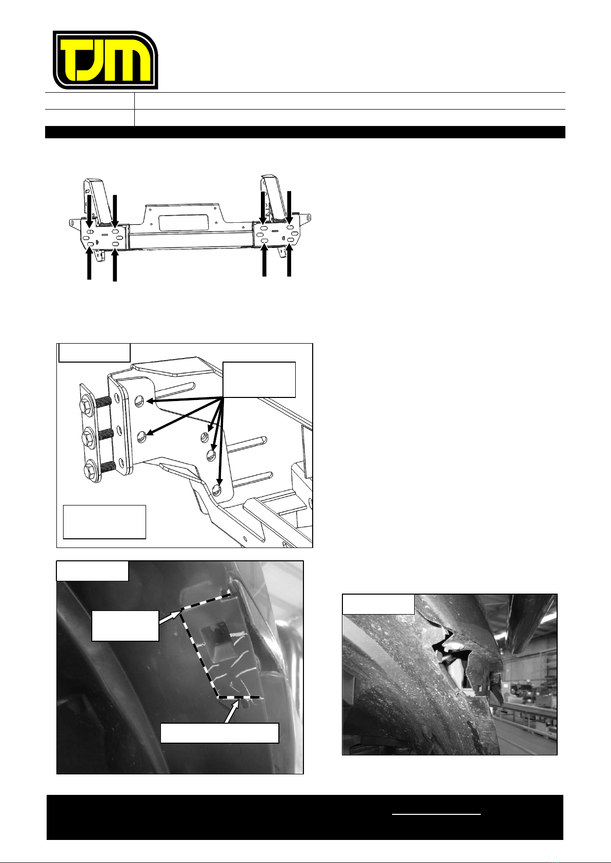
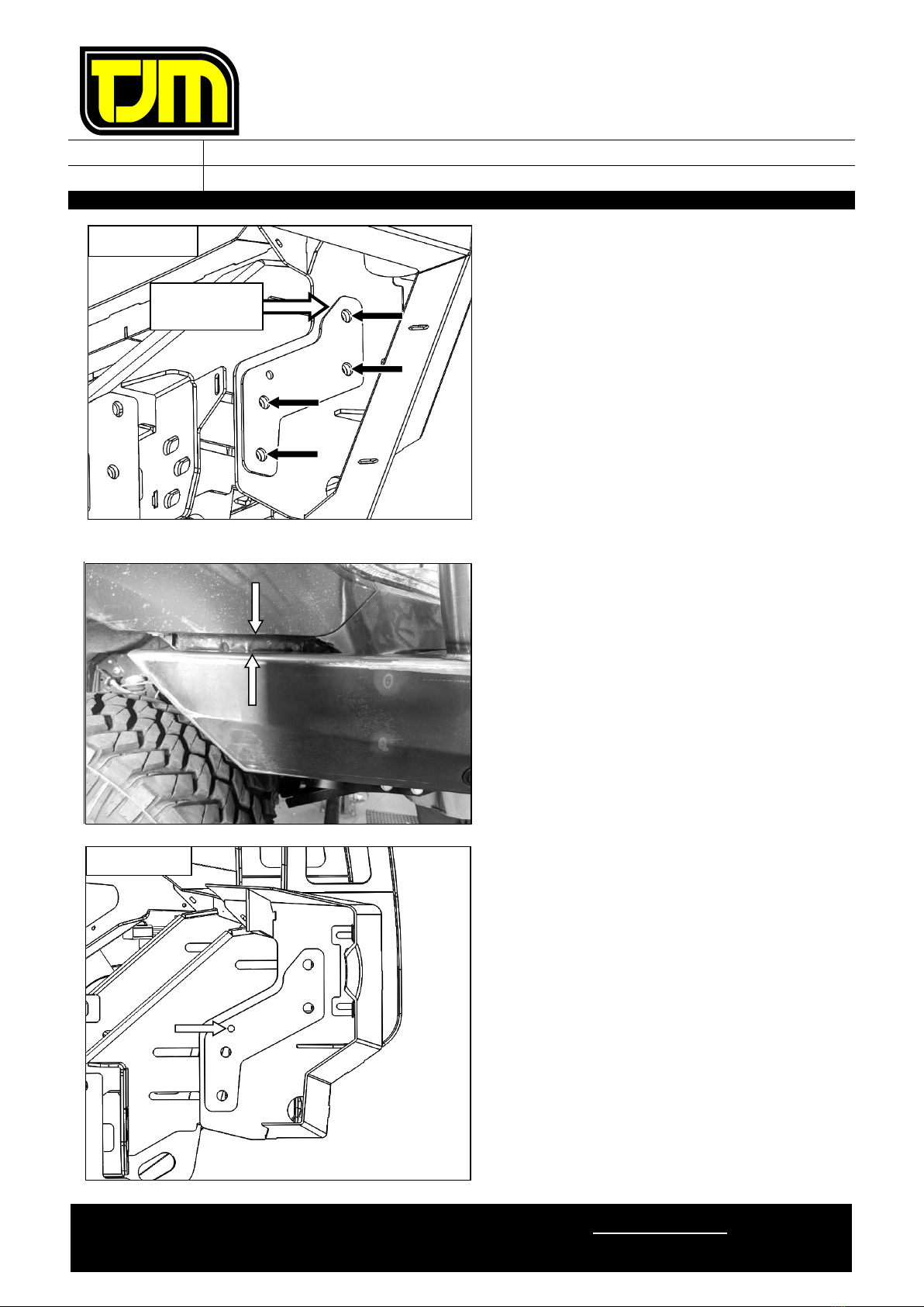
23. Remove and discard the front intrusion beam
following the below steps:
23.1. Remove and discard the clips on the
lower plastic air guides.
23.2. Remove and retain the front intrusion
beam fasteners (4) from the indicated
locations.
24. Mark the air guide as per following process.
24.1. Mark a line on as per contour shown
below.
24.2. Trim rubber portion and plastic
accordingly.
25. Mark the left hand air guide and cut
CAUTION: REMOVE TEMPERATURE
SENSOR ON LHS PRIOR TO CUTTING,
THEN REPLACE.
25.1. Mark the coutour line on with the same
dimension to the RHS.
25.2. Caution not to cut temperature sensor
hole.
STEP 23.2
STEP 23.2
STEP 23.2
STEP 23.2
STEP 24
STEP 26
STEP 42 RHS SHOWN
45mm
80mm
40mm
STEP 25
LHS SHOWN
STEP 25.1
Temperature sensor hole
FITTING INSTRUCTIONS
Product:
T13 Outback Frontal Protection System
Vehicle:
Ford Ranger PXIII
Part No.
070SB13N21W
For product warranty please refer to our website www.tjm.com.au
F-27198.docx
Page 9 of 27
04/11/2021
26. Trim air guide rib for winch installation only
26.1. Align cut line to corner and mark the
line as per opposite photo.
Only required to cut RHS side for clearance to
winch control box.
27. Cut the side of the air guide to allow clearance
to winch frame bracket (side view looking
from the arrow)
28. Trim lower air deflector to allow clearance to
winch frame
28.1. Mark the contour of the cut line below
28.2. Trim the part, repeat on the RHS side.
RHS SHOWN
STEP 26.1
Follow the corner profile
50 mm
30 mm
Extend the cut line
horizontally and
vertically to meet
the open edge.
Side view
Show
opposite
Lower Air deflector
Mark the horizontal line along the front face
Extend the line
30mm

FITTING INSTRUCTIONS
Product:
T13 Outback Frontal Protection System
Vehicle:
Ford Ranger PXIII
Part No.
070SB13N21W
For product warranty please refer to our website www.tjm.com.au
F-27198.docx
Page 10 of 27
04/11/2021
29. Drill a 6mm hole through the bumper support
plastics and vehicle body in the location
shown.
30. Remove the outer bumper support plastics
from the front guards.
31. Deburr and treat the new holes in the vehicle
body with a rust preventative.
Repeat on RHS.
32. Trim bumper support as shown, de-burr and
clean edges then refit to guard.
Repeat on LHS.
33.
Loosely
secure the bumper support plastics to
the vehicle body through the previously drilled
hole using an M6 x 1.0 x 30mm bolt (1), M6 x
Ø18mm washers (2) and M6 Nyloc nut (1).
Repeat on LHS.
Fit the indicator/park light wiring harness to the vehicle loom as per instructions.
Temporarily plug in supplied indicator / park light.
Check the operation then disconnect the light assemblies.
DRILL 6mm
HOLE
LHS SHOWN
RHS SHOWN
ALIGN CUT LINE
TO CORNER
RHS SHOWN

FITTING INSTRUCTIONS
Product:
T13 Outback Frontal Protection System
Vehicle:
Ford Ranger PXIII
Part No.
070SB13N21W
For product warranty please refer to our website www.tjm.com.au
F-27198.docx
Page 11 of 27
04/11/2021
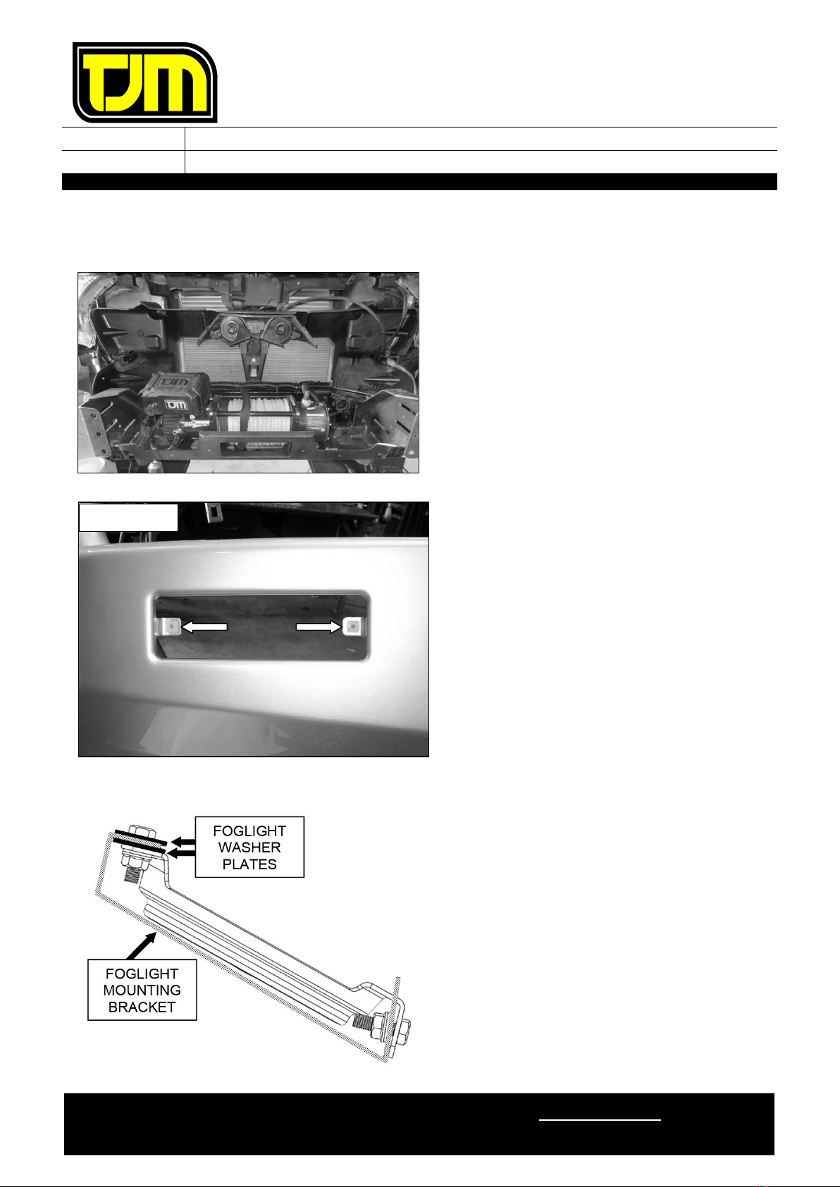
34. On both sides of the vehicle, feed the wiring
loom through the gap below the headlights.
35. Remove & discard the inner guard lower
bumper mount. Retain fasteners.
36. Unclip the wire harness body clip from the
vehicle.
37. Loosen the bolt securing the FM box and
rotate it towards the center of the car.
Retighten bolt.
38.
LHS SHOWN
RHS SHOWN
Loosen
Rotate
FITTING INSTRUCTIONS
Product:
T13 Outback Frontal Protection System
Vehicle:
Ford Ranger PXIII
Part No.
070SB13N21W
For product warranty please refer to our website www.tjm.com.au
F-27198.docx
Page 12 of 27
04/11/2021
STEPS 39 TO 43 RHS ONLY
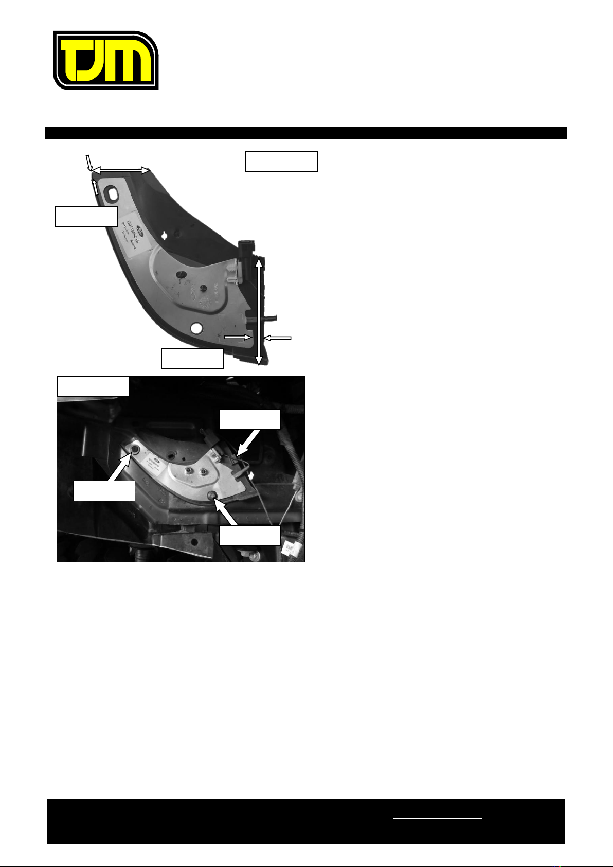
39. Mark and trim area around aerial:
39.1. Measure 5 mm up from aerial top edge
60 mm in from outside edge.
39.2. Measure 5 mm out from aerial side edge
and 100 mm up from bottom edge.
39.3. Join the two marked lines and trim
40. Deburr all edges.
41. Using a supplied M6 x Ø18mm flat washer (1)
and Christmas tree plug, secure the upper
corner of the aerial to the vehicle body as
shown.
42. Move wiring clip from radiator support panel
to the edge of the antenna where shown,
connect aerial
43. Insert the supplied grommet through the
antenna hole at the location shown. Secure to
the vehicle with an OE fastener retained from
step 35.
44. Trim the bumper along the previously marked
trim-lines.
45. Refit bumper to vehicle, using OE fasteners
retained.
46. Tighten the fasteners installed in step 33.
RHS ONLY
STEP 39.2
STEP 39.1
60mm
5mm
15mm
100mm
STEP 42
STEP 41
42
RHS ONLY
STEP 43

FITTING INSTRUCTIONS
Product:
T13 Outback Frontal Protection System
Vehicle:
Ford Ranger PXIII
Part No.
070SB13N21W
For product warranty please refer to our website www.tjm.com.au
F-27198.docx
Page 13 of 27
04/11/2021
47. With the nuts towards the center of the
vehicle, insert the inner chassis nut-plate into
the large opening in the front of the chassis
rail, ensuring the thin “leg” is positioned
towards the rear of the vehicle & touching the
bottom inside face of the chassis rail.
48. Align the holes in the inner chassis nut-plate
with the holes in the chassis rail.
49. Position the outer chassis support on the outer
face of the chassis rail (as shown), aligning
the respective holes with the inner chassis
nut-plate, then loosely secure it in place, using
M12 x 1.25 x 40mm hex screws (3), M12
spring washers (3) and 1/2” x Ø1-1/4” flat
washers (3).
50. Repeat steps 47 to 49 for the opposite side of
the vehicle.
51. Position the chassis mount / winch frame and
winch frame washer plate on the vehicle
chassis rail ends then loosely secure it in place
using the fasteners retained in step 23.2.
THE CHASSIS MOUNT / WINCH FRAME
SHOULD FIT AROUND THE PREVIOUSLY
TRIMMED AIR GUIDES.
RHS SHOWN
THESE TWO
HOLES ALIGN
RHS SHOWN
WASHER PLATE
CHASSIS RAIL END
RHS SHOWN

FITTING INSTRUCTIONS
Product:
T13 Outback Frontal Protection System
Vehicle:
Ford Ranger PXIII
Part No.
070SB13N21W
For product warranty please refer to our website www.tjm.com.au
F-27198.docx
Page 14 of 27
04/11/2021
52. Centralize the chassis mount / winch frame to
the vehicle by measuring diagonally from
mount tip to headlamp corner as shown,
equalize sizes as close as practical.
53. Tension the fasteners from step 51 to the
relevant torque settings listed on page 2.
54. Using spacers (4mm) and (2mm) supplied,
align faces between chassis, chassis mount
and chassis support bracket, assemble loosely.
54.1. Using M12 x 1.25 x 90mm hex bolts (1),
M12 nyloc nuts (1) & 1/2” x Ø1-1/4” flat
washers (2) fasten loosely in place.
54.2. Using M12 x 1.25 x 50mm hex bolts (2),
M12 nyloc nuts (2) & 1/2” x Ø1-1/4” flat
washers (4) fasten loosely in place.
REPEAT ON LHS.
If necessary, use any combination of
the supplied 2mm shims on the
relevant side (or sides) of the chassis
mount to assist in centering the
chassis mount / winch frame to the
vehicle.
=
=
RHS SHOWN
SPACERS
STEP 54.2
STEP 54.1
FITTING INSTRUCTIONS
Product:
T13 Outback Frontal Protection System
Vehicle:
Ford Ranger PXIII
Part No.
070SB13N21W
For product warranty please refer to our website www.tjm.com.au
F-27198.docx
Page 15 of 27
04/11/2021
55. Secure chassis mount / winch frame to the
vehicle through the holes shown using M10 x
1.25 x 30mm hex screws (8), M10 x Ø30mm
flat washers (16) & M10 nyloc nuts (8)
56. Tighten all fasteners installed in steps 54 and
55 to the relevant torque settings listed on
Page 2.
57. Fit clamp Angle bracket to inboard face of
winch frame and washer plate to front using
M12 x 1.25 x 35mm bolts (3), 1/2”x Ø1-1/4”
Flat Washers (6) & M12 nyloc nuts (3).
IMPORTANT –FIT M12 BOLT ASSEMBLY
WITH BOLT HEAD ON FRONT FACE.
58. Align plate with existing holes and tighten to
specified torque. Check holes and slots align
after tightening to allow easy bolt
fitment/clearance.
REPEAT ON LHS.
59. Mark and trim clearance relief cut on inner
guard aligning to features shown.
NUTS
TO INSIDE!
RHS SHOWN
Holes must
align
RHS SHOWN
AS TRIMMED
ALONG TOP OF SLOT
ALONG
EDGE
FITTING INSTRUCTIONS
Product:
T13 Outback Frontal Protection System
Vehicle:
Ford Ranger PXIII
Part No.
070SB13N21W
For product warranty please refer to our website www.tjm.com.au
F-27198.docx
Page 16 of 27
04/11/2021
Steps 60 to 61 only apply if a winch is to be fitted.
Otherwise please proceed to step 62.
60. Refer to the winch fitting instructions to fit the
winch to the chassis mount / winch frame.
61. Further trim the bumper as necessary to
accommodate winch control box.
DO NOT INSTALL WINCH FASTENERS AT
THIS TIME.
62. Insert the nylon plugs supplied, into the
square cut-outs for the indicator / park light
(as shown).
63. Separate the indicator / park light body from
the backing plate.
64. Secure the backing plate to the FPS, using the
screws provided with the light assemblies.
65. Supporting the backing plate, refit (clip) each
indicator / park light body ensuring that an
adequate seal is achieved.
Ensure that the park light is towards
the outside of the vehicle.
66. Repeat steps 62 to 65 for the opposite side of
the vehicle.
If an optional fog light kit has been
purchased, install it now, referring to the
fitting instructions provided with the kit.
Otherwise, follow the below steps to install
the provided fog light blanking covers.
67. Sandwich the fog light mounting bracket
between the fog light washer plates.
68. Position the fog light blanking cover as shown
opposite.
RHS SHOWN
FITTING INSTRUCTIONS
Product:
T13 Outback Frontal Protection System
Vehicle:
Ford Ranger PXIII
Part No.
070SB13N21W
For product warranty please refer to our website www.tjm.com.au
F-27198.docx
Page 17 of 27
04/11/2021
69. Using M6 x 1.0 x 20mm hex head screws (4),
M6 x Ø12.5mm flat washers (4) and M6 x 1.0
flange nuts (4), secure the fog light blanking
cover to the fog light mounting bracket
70. Repeat the previous three steps for the
opposite side of the vehicle.
IF NO FRONT PARKING SENSORS ARE
FITTED TO THE VEHICLE, PROCEED TO STEP
77.
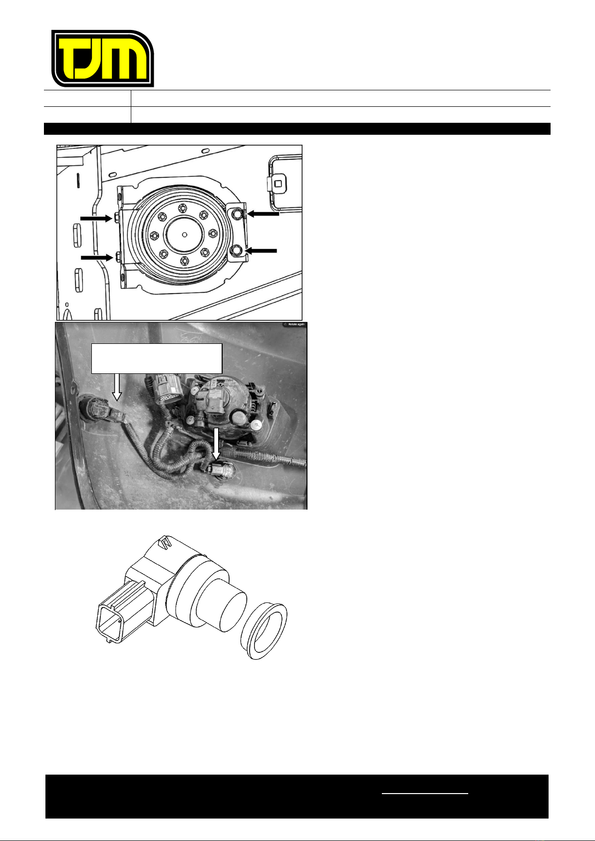
71. Looking at the lower bumper section from the
rear, record each parking sensor’s position and
orientation.
72. Remove the parking sensors and the
associated wiring harness from the bumper.
73. Feed the parking sensor loom through the FPS
channel, securing with cable ties.
IF PARKING SENSORS ARE NOT FITTED TO
THE VEHICLE, PROCEED TO STEP 77.
IF ONLY 4 PARKING SENSORS ARE FITTED
TO THE FRONT OF THE VEHICLE, PROCEED
TO STEP 75.
74. For the 2 outermost (longer) parking sensors,
install an isolating ring (supplied in the fitting
kit) over the top of the factory installed clear
rubber, with the flanged end towards the
painted surface of the parking sensor.
COMPLETE ALL REMAINING STEPS AS PER
A 4 PARKING SENSOR SYSTEM
RECORD ORIENTATION
OF CONNECTORS
FITTING INSTRUCTIONS
Product:
T13 Outback Frontal Protection System
Vehicle:
Ford Ranger PXIII
Part No.
070SB13N21W
For product warranty please refer to our website www.tjm.com.au
F-27198.docx
Page 18 of 27
04/11/2021
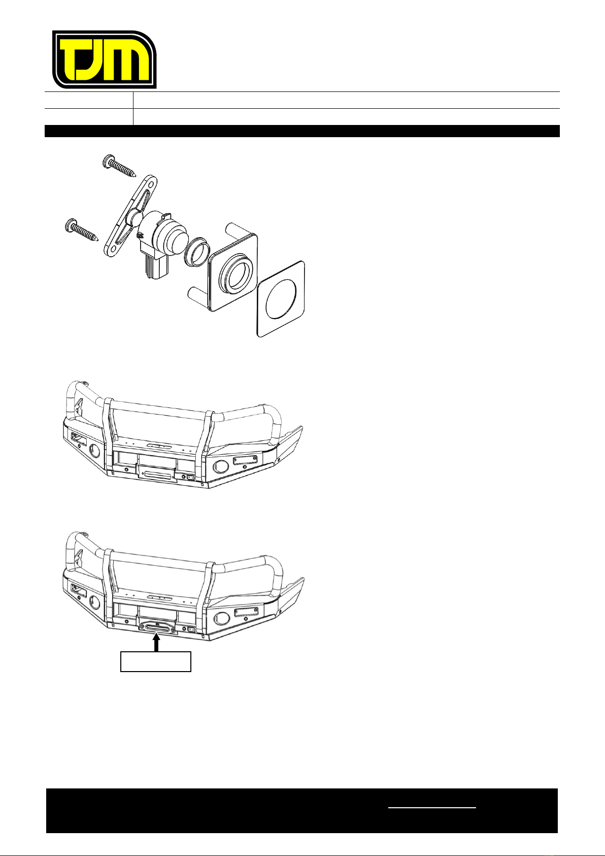
75. Remove the OE rubber isolating ring from the
parking sensors and replace with the isolating
rings supplied in the fitting kit.
76. Press out the blanking from the front of the
parking sensor housing and insert the parking
sensor.
77. Secure the parking sensor retaining plate to
the parking sensor housing using the supplied
8g x 25mm pan head screws.
78. Apply the supplied 1.2mm (thicker) double
sided sticker to the front face of the parking
sensor housing.
79. Clean mountings surfaces so they are free of
oils & residues, then affix the parking sensor
housings to the rear side of the FPS.
IF PARKING SENSORS ARE FITTED, ENSURE
THEY ARE POSITIONED AND ORIENTED
ACCORDING TO THE NOTES MADE IN STEP
71 AND CONNECT TO THE SENSOR LOOM.
STEP 80 ONLY APPLIES IF A WINCH IS
FITTED.
80. Install the fairlead supplied with the winch to
the front of the FPS as shown.
PROCEED TO STEP 85
FAIRLEAD

FITTING INSTRUCTIONS
Product:
T13 Outback Frontal Protection System
Vehicle:
Ford Ranger PXIII
Part No.
070SB13N21W
For product warranty please refer to our website www.tjm.com.au
F-27198.docx
Page 19 of 27
04/11/2021
81. Position the fairlead opening cover as shown &
secure it in place, using M10 x 1.5 x 20mm
Button head bolts (2), M10 x Ø20mm Flat
Washers (4) and M10 x 1.5 Nyloc nuts (2).
82. Fit the LH & RH grilles using hinge bush (item
18) (4), M5 x 0.8 x 20mm pan head screw (4),
M5 x Ø10mm flat washers (4) & M5 nyloc nut
(4).
M5 x Ø10mm flat washers to be used on
nyloc nut side only.
83. Fit the spring latch to the FPS as shown, using
a M6 x 1 x 20mm S/S Button head bolt, M6 x
Ø12.5mm S/S Flat washers (2) & M6 S/S
Nyloc Nut.
84. Adjust as required to reduce play in the grill
and allow easy unlatching.
Repeat on opposite side.
FAIRLEAD COVER
FITTING INSTRUCTIONS
Product:
T13 Outback Frontal Protection System
Vehicle:
Ford Ranger PXIII
Part No.
070SB13N21W
For product warranty please refer to our website www.tjm.com.au
F-27198.docx
Page 20 of 27
04/11/2021
85. With the assistance of another person,
carefully lift the FPS into position on the
chassis mount, then loosely secure it in place,
using supplied “ Sliding washer plate” and
M12 x 1.25 x 40mm hex bolts (4), 1/2" x Ø1-
1/4" flat washers (8) & M12 nyloc nuts (4) at
the indicated locations.
IMPORTANT: SLIDING WASHER PLATE
MUST BE ORIENTATED CORRECTLY AS
SHOWN!
REPEAT ON LHS.
86. Align the FPS to the vehicle so that the guard
clearance is 20 to 25mm, and wing is aligned
with wheel arch.
87. Tighten all of the fasteners to the relevant
torque settings listed on Page 2.
88. Re-connect the indicator / park lights to the
corresponding wiring harness.
89. Check the operation of the indicators, park
lights, and any fog lights, winches, etc to
ensure that they are functioning correctly.
90. Use the indicated hole in the sliding washer
plate as a guide and drill an Ø8mm hole
through the mounts in both sides of the
vehicle. Keep the drill square to align with
holes in winch frame.
91. De-burr all new edges, clean any swarf from
the areas and apply rust preventative to
exposed surfaces.
92. Secure through the holes drilled in step 90
using M8 x 1.25 x 35mm hex screws (2), M8
x Ø24 flat washers (4) & M8 x 1.25 nyloc
nuts (2).
93. Tension the fasteners to the specified torque
settings listed on page 1.
RHS SHOWN
CHAMFER
TO TOP
RHS SHOWN
Other manuals for T13
8
Other TJM Automobile Accessories manuals


Popular Automobile Accessories manuals by other brands


ULTIMATE SPEED
ULTIMATE SPEED 279746 Assembly and Safety Advice

SSV Works
SSV Works DF-F65 manual

ULTIMATE SPEED
ULTIMATE SPEED CARBON Assembly and Safety Advice

Witter
Witter F174 Fitting instructions

WeatherTech
WeatherTech No-Drill installation instructions

TAUBENREUTHER
TAUBENREUTHER 1-336050 Installation instruction