TJM 070SB13N20A User manual

FITTING INSTRUCTIONS
Product:
T13 Outback Frontal Protection System
Vehicle:
Ford Ranger PXII, PXIII (Non-Tech pack), Everest (UA model only)
Part No.
070SB13N20A
For product warranty please refer to our website www.tjm.com.au
F-12114
Page 1 of 27
03/01/2019
Australian Standards Relating to Installing Vehicle Frontal Protection Systems (VFPS): AS 4876.1-2002
a) Do not attach V.F.P.S. to vehicle using anchorages not intended for this purpose (e.g. engine mounting bolts), other than those
specified by the V.F.P.S. manufacturer in this instruction.
b) Do not use this product for any vehicle make or model other than those specified by the V.F.P.S. manufacturer (as above).
c) Do not remove any plaques or labels from the V.F.P.S.
d) Do not modify the structure of the V.F.P.S. in any way.
•Read instructions fully before commencing fitment.
•Estimated Fitting Time: 4hrs
•076SKITB20A and 946TQEXT500 supplementary kits may also be required
for vehicles fitted with a radar. (Not compatible with centrally mount radar)
•076PSHOUSE supplementary kit may be required for vehicles fitted with 6
front parking sensors.
•The fitment of TJM products does not nullify the OE manufacturer's
operating guidelines and/or warnings. Ensure you are familiar with and
adhere to the usage instructions specified by the manufacturer in the
owner's manual or other official documentation.
•Left hand and Right hand components are determined as seated in the
vehicle.
•Check for (and remove) any build up in all captive nuts fitted to the FPS.
•Be aware that a number of government / fleet departments require that the
tow points be painted red.
•Ensure that the “Rated Recovery Point Label” is affixed alongside the
compliance label, in the driver’s side doorjamb.
•When fitting accessories to TJM products (ie. driving lights and aerials),
ensure suitable washer plates are used under the mounting surface that
allow the accessory to be secured in a way that prevents it from damaging
the product.
•When removing protective coatings, ensure all new edges are deburred,
clean any swarf from the area and apply rust preventative to exposed
surfaces.
Bolt tensions
Dia. (mm)
Nm
ft.lbs
Dia. (inch)
Nm
ft.lbs
All bolt tensions are
as follows unless
otherwise
specified.
5
5
4
1/4”
9
7
6
9
7
5/16”
22
15
8
22
16
3/8”
33
27
10
44
32
7/16”
55
43
12
77
57
1/2”
86
66

FITTING INSTRUCTIONS
Product:
T13 Outback Frontal Protection System
Vehicle:
Ford Ranger PXII, PXIII (Non-Tech pack), Everest (UA model only)
Part No.
070SB13N20A
For product warranty please refer to our website www.tjm.com.au
F-12114
Page 2 of 27
03/01/2019

FITTING INSTRUCTIONS
Product:
T13 Outback Frontal Protection System
Vehicle:
Ford Ranger PXII, PXIII (Non-Tech pack), Everest (UA model only)
Part No.
070SB13N20A
For product warranty please refer to our website www.tjm.com.au
F-12114
Page 3 of 27
03/01/2019
ITEM
NO.
Description
Qty
Part
Number
PARTS LIST
1
T13 Outback FPS
1
F-11172
2
Chassis Mount / Winch Frame
1
F-10773
3
Center Guard
1
F-10991
4
Wing Guard LH
1
F-10569L
5
Wing Guard RH
1
F-10569R
FITTING KIT
6
Chassis Brace LH
1
F-1072L
7
Chassis Brace RH
1
F-1072R
8
Inner Chassis Nut-Plate LH
1
F-1075L
9
Inner Chassis Nut-Plate RH
1
F-1075R
10
Bend Angle LH
1
F-10861L
11
Bend Angle RH
1
F-10861R
12
Bending Washer Plate
2
F-8052
13
Sliding Washer Plate
2
F-10874
14
Fairlead Cover
1
F-11350
15
Spacer 2mm
2
F-8918
16
Spacer 4mm
2
F-8921
17
LED Parker/Indicator
2
92600
18
Winch Slot Cover Insert
1
92106
19
Winch Frame Washer Plate
2
F-11003
20
Wing Guard Bracket
2
F-11004
21
Parking Sensor Housing Kit
4
F-5417
22
Fusebox Vent Bracket
1
F-9896
23
LED Fog-Light and Mount Kit
1
92675
N/A
Bumper Trim Template
1
F-11766-T
N/A
12.7mm Plastic Plug
4
K0765
N/A
Nylon Plug
4
K0665
N/A
Rated Recovery Point Label
1
HC0064
N/A
Recovery Point Use Guide
1
F-1768
N/A
Pinch-Weld (750mm Long)
1
93154
N/A
TJM LOGO Sticker
1
K3550
N/A
Rubber Grommet
1
92645
N/A
Christmas Tree Plug
1
K0666
N/A
Vent Hose (530mm)
1
K3075
N/A
Cable Tie (300mm)
8
K1148
N/A
Foam Tape (750mm)
1
K1361
ITEM
NO.
Description
Qty
Part
Number
BOLT KIT
N/A
M6 x 1.0 x 20mm Hex Head Bolt
16
K0550
N/A
M6 x 1.0 x 30mm Hex Head Bolt
2
K3220
N/A
M6 x 1.0 Flange Nut
2
K3033
N/A
M6 x 1.0 Cage Nut Type B
6
K1550
N/A
M6 x 1.0 Nyloc Nut
2
K0605
N/A
M6 Spring Washer
14
K0915
N/A
M6 x Ø12.5mm Flat Washer
8
K0897
N/A
M6 x Ø18mm x 1.6mm Flat Washer
11
K2905
N/A
M8 x 1.25 x 35mm Hex Bolt
4
K0555
N/A
M8 x Ø24mm Flat Washer
6
-
N/A
M8 Spring Washer
2
K0620
N/A
M8 x 1.25 Nyloc Nut
2
K0606
N/A
M8 Cage Nut
2
K1560
N/A
M10 x 1.25 x 20mm Hex Bolt
2
K0938
N/A
M10 x 1.25 x 30mm Hex Bolt
8
K0564
N/A
M10 x 1.25 Nyloc Nut
8
K3099
N/A
M10 x 1.25 Flange Nut
2
K3036
N/A
M10 x Ø30mm Flat Washer
16
WSST-W13
N/A
M10 x Ø20mm Flat Washer
2
-
N/A
M12 x 1.25 x 35mm Hex Bolt
6
K0570
N/A
M12 x 1.25 x 40mm Hex Head Screw
14
K0571
N/A
M12 x 1.25 x 50mm Hex Bolt
4
K0572
N/A
M12 x 1.25 x 90mm Hex Bolt
2
K0976
N/A
M12 x 1.25 Nyloc Nut
20
K1200
N/A
M12 Spring Washer
6
K0977
N/A
1/2" x Ø1-1/4” Flat Washer
46
K0623

FITTING INSTRUCTIONS
Product:
T13 Outback Frontal Protection System
Vehicle:
Ford Ranger PXII, PXIII (Non-Tech pack), Everest (UA model only)
Part No.
070SB13N20A
For product warranty please refer to our website www.tjm.com.au
F-12114
Page 4 of 27
03/01/2019
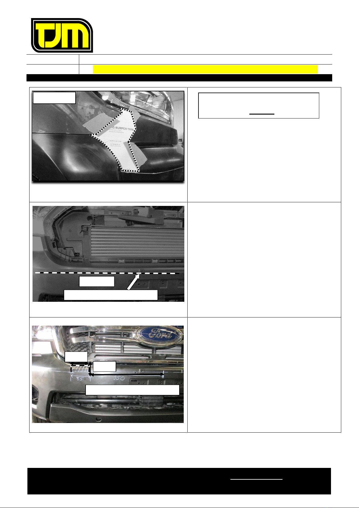
FOR PXII Bumper and Grille cut
refer steps 1-23 below:
1. Cut out templates and attach to bumper.
2. Mark trim line 10mm below feature edge.
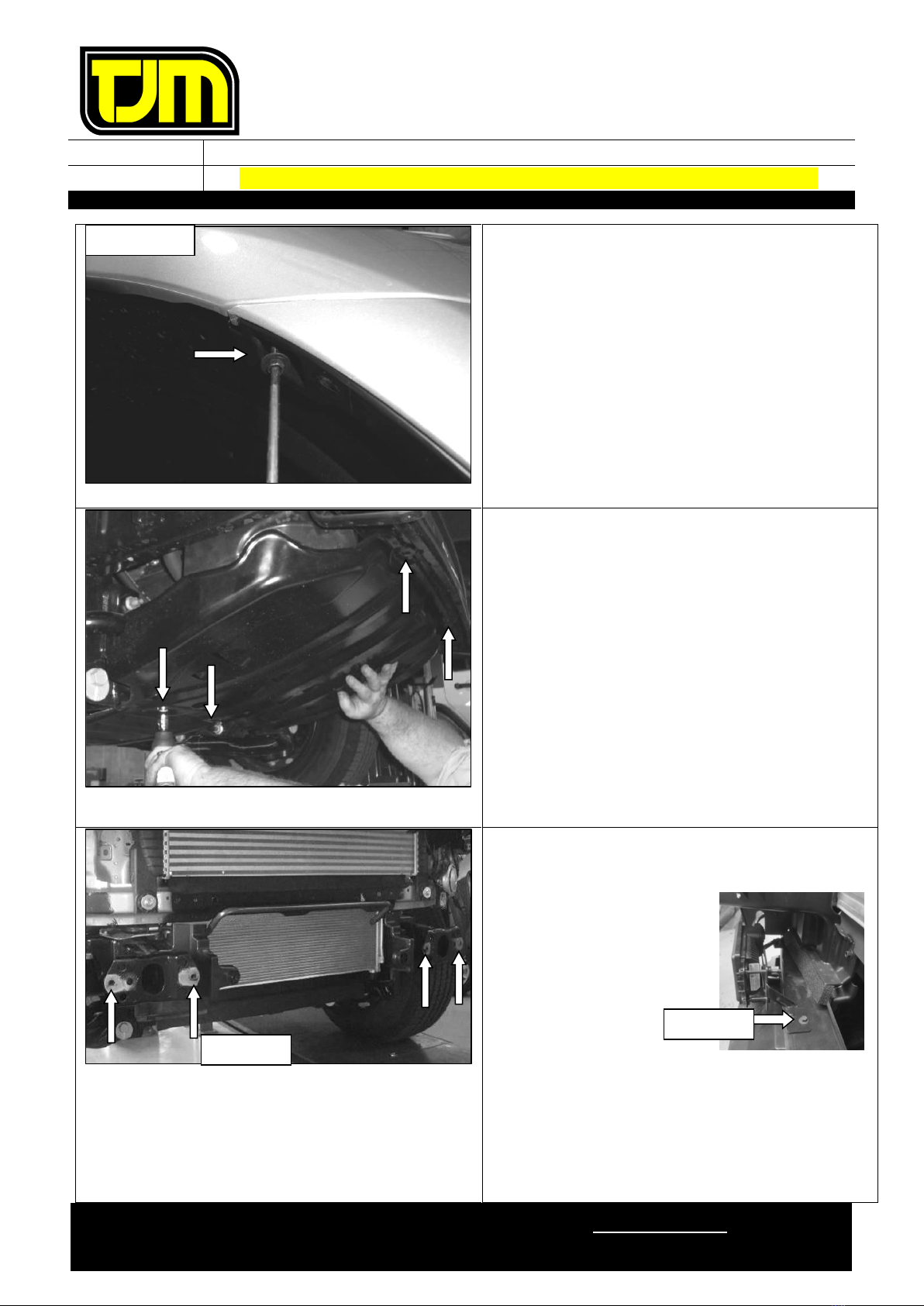
3. Remove and retain the number plate,
discarding the fasteners.
4. Remove and retain the plastic clips (5) that
secure the top of the grille/radiator shroud.
5. Raise shroud at grille, release and remove
clips underneath.
6. Inside lower grille area behind air dam, locate
and remove grille and bumper retaining
screws.
Note : Grille will need to be removed to expose
center retaining clips.
LHS SHOWN
LHS SHOWN
TEMPLATE
MARK TRIM LINE 10mm BELOW FEATURE EDGE
LOCATION
LHS SHOWN
FEATURE EDGE

FITTING INSTRUCTIONS
Product:
T13 Outback Frontal Protection System
Vehicle:
Ford Ranger PXII, PXIII (Non-Tech pack), Everest (UA model only)
Part No.
070SB13N20A
For product warranty please refer to our website www.tjm.com.au
F-12114
Page 5 of 27
03/01/2019
7. Gently disengage the clips (2) along each side
of the grille before releasing lower clips (8).
Take care as the clips which connect
the grille to the bumper are a molded
part of the grille & the clips can break
easily if proper care is not taken.
8. Remove the grille from vehicle & set it aside.
9. Remove and discard the newly exposed upper
bumper clips indicated (4).
10. From both sides of the vehicle, remove and
discard the plastic clips and screws that secure
the lower bumper (& skirting) in place.
11. Remove and discard the lower bumper
skirting.
RHS SHOWN
SKIRTING
RHS SHOWN
FITTING INSTRUCTIONS
Product:
T13 Outback Frontal Protection System
Vehicle:
Ford Ranger PXII, PXIII (Non-Tech pack), Everest (UA model only)
Part No.
070SB13N20A
For product warranty please refer to our website www.tjm.com.au
F-12114
Page 6 of 27
03/01/2019
12. On both sides of the vehicle, release the
plastic inner guard from the bumper,
discarding all of the fasteners.
13. Remove bumper to fender screw both sides
and retain.
14. Disconnect any wiring harnesses secured to
the bumper.
15. Carefully remove the bumper leaving the
templates in place for marking at step 19.
16. Remove and retain the OE front underbody
guard and associated fasteners.
17. Remove center lower bumper support brackets
at lower air dam position.
18. Remove and discard the front intrusion beam
using the following steps:
18.1. If radar is fitted,
remove and
retain mount
bracket with
radar in place for
later installation.
18.2. Remove and retain the front intrusion
beam fasteners (4) from the indicated
locations.
18.3. Remove and discard the clips on the
lower plastic air guides.
RHS SHOWN
STEP 18.1
STEP 18.2

FITTING INSTRUCTIONS
Product:
T13 Outback Frontal Protection System
Vehicle:
Ford Ranger PXII, PXIII (Non-Tech pack), Everest (UA model only)
Part No.
070SB13N20A
For product warranty please refer to our website www.tjm.com.au
F-12114
Page 7 of 27
03/01/2019
19. Mark a trim line along the grille recess as
shown. The trim line is to be marked 15mm
from the “front” edge of hole located in
recessed face on each side.
20. Trim the bumper along all trim lines marked
and those shown on templates. Deburr all new
edges.
Caution should be used with handling
grille not to damage finish.
21. Apply paper tape to grille and mark a
horizontal cut line 10mm down from the
feature edge crease.
22. Trim the grille removing lower section.
23. On both sides of the grille centerline mark
85mm wide by 40mm high cutouts, 350mm
from centerline as shown. Trim the bumber
behind the grille to match and deburr all new
edges.
HORIZONTAL CUT LINE
10mm down
TRIM LINE
ALIGNMENT HOLES
350mm OUT FROM CENTRE LINE
40mm
85mm BOTH SIDES
REAR VIEW TRIMMING
CONNECT CUT LINES AT CORNER
15mm
FITTING INSTRUCTIONS
Product:
T13 Outback Frontal Protection System
Vehicle:
Ford Ranger PXII, PXIII (Non-Tech pack), Everest (UA model only)
Part No.
070SB13N20A
For product warranty please refer to our website www.tjm.com.au
F-12114
Page 8 of 27
03/01/2019
For PXIII 2018 bumper cut
refer steps 24-27 belows.
24. Cut out templates and attach to bumper.
25. Remove & retain the number-plate, discarding
the fastener.
26. Using the top if the number plate holes as
reference, mark a horizontal cut line along the
bumper. 10mm down frome the feature edge.
26.1. Trim the bumper along the trim line
marked.
27. Trim the bumper from grille centerline mark
85mm wide by 35mm high cuts, 350mm from
centerline as shown. Repeat both sides
RHS SHOWN
350 mm OUT FROM CENTRE LINE
35 mm
85 mm
10 mm down FROM FEATURE EDGE
STEP 26.1

FITTING INSTRUCTIONS
Product:
T13 Outback Frontal Protection System
Vehicle:
Ford Ranger PXII, PXIII (Non-Tech pack), Everest (UA model only)
Part No.
070SB13N20A
For product warranty please refer to our website www.tjm.com.au
F-12114
Page 9 of 27
03/01/2019
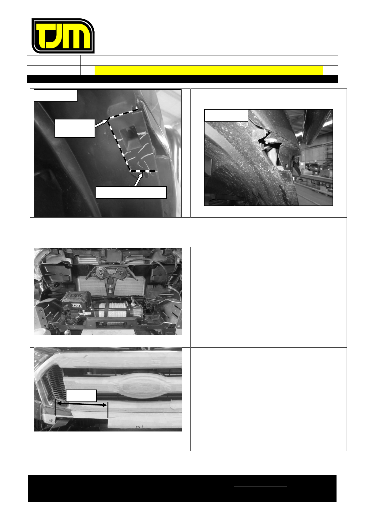
28. Drill a 6mm hole through the bumper support
plastics and vehicle body in the location
shown.
29. Remove the outer bumper support plastics
from the front guards.
30. Deburr and treat the new holes in the vehicle
body with a rust preventative.
Repeat on RHS.
31. Trim bumper support as shown, de-burr and
clean edges then refit to guard.
Repeat on LHS.
32.
Loosely
secure the bumper support plastics to
the vehicle body through the previously drilled
hole using an M6 x 1.0 x 30mm bolt (1), M6 x
Ø18mm washers (2) and M6 Nyloc nut (1).
Repeat on LHS.
DRILL 6mm
HOLE
LHS SHOWN
RHS SHOWN
ALIGN CUT LINE
TO CORNER
RHS SHOWN

FITTING INSTRUCTIONS
Product:
T13 Outback Frontal Protection System
Vehicle:
Ford Ranger PXII, PXIII (Non-Tech pack), Everest (UA model only)
Part No.
070SB13N20A
For product warranty please refer to our website www.tjm.com.au
F-12114
Page 10 of 27
03/01/2019
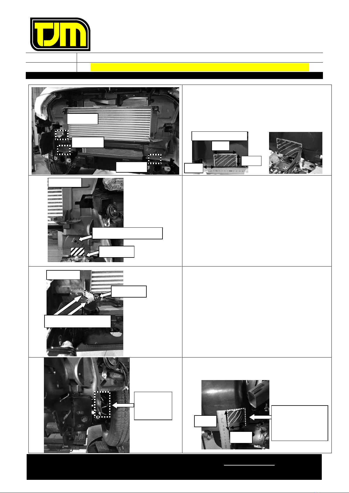
PXII Air guide cut refer steps
33-40
33. Mark the left hand lower air guide following
the below process:
33.1. Mark a horizontal line on the front face
10mm above the top of the circle
mount.
33.2. Mark a vertical line on the side face,
20mm from the flat front face.
33.3. Join the two lines previously created
with a horizontal line on the side face.
34. Repeat step 0 for the RHS then trim the lower
air guides along the marked lines.
35. Deburr the edges and clean any swarf from
the area.
36. Mark the left hand upper air guide as shown,
on the lower foam edge face.
CAUTION: REMOVE TEMPERATURE
SENSOR ON LHS PRIOR TO CUTTING,
THEN REPLACE.
37. Repeat step 36 for the RHS then trim marked
lines and deburr the edges.
LHS SHOWN
STEP 33.2
STEP 33.3
STEP 33.1
LHS SHOWN
Temperature
sensor hole
20mm
100mm
85mm
AIR GUIDE AS TRIMED
CIRCLE MOUNT

FITTING INSTRUCTIONS
Product:
T13 Outback Frontal Protection System
Vehicle:
Ford Ranger PXII, PXIII (Non-Tech pack), Everest (UA model only)
Part No.
070SB13N20A
For product warranty please refer to our website www.tjm.com.au
F-12114
Page 11 of 27
03/01/2019
38. Mark the left hand upper air guide as shown,
following the below process:
38.1. Mark a line on the top face from
mounting tab corner to a point 40mm
forward of rear edge.
38.2. Mark 2nd line from previous line down
to a point 110mm front rear edge.
38.3. On the horizontal lower face, mark a
line along the edge 95 mm from the
front.
38.4. Join the previously marked trim lines as
shown.
39. Repeat step 38 for the RHS then trim the
upper air guides to shape as shown.
40. Deburr the edges and clean any swarf from
the area.
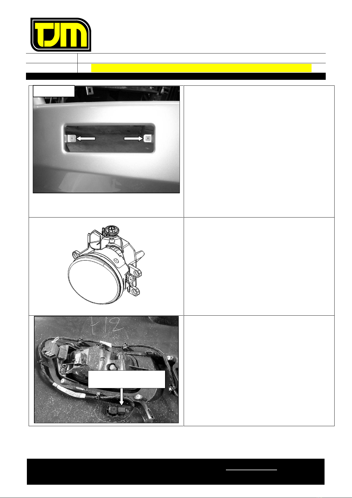
Fit the indicator/park light wiring harness to the vehicle loom as per instructions.
Temporarily plug in supplied indicator / park light and fog lights.
Check the operation then disconnect the light assemblies.
PXIII Air guide and Air deflector
cut refer steps 41-46
41. Remove the 2 clips and discard instrusion
beam foam and remove instrusion beam.
LHS SHOWN
95mm
STEP 38.4
110mm
STEP 38.1
LHS SHOWN
40mm
STEP 38.2
STEP 38.3
STEP 41
FITTING INSTRUCTIONS
Product:
T13 Outback Frontal Protection System
Vehicle:
Ford Ranger PXII, PXIII (Non-Tech pack), Everest (UA model only)
Part No.
070SB13N20A
For product warranty please refer to our website www.tjm.com.au
F-12114
Page 12 of 27
03/01/2019
42. Mark the air guide as per following process.
42.1. Mark a line on as per contour shown
below.
42.2. Trim rubber portion and plastic
accordingly.
43. Mark the left hand air guide and cut
CAUTION: REMOVE TEMPERATURE
SENSOR ON LHS PRIOR TO CUTTING,
THEN REPLACE.
43.1. Mark the coutour line on with the same
dimension to the RHS.
43.2. Caution not to cut temperature sensor
hole.
44. Trim air guide rib for winch installation only
44.1. Align cut line to corner and mark the
line as per opposite photo.
Only required to cut RHS side for clearance to
winch control box.
45. Cut the side of the air guide to allow clearance
to winch frame bracket (side view looking
from the arrow)
STEP 42
STEP 44
STEP 42 RHS SHOWN
45mm
80mm
40mm
STEP 43
LHS SHOWN
STEP 38.3
Temperature sensor hole
RHS SHOWN
STEP
38.3.1
Follow the corner profile
50 mm
30 mm
Extend the cut line
horizontally and
vertically to meet
the open edge.
Side view
Show
opposite
FITTING INSTRUCTIONS
Product:
T13 Outback Frontal Protection System
Vehicle:
Ford Ranger PXII, PXIII (Non-Tech pack), Everest (UA model only)
Part No.
070SB13N20A
For product warranty please refer to our website www.tjm.com.au
F-12114
Page 13 of 27
03/01/2019
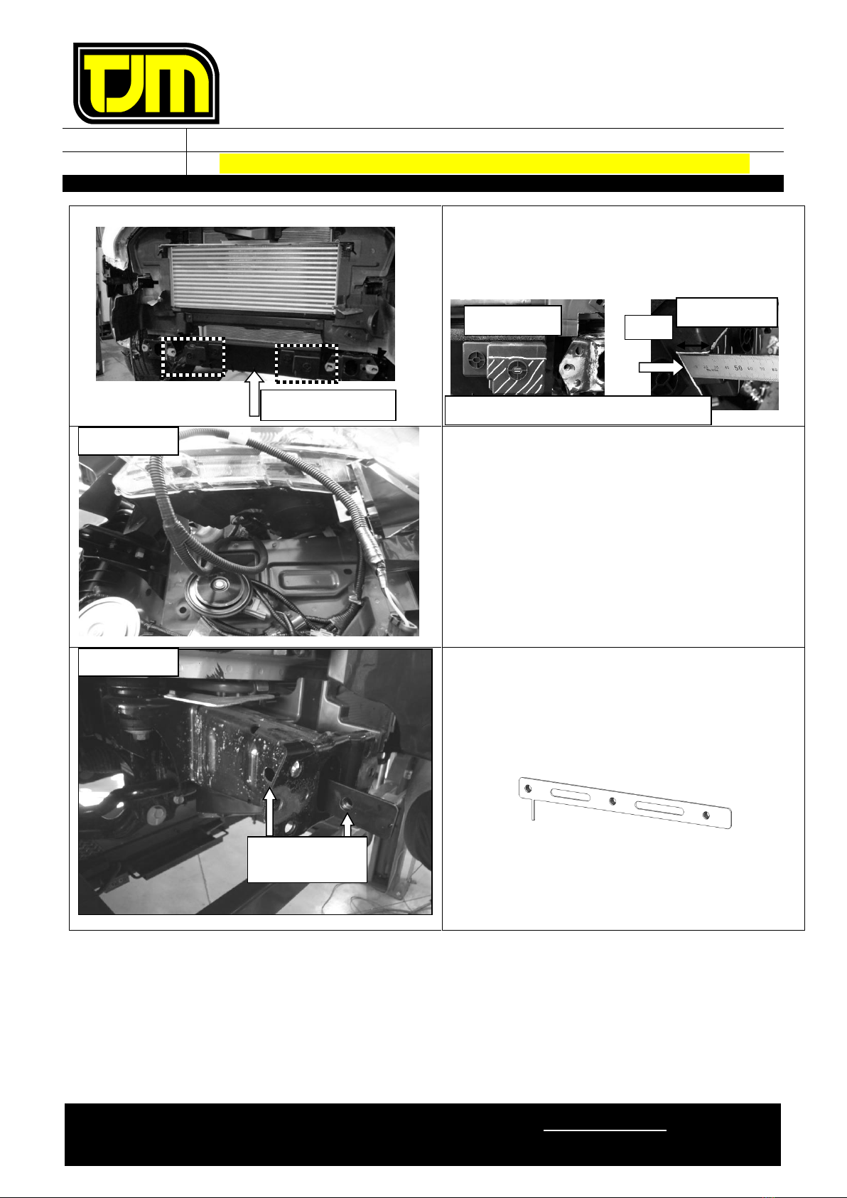
46. Trim lower air deflector to allow clearance to
winch frame
46.1. Mark the contour of the cut line below
46.2. Trim the part, repeat on the RHS side.
47. On both sides of the vehicle, feed the wiring
loom through the gap below the headlights.
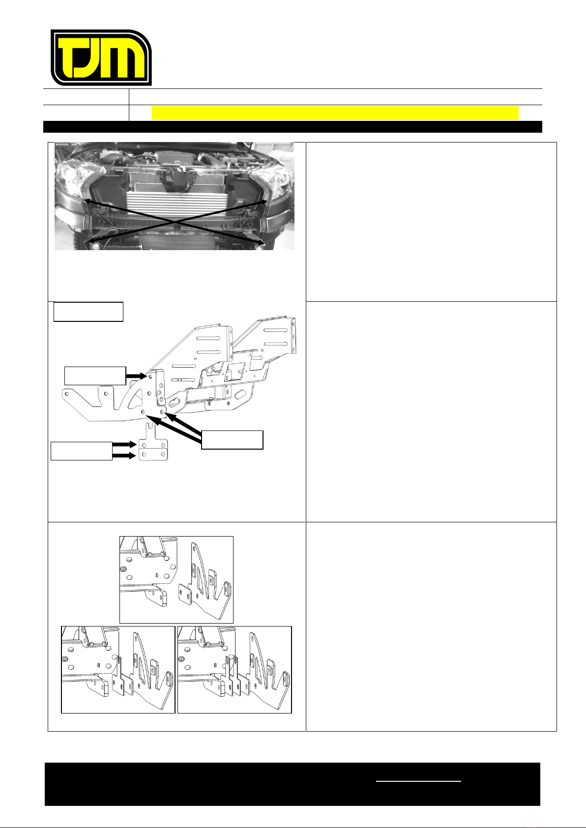
48. With the nuts towards the center of the
vehicle, insert the inner chassis nut-plate into
the large opening in the front of the chassis
rail, ensuring the thin “leg” is positioned
towards the rear of the vehicle & touching the
bottom inside face of the chassis rail.
49. Align the holes in the inner chassis nut-plate
with the holes in the chassis rail.
RHS SHOWN
THESE TWO
HOLES ALIGN
LHS SHOWN
Lower Air deflector
STEP 46.1
Mark the horizontal line along the front face
Extend the line
30mm

FITTING INSTRUCTIONS
Product:
T13 Outback Frontal Protection System
Vehicle:
Ford Ranger PXII, PXIII (Non-Tech pack), Everest (UA model only)
Part No.
070SB13N20A
For product warranty please refer to our website www.tjm.com.au
F-12114
Page 14 of 27
03/01/2019
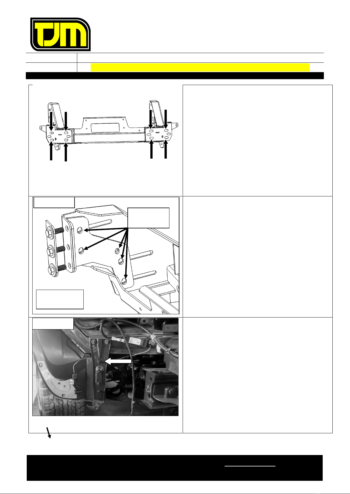
50. Position the outer chassis support on the outer
face of the chassis rail (as shown), aligning
the respective holes with the inner chassis
nut-plate, then loosely secure it in place, using
M12 x 1.25 x 40mm hex screws (3), M12
spring washers (3) and 1/2” x Ø1-1/4” flat
washers (3).
51. Repeat steps 48 to 50 for the opposite side of
the vehicle.
52. Trim a section of the air guide as shown to
provide clearance to the winch frame washer
plate
53. Position the chassis mount / winch frame and
winch frame washer plate on the vehicle
chassis rail ends then loosely secure it in place
using the fasteners retained in step 18.2.
THE CHASSIS MOUNT / WINCH FRAME
SHOULD FIT AROUND THE PREVIOUSLY
TRIMMED AIR GUIDES.
RHS SHOWN
WASHER PLATE
CHASSIS RAIL END
RHS SHOWN
FITTING INSTRUCTIONS
Product:
T13 Outback Frontal Protection System
Vehicle:
Ford Ranger PXII, PXIII (Non-Tech pack), Everest (UA model only)
Part No.
070SB13N20A
For product warranty please refer to our website www.tjm.com.au
F-12114
Page 15 of 27
03/01/2019
54. Centralize the chassis mount / winch frame to
the vehicle by measuring diagonally from
mount tip to headlamp corner as shown,
equalize sizes as close as practical.
55. Tension the fasteners from step 53 to the
relevant torque settings listed on page 2.
56. Using spacers (4mm) and (2mm) supplied,
align faces between chassis, chassis mount
and chassis support bracket, assemble loosely.
56.1. Using M12 x 1.25 x 90mm hex bolts (1),
M12 nyloc nuts (1) & 1/2” x Ø1-1/4” flat
washers (2) fasten loosely in place.
56.2. Using M12 x 1.25 x 50mm hex bolts (2),
M12 nyloc nuts (2) & 1/2” x Ø1-1/4” flat
washers (4) fasten loosely in place.
REPEAT ON LHS.
If necessary, use any combination of
the supplied 2mm shims on the
relevant side (or sides) of the chassis
mount to assist in centering the
chassis mount / winch frame to the
vehicle.
=
=
RHS SHOWN
SPACERS
STEP 56.2
STEP 56.1
FITTING INSTRUCTIONS
Product:
T13 Outback Frontal Protection System
Vehicle:
Ford Ranger PXII, PXIII (Non-Tech pack), Everest (UA model only)
Part No.
070SB13N20A
For product warranty please refer to our website www.tjm.com.au
F-12114
Page 16 of 27
03/01/2019
57. Secure chassis mount / winch frame to the
vehicle through the holes shown using M10 x
1.25 x 30mm hex screws (8), M10 x Ø30mm
flat washers (16) & M10 nyloc nuts (8)
58. Tighten all fasteners installed in steps 56 and
57 to the relevant torque settings listed on
Page 2.
59. Fit clamp Angle bracket to inboard face of
winch frame and washer plate to front using
M12 x 1.25 x 35mm bolts (3), 1/2”x Ø1-1/4”
Flat Washers (6) & M12 nyloc nuts (3).
IMPORTANT –FIT M12 BOLT ASSEMBLY
WITH BOLT HEAD ON FRONT FACE.
60. Align plate with existing holes and tighten to
specified torque. Check holes and slots align
after tightening to allow easy bolt
fitment/clearance.
REPEAT ON LHS.
61. Remove & discard the inner guard lower
bumper mount. Retain fasteners.
NUTS
TO INSIDE!
RHS SHOWN
Holes must
align
RHS SHOWN

FITTING INSTRUCTIONS
Product:
T13 Outback Frontal Protection System
Vehicle:
Ford Ranger PXII, PXIII (Non-Tech pack), Everest (UA model only)
Part No.
070SB13N20A
For product warranty please refer to our website www.tjm.com.au
F-12114
Page 17 of 27
03/01/2019
STEPS 62 TO 66 RHS ONLY
62. Mark and trim area around aerial:
62.1. Measure 5 mm up from aerial top edge
60 mm in from outside edge.
62.2. Measure 5 mm out from aerial side edge
and 100 mm up from bottom edge.
62.3. Join the two marked lines and trim
63. Deburr all edges.
64. Using a supplied M6 x Ø18mm flat washer (1)
and Christmas tree plug, secure the upper
corner of the aerial to the vehicle body as
shown.
65. Move wiring clip from radiator support panel
to the edge of the antenna where shown,
connect aerial
66. Insert the supplied grommet through the
antenna hole at the location shown. Secure to
the vehicle with an OE fastener retained from
step 61.
RHS ONLY
STEP 62.2
STEP 62.1
60mm
5mm
15mm
100mm
STEP 65
STEP 64
65
RHS ONLY
STEP 66
FITTING INSTRUCTIONS
Product:
T13 Outback Frontal Protection System
Vehicle:
Ford Ranger PXII, PXIII (Non-Tech pack), Everest (UA model only)
Part No.
070SB13N20A
For product warranty please refer to our website www.tjm.com.au
F-12114
Page 18 of 27
03/01/2019
67. Mark and trim clearance relief cut on inner
guard aligning to features shown.
Steps 68 to 71 only apply if a winch is to be fitted.
Otherwise please proceed to step 72
68. Refer to the winch fitting instructions to fit the
winch to the chassis mount / winch frame.
DO NOT INSTALL WINCH FASTENERS AT
THIS TIME.
69. When winch is fitted, further grill trimming is
required.
69.1. On the RHS only, increase 85mm cut
made in step 23 inboard to 300mm.
300 mm
RHS SHOWN
AS TRIMMED
ALONG TOP OF SLOT
ALONG
EDGE
FITTING INSTRUCTIONS
Product:
T13 Outback Frontal Protection System
Vehicle:
Ford Ranger PXII, PXIII (Non-Tech pack), Everest (UA model only)
Part No.
070SB13N20A
For product warranty please refer to our website www.tjm.com.au
F-12114
Page 19 of 27
03/01/2019
Steps 70 to 71 only apply for vehicles
fitted with radar, otherwise proceed to
step 72.
70. If radar was removed at step 18.1 install
mount bracket from kit 076SKITB20A as per
supplied instructions.
71. Fit winch control extension kit 946TQEXT500
as per supplied instruction.
A number of positions exist for mounting the winch control extension bracket
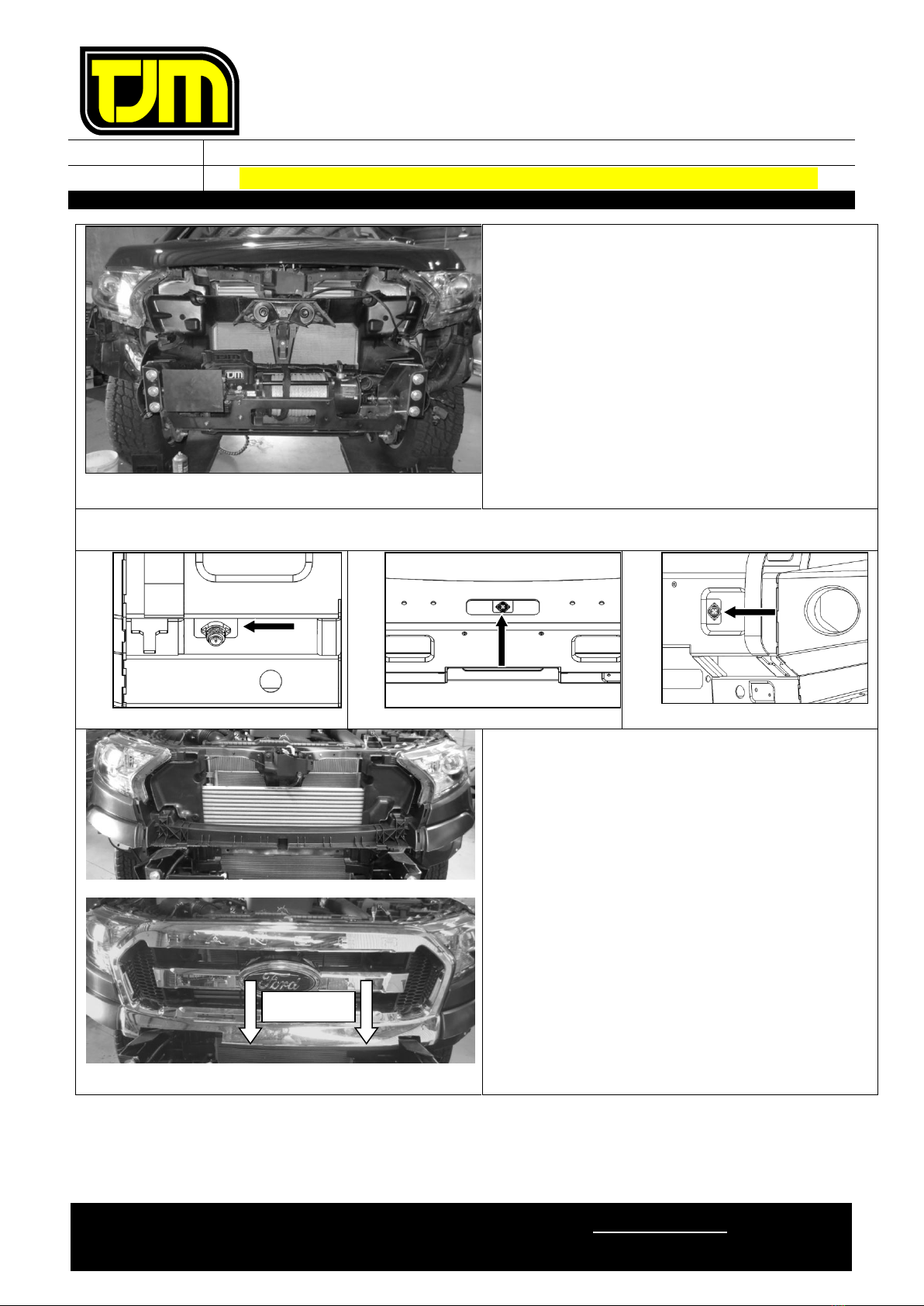
72. Refit bumper to vehicle, using OE fasteners
retained.
73. Tighten the fasteners installed in step 32.
74. Refit grille using OE fasteners retained and fit
pinch weld to lower cut edge of the outer grill
panel as shown.
STEP 74
FITTING INSTRUCTIONS
Product:
T13 Outback Frontal Protection System
Vehicle:
Ford Ranger PXII, PXIII (Non-Tech pack), Everest (UA model only)
Part No.
070SB13N20A
For product warranty please refer to our website www.tjm.com.au
F-12114
Page 20 of 27
03/01/2019
75. Insert the nylon plugs supplied, into the
square cut-outs for the indicator / park light
(as shown).
76. Separate the indicator / park light body from
the backing plate.
77. Secure the backing plate to the FPS, using the
screws provided with the light assemblies.
78. Supporting the backing plate, refit (clip) each
indicator / park light body ensuring that an
adequate seal is achieved.
Ensure that the park light is towards
the outside of the vehicle.
79. Repeat steps 75 to 78 for the opposite side of
the vehicle.
80. Refer to the fitting instructions provided in the
fog-light kit to install fog-lights to the FPS.
IF NO FRONT PARKING SENSORS ARE
FITTED TO THE VEHICLE, PROCEED TO STEP
89.
81. Looking at the lower bumper section from the
rear, record each parking sensor’s position and
orientation.
82. Remove the parking sensors and the
associated wiring harness from the bumper.
83. Feed the parking sensor loom through the FPS
channel, securing with cable ties.
RHS SHOWN
RECORD ORIENTATION
OF CONNECTOR
Table of contents
Other TJM Automobile Accessories manuals


Popular Automobile Accessories manuals by other brands


ULTIMATE SPEED
ULTIMATE SPEED 279746 Assembly and Safety Advice

SSV Works
SSV Works DF-F65 manual

ULTIMATE SPEED
ULTIMATE SPEED CARBON Assembly and Safety Advice

Witter
Witter F174 Fitting instructions

WeatherTech
WeatherTech No-Drill installation instructions

TAUBENREUTHER
TAUBENREUTHER 1-336050 Installation instruction