TJM 070SB13L32R User manual

FITTING INSTRUCTIONS
Product:
T13 Outback Deluxe Frontal Protection System
Vehicle:
Holden Colorado 2016+
Part No.
070SB13L32R
For product warranty, please refer to our website, www.tjm.com.au
File: F-13409
Page 1 of 28
28/03/2017
Australian Standards Relating to Installing Vehicle Frontal Protection Systems (VFPS): AS 4876.1-2002
a) Do not attach V.F.P.S. to vehicle using anchorages not intended for this purpose (e.g. engine mounting bolts), other than those
specified by the V.F.P.S. manufacturer in this instruction.
b) Do not use this product for any vehicle make or model other than those specified by the V.F.P.S. manufacturer (as above).
c) Do not remove any plaques or labels from the V.F.P.S.
d) Do not modify the structure of the V.F.P.S. in any way.
•Read instructions fully before commencing fitment.
•Estimated Fitting Time: 4hrs
•The fitment of TJM products does not nullify the OE manufacturer's
operating guidelines and/or warnings. Ensure you are familiar with and
adhere to the usage instructions specified by the manufacturer in the
owner's manual or other official documentation.
•Left hand and Right hand components are determined as seated in the
vehicle.
•Check for (and remove) any build up in all captive nuts fitted to the FPS.
•When fitting accessories to TJM products (ie. driving lights and aerials),
ensure suitable washer plates are used under the mounting surface that
allow the accessory to be secured in a way that prevents it from damaging
the product.
•When removing protective coatings, ensure all new edges are deburred,
clean any swarf from the area and apply rust preventative to exposed
surfaces.
•Supplementary kit 076SKITA32R is required for fitment of TJM Torq winch.
Bolt tensions
Dia. (mm)
Nm
ft.lbs
Dia. (inch)
Nm
ft.lbs
All bolt tensions are
as follows unless
otherwise
specified.
5
5
4
1/4”
9
7
6
9
7
5/16”
22
15
8
22
16
3/8”
33
27
10
44
32
7/16”
55
43
12
77
57
1/2”
86
66
FITTING INSTRUCTIONS
Product:
T13 Outback Deluxe Frontal Protection System
Vehicle:
Holden Colorado 2016+
Part No.
070SB13L32R
For product warranty, please refer to our website, www.tjm.com.au
File: F-13409
Page 2 of 28
28/03/2017

FITTING INSTRUCTIONS
Product:
T13 Outback Deluxe Frontal Protection System
Vehicle:
Holden Colorado 2016+
Part No.
070SB13L32R
For product warranty, please refer to our website, www.tjm.com.au
File: F-13409
Page 3 of 28
28/03/2017
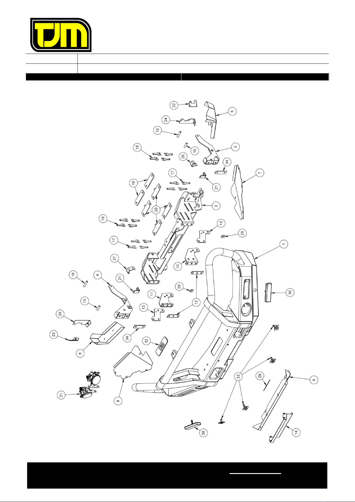
ITEM
NO.
Description
Qty
Part
Number
PARTS LIST
1
T13 Outback FPS
1
F-12439
2
Winch Frame
1
F-11945
3
Chassis Mount LH
1
F-11953L
4
Chassis Mount RH
1
F-11953R
5
Body Cover Panel LH
1
F-12830L
6
Body Cover Panel RH
1
F-12830R
7
Wing Guard LH
1
F-12831L
8
Wing Guard RH
1
F-12831R
9
Centre Guard
1
F-12796
10
Bending Angle LH
1
F-12807L
11
Bending Angle RH
1
F-12807R
12
Bending Washer Plate
2
F-12808
13
Sliding Washer Plate
2
F-12811
14
Fairlead Cover
1
F-12978
FITTING KIT
15
Spacer Tube (50mm)
2
F-13448
16
Spacer Tube (66mm)
2
F-1931
17
Chassis Spacer (2mm)
8
F-12829
18
Chassis Spacer (4mm)
8
F-13475
19
Lower Chassis Spacer (4mm)
2
F-13467
20
Lower Chassis Spacer (2mm)
4
F-13484
21
Wing Guard Bracket
2
F-12840
22
Outer Body Cover Mount LH
1
F-12879L
23
Outer Body Cover Mount RH
1
F-12879R
24
Inner Body Cover Mount LH
1
F-12878L
25
Inner Body Cover Mount RH
1
F-12878R
26
Chassis Top Bracket LH
1
F-13482L
27
Chassis Top Bracket RH
1
F-13482R
28
TJM Logo Backing Plate
1
F-13430
29
M10 Washer Plate
2
F-13798
30
LED Indicator/Parker Light
2
92600
31
LED Foglight Kit
1
92675
32
Winch Slot Cover Plate
1
92106
33
Parking Sensor Housing
4
F-5417
34
Chassis End Plate Washer
2
F-13880
N/A
Cable Tie (300mm)
8
K1148
N/A
Double Sided Tape (650mm)
1
K1361
N/A
Pinch Weld - Steel Sprung (250mm)
1
93154
N/A
Pinch Weld (600mm)
1
K3219
N/A
Bumper Trim Template
1
F-13782-T
N/A
Rated Recovery Point Label
1
HC0064
ITEM
NO.
Description
Qty
Part
Number
FACTORY FITTED
N/A
TJM Logo Sticker
1
K3550
N/A
Warning Label - ABC
1
HC0057
N/A
Rated Recovery Point Label
1
HC0064
BOLT KIT
N/A
M4 x 0.7 x 16mm Pan Head Screw
2
K0450
N/A
M4 x Ø9-12mm Flat Washer
4
K0896
N/A
M4 Nyloc Nut
2
K0894
N/A
M6 x 1.0 x 20mm Button Head Bolt
14
K3218
N/A
M6 x 1.0 x 20mm Hex Head Bolt
10
K0550
N/A
M6 x 1.0 Nyloc Nut
2
K0605
N/A
M6 x 1.0 Cage Nut
10
K1550
N/A
M6 x 1.0 Flange Nut
4
K3033
N/A
M6 Spring Washer
18
K0915
N/A
1/4" x Ø5/8” Flat Washer
26
K0626
N/A
M8 x 1.25 x 20mm Button Head Bolt
4
K1284
N/A
M8 x 1.25 x 35mm Hex Head Bolt
4
K0555
N/A
M8 Cage Nut
2
K1560
N/A
M8 x 1.25 Nyloc Nut
4
K0606
N/A
M8 Spring Washer
4
K0620
N/A
M8 x Ø19mm Flat Washer
4
K0628
N/A
5/16” x Ø1-1/4” Flat Washer
8
K0859
N/A
M10 x 1.25 x 30mm Hex Head Screw
4
K0564
N/A
M10 x 1.25 x 40mm Hex Head Bolt
8
K0566
N/A
M10 x 1.25 x 80mm Hex Head Bolt
2
K0953
N/A
M10 x 1.25 x 100mm Hex Head Bolt
2
K0962
N/A
M10 x 1.25 Nyloc Nut
8
K3099
N/A
M10 x 1.25 Flange Nut
2
K3036
N/A
M10 Spring Washer
6
K0621
N/A
M10 x Ø30mm Flat Washer
30
WSST-W13
N/A
M12 x 1.25 x 35mm Hex Head Bolt
6
K0570
N/A
M12 x 1.25 x 40mm Hex Head Bolt
8
K0571
N/A
M12 x 1.25 x 60mm Hex Head Bolt
2
K0573
N/A
M12 x 1.25 x 120mm Hex Head Bolt
2
K1955
N/A
M12 x 1.25 Nyloc Nut
18
K1200
N/A
1/2" x Ø1-1/4” Flat Washer
36
K0623
N/A
M14 x 1.5 x 45mm Hex Head Bolt
2
-
N/A
M14 x 1.5 Nyloc Nut
2
K0655
N/A
9/16” x Ø1 1/8” Flat Washer
4
K0656
N/A
Nylon Plug
4
K0665

FITTING INSTRUCTIONS
Product:
T13 Outback Deluxe Frontal Protection System
Vehicle:
Holden Colorado 2016+
Part No.
070SB13L32R
For product warranty, please refer to our website, www.tjm.com.au
File: F-13409
Page 4 of 28
28/03/2017
1.1. Mark a point at the apex of the the
bumper countour.
1.2. Draw a straight line from the point
marked in step 1.1 into the lower corner
of the spar, as shown.
1.3. Mark a bumper trim line 15mm down
from the previously marked line, as
shown.
Repeat on opposite side of vehicle.
1.4. Fit the supplied bumper cut template to
the bumper and mark the appropriate
trim lines.
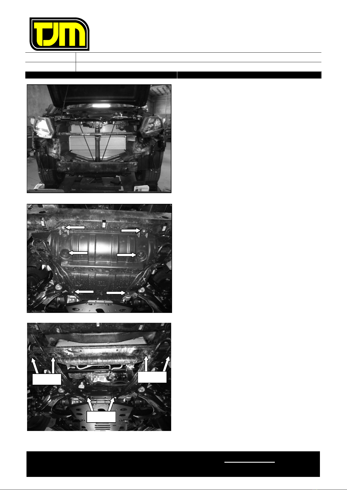
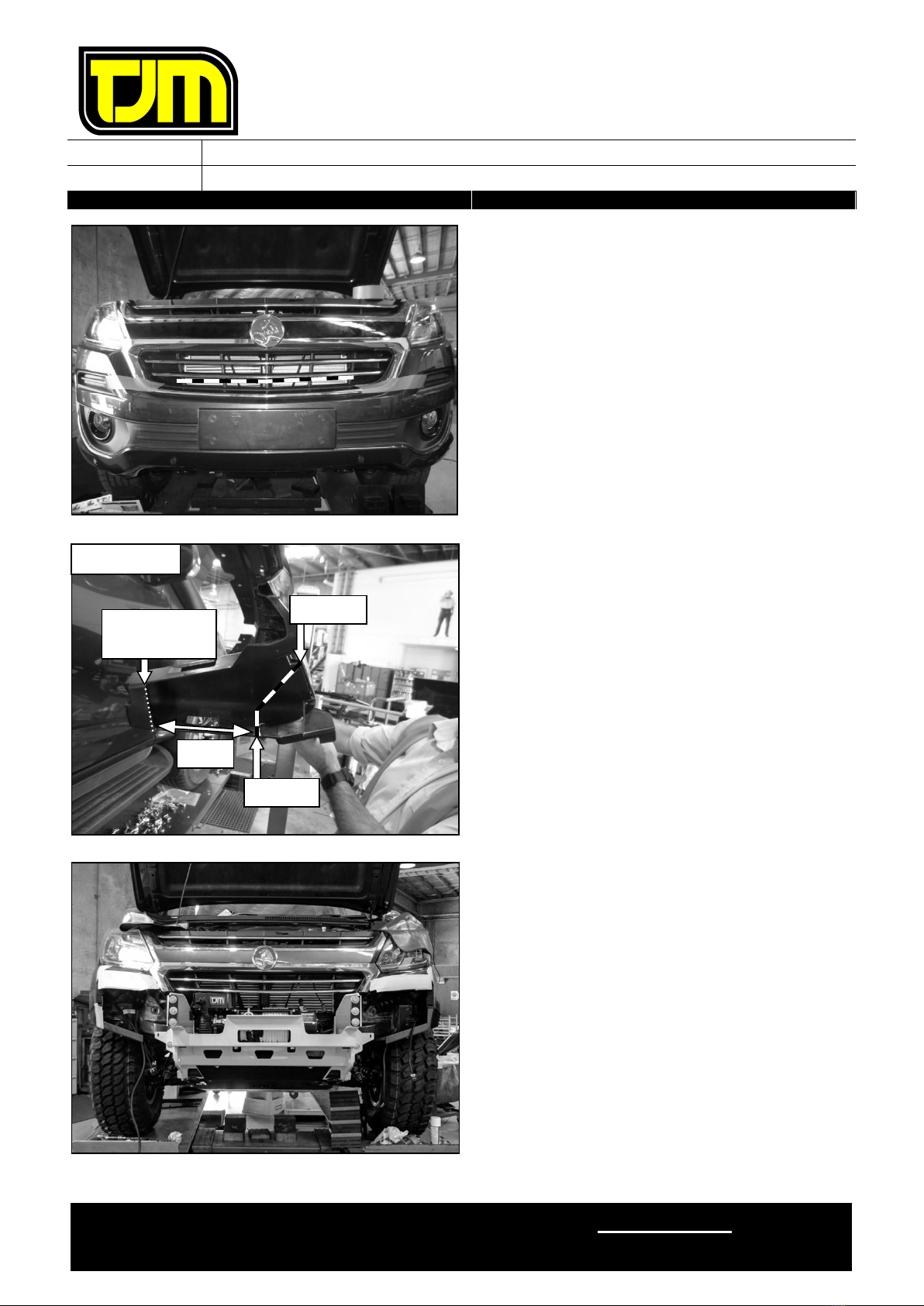
2. Remove (& retain) the number-plate,
discarding the fasteners.
3. Remove (& retain) the screws (8) that are
securing the top of the grille/radiator shroud.
RHS SHOWN
RHS SHOWN
STEP 1.1
STEP 1.2
STEP 1.3
15mm
RHS SHOWN

FITTING INSTRUCTIONS
Product:
T13 Outback Deluxe Frontal Protection System
Vehicle:
Holden Colorado 2016+
Part No.
070SB13L32R
For product warranty, please refer to our website, www.tjm.com.au
File: F-13409
Page 5 of 28
28/03/2017
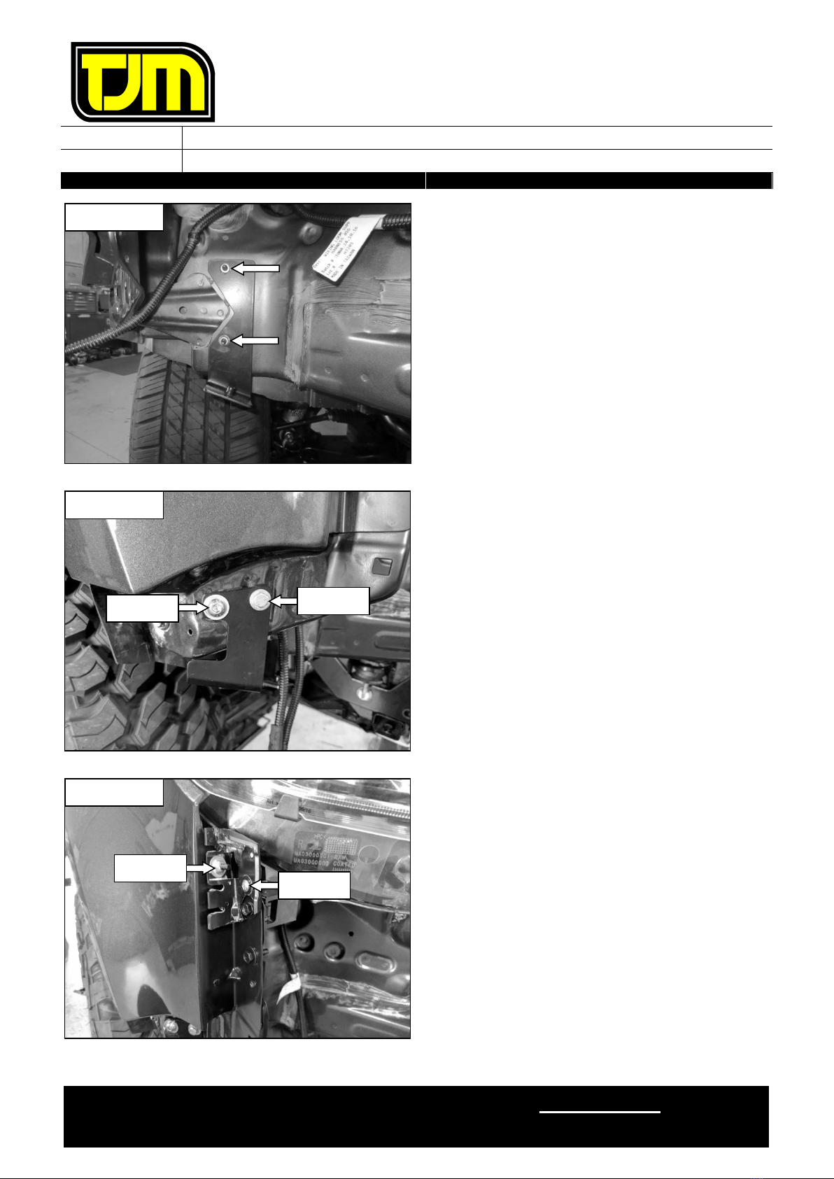
4. From each side of the bumper assembly,
remove the screws (2 each side) that are
securing the wheel arch liners to the bumper
assembly, retaining/discarding the screws as
indicated.
Step 5 only applies if fog-lights are
installed to the bumper assembly.
Otherwise, please proceed to step 6.
5. Disconnect the fog-lights wiring harness from
the vehicle.
6. Remove (& discard) the indicated fasteners
that are securing the bumper assembly in
place.
7. Repeat the previous step for the opposite side
of the vehicle.
8. On both sides of the vehicle, gently pull the
bumper assembly outwards from the vehicle,
at the indicated location, so as to release the
sides of the bumper assembly from the
vehicle.
RHS SHOWN
LHS SHOWN
LHS SHOWN
RETAIN
DISCARD
FITTING INSTRUCTIONS
Product:
T13 Outback Deluxe Frontal Protection System
Vehicle:
Holden Colorado 2016+
Part No.
070SB13L32R
For product warranty, please refer to our website, www.tjm.com.au
File: F-13409
Page 6 of 28
28/03/2017
9. Remove (& retain) the bumper assembly from
the vehicle & carefully set it aside.
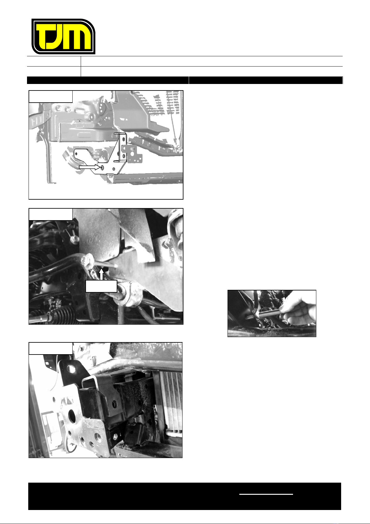
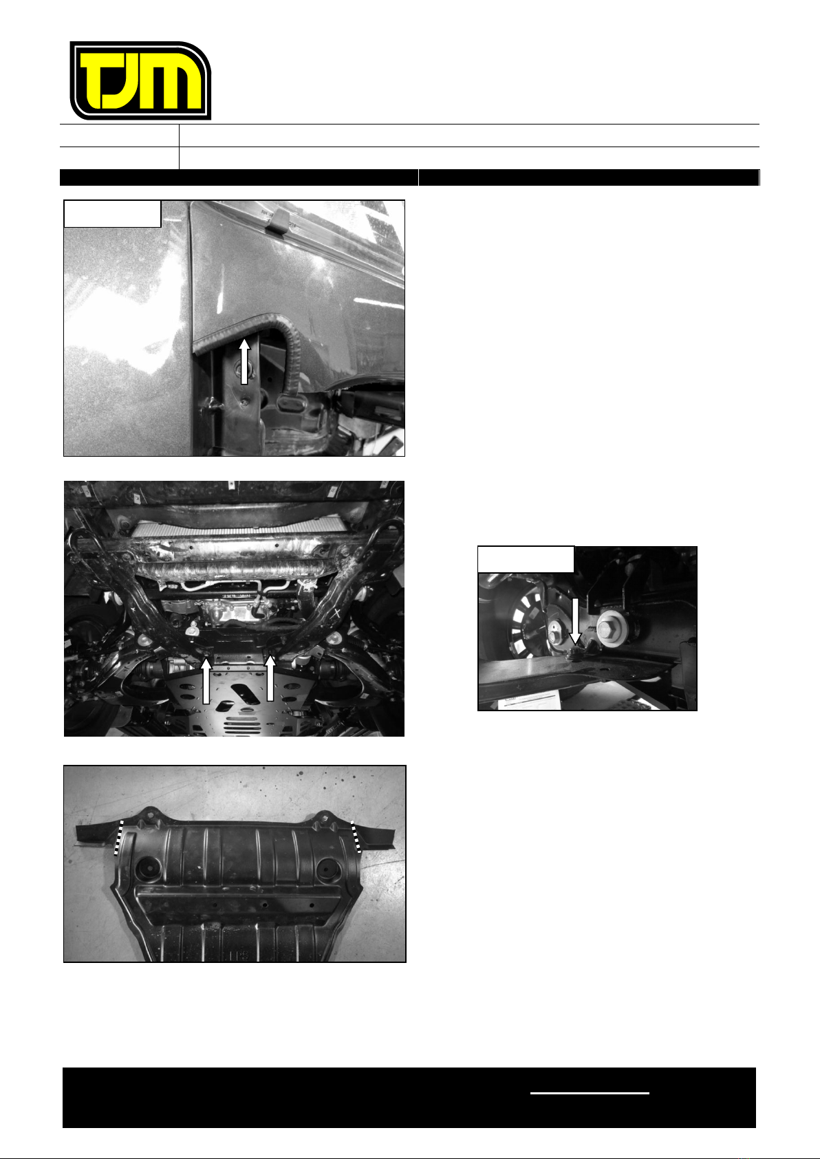
10. Remove (& retain) the steering guard from the
vehicle, retaining the fasteners (6).
11. Remove (& discard) the fasteners (2) that are
securing the tow points to the chassis cross-
member.
12. Loosen, but do not remove, the indicated
fasteners (2), so as to allow the front of the
tow points to drop slightly (in conjunction with
step 13 below).
STEP 11
STEP 11
STEP 12
FITTING INSTRUCTIONS
Product:
T13 Outback Deluxe Frontal Protection System
Vehicle:
Holden Colorado 2016+
Part No.
070SB13L32R
For product warranty, please refer to our website, www.tjm.com.au
File: F-13409
Page 7 of 28
28/03/2017
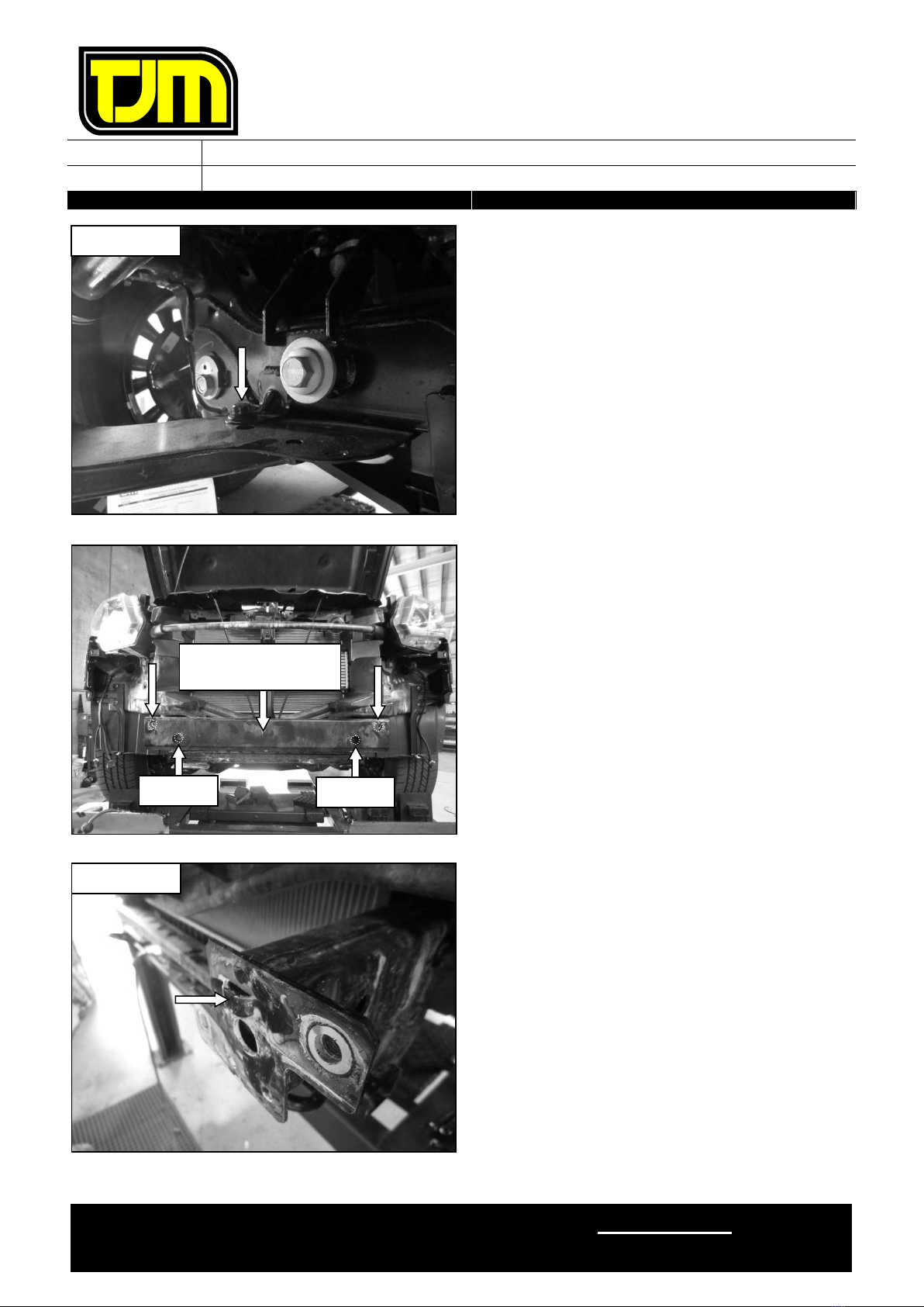
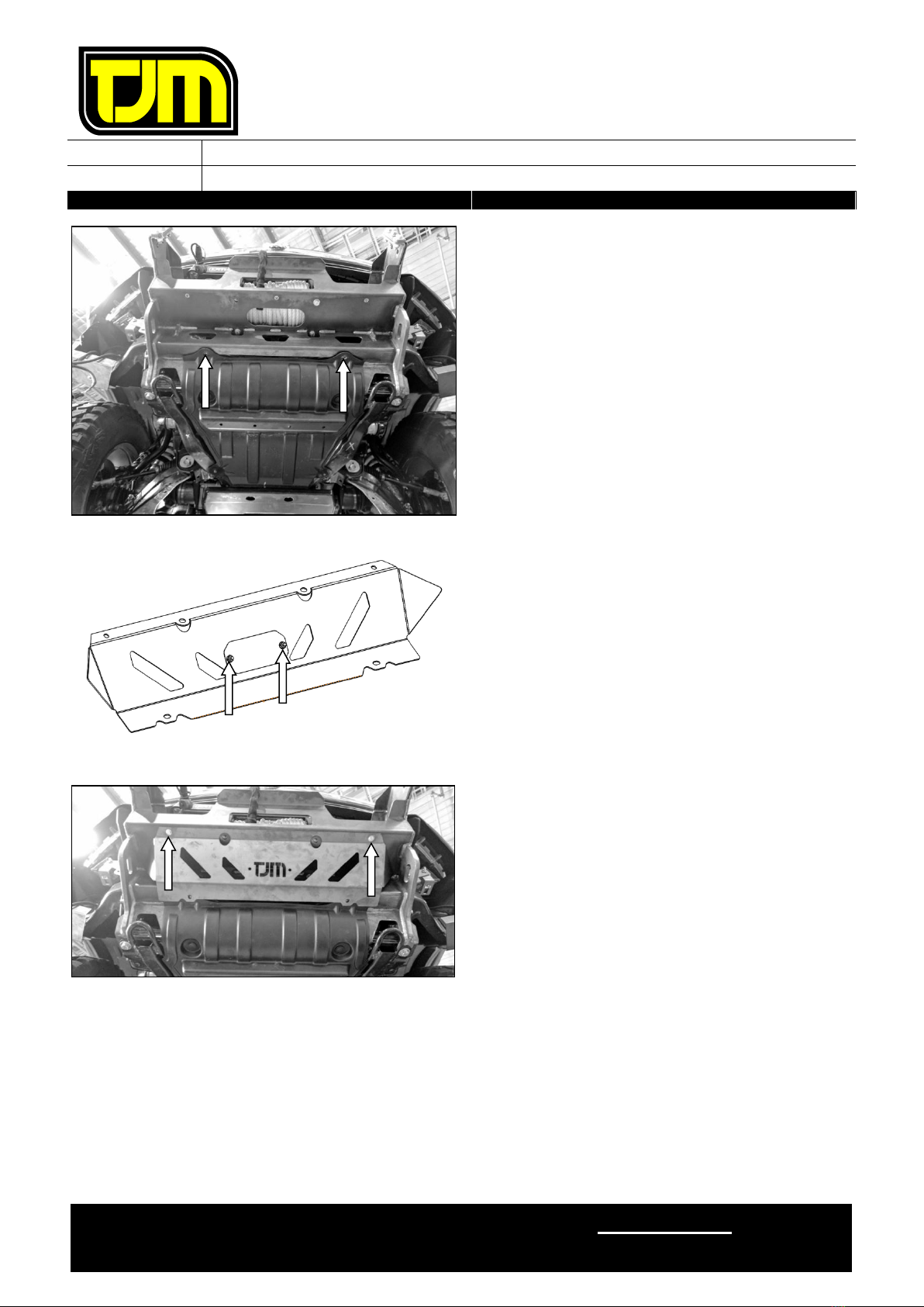
13. Loosen, but do not remove, the indicated
fasteners (1 each side), so as to allow the
front of the tow points to drop slightly (in
conjunction with step 12 above).
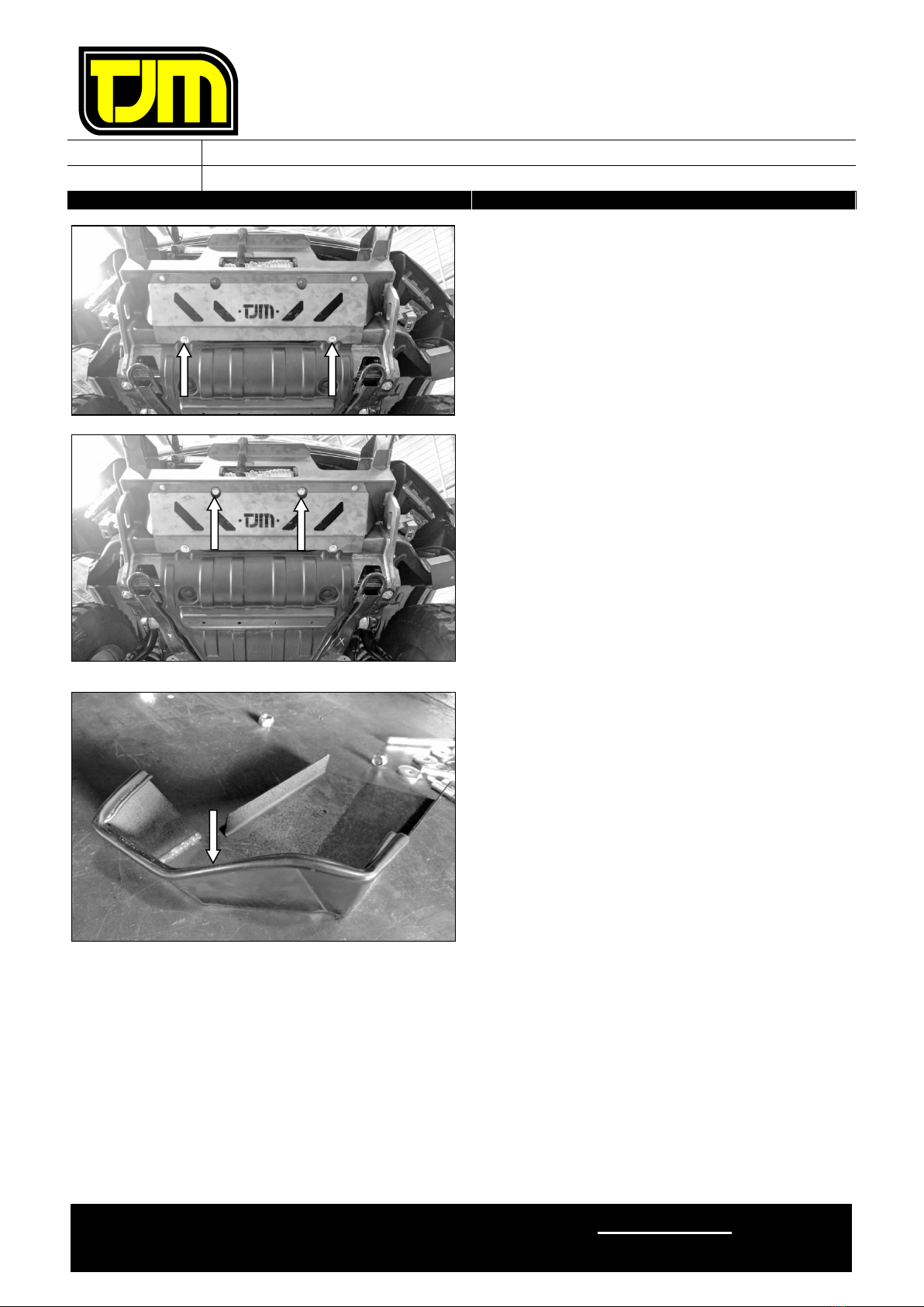
14. Remove (& discard) the front intrusion beam,
retaining the indicated fasteners (2), whilst
discarding the rest.
15. Connect the indicator/parker patch harness to
the vehicle. Check operation of the
indicator/parker lights to ensure correct
function.
16. Cut or grind the indicated tabs off the end of
each chassis rail.
17. Treat any newly exposed metal with a rust
preventative.
RETAIN
RETAIN
FRONT INTRUSION
BEAM
RHS SHOWN
LHS SHOWN

FITTING INSTRUCTIONS
Product:
T13 Outback Deluxe Frontal Protection System
Vehicle:
Holden Colorado 2016+
Part No.
070SB13L32R
For product warranty, please refer to our website, www.tjm.com.au
File: F-13409
Page 8 of 28
28/03/2017
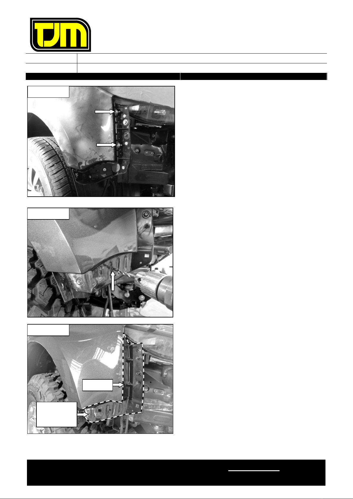
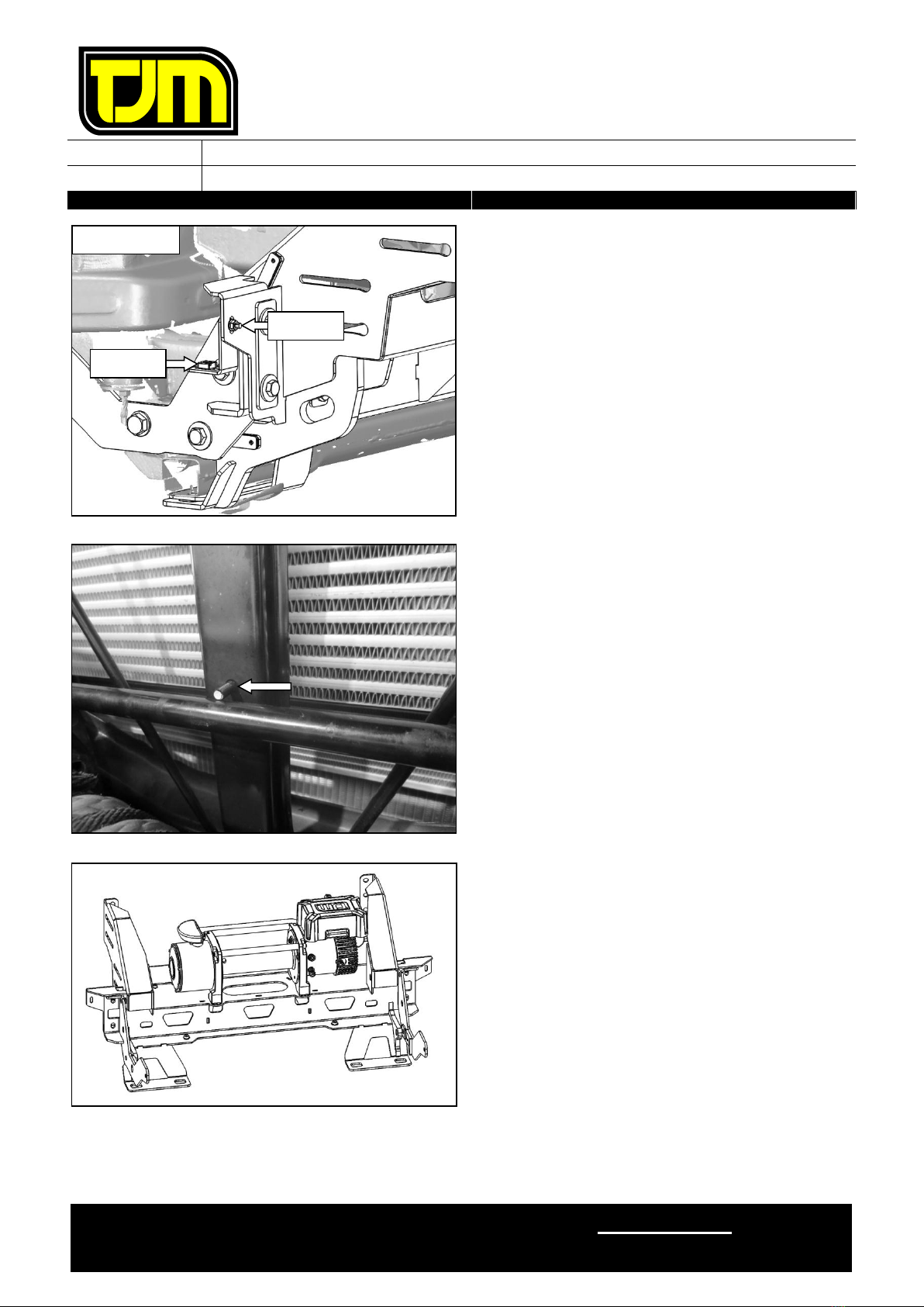
18. Remove and retain the 2 indicated fasteners
and associated bracket from both sides of the
vehicle.
19. Mark a point 75mm down from the top rear
corner of the bumper retention clip.
20. Mark a point 45mm down from the top front
corner of the bumper retention clip.
21. Mark a straight line to join the two points.
22. Drill out the 5 rivets securing the bumper
retaining clip with a 4mm drill bit.
RHS SHOWN
RHS SHOWN
RHS SHOWN
7
7
75
5
5m
m
mm
m
m
4
4
45
5
5m
m
mm
m
m
STEP 21
FITTING INSTRUCTIONS
Product:
T13 Outback Deluxe Frontal Protection System
Vehicle:
Holden Colorado 2016+
Part No.
070SB13L32R
For product warranty, please refer to our website, www.tjm.com.au
File: F-13409
Page 9 of 28
28/03/2017
23. Remove (and retain) the two indicated nuts,
then remove the bumper retaining clip from
the vehicle.
24. Trim the bumper retaining clip along the line
marked in step 21.
25. Drill the indicated, existing rivet hole in the
vehicle body out to 6mm.
26. Cut and grind the lower bumper retaining clip
stud so it sits flush with the vehicle bodywork,
as shown.
27. Mask surrounding bodywork and the vehicle’s
headlights, then paint all areas previously
beneath the bumper retaining clip with a black
rust preventing paint. Ensure all newly
exposed metal is thoroughly coated.
RHS SHOWN
RHS SHOWN
RHS SHOWN
STEP 26
PAINT
INDICATED
AREA
FITTING INSTRUCTIONS
Product:
T13 Outback Deluxe Frontal Protection System
Vehicle:
Holden Colorado 2016+
Part No.
070SB13L32R
For product warranty, please refer to our website, www.tjm.com.au
File: F-13409
Page 10 of 28
28/03/2017
28. Secure the inner body cover mount at the
indicated location using fasteners retained in
step 18.
29. Secure outer body cover mount through the
indicated hole with an M6 x 1.0 x 20mm Hex
Head Bolt (1), 1/4" x Ø5/8” Flat Washers (2)
and M6 x 1.0 Nyloc Nut (1).
30. Secure outer body cover mount through the
indicated hole with an M8 x 1.25 x 20mm
Button Head Bolt (1), M8 x Ø19mm Flat
Washers (2) and M8 Nyloc Nut (1).
Repeat the previous two steps on opposite side
of vehicle.
31. Fasten the bumper retaining clip at the
indicated location using fasteners retained
during step 23.
32. Secure the bumper retaining clip at the
indicated location using a M4 x 16mm pan
head screw (1), M4 x Ø9-12mm washers (2)
and M4 Nyloc (1).
Repeat the previous two steps on opposite side
of vehicle.
RHS SHOWN
RHS SHOWN
STEP 30
STEP 29
STEP 31
STEP 32
RHS SHOWN

FITTING INSTRUCTIONS
Product:
T13 Outback Deluxe Frontal Protection System
Vehicle:
Holden Colorado 2016+
Part No.
070SB13L32R
For product warranty, please refer to our website, www.tjm.com.au
File: F-13409
Page 11 of 28
28/03/2017
33. Mark the airdam for trimming using the
following process:
33.1. Mark a point 200mm out horizontally
from the underside of the airdram
outrigger.
33.2. Mark a point 25mm out horizontally from
the topside of the body member.
33.3. Draw a straight line between the two
points.
33.4. Draw a line horizontally across the short
face of the airdam, joining with the line
marked in step 33.3.
33.5. Draw a line 90mm out from and parallel
with the back edge of the airdam, as
shown.
33.6. Join the ends of the lines marked in
steps 33.4 and 33.5 with a straight line.
33.7. Measure and mark a line 55mm out from
the indicated point on the airdam so that
it is inline with the indicated edge.
33.8. Draw a line perpendicular to the one
marked in step 33.7 back towards the
vehicle body.
33.9. Mark a line from the end of the one
drawn in step 33.8, along the
intersection of the lower airdam faces.
33.10. Draw a line joining the ends of those
marked in step 33.2 and 33.9.
LHS SHOWN
200mm
25mm
LHS SHOWN
90mm
STEP 33.1
STEP 33.2
STEP 33.3
STEP 33.4
RHS SHOWN
55mm
POINT
EDGE
STEP 33.9
STEP 33.8
STEP 33.10
STEP33.7
FITTING INSTRUCTIONS
Product:
T13 Outback Deluxe Frontal Protection System
Vehicle:
Holden Colorado 2016+
Part No.
070SB13L32R
For product warranty, please refer to our website, www.tjm.com.au
File: F-13409
Page 12 of 28
28/03/2017
34. Position the chassis mount as shown and
loosely secure at the indicated location using
an M14 x 1.5 x 45mm hex bolt (1), 9/16” x
Ø1-1/8” flat washers (2) & M14 nyloc nut (1).
35. Position an M10 x 1.25 x 100mm hex bolt (1)
& M10 x Ø30mm flat washer (1) at the
indicated location.
36. Position an M10 x 66mm long tube spacer
over the fastener from the previous step, then
loosely secure the rear of the chassis mount in
place, using the fasteners from the previous
step, an M10 x Ø30mm flat washer (1) & M10
nyloc nut (1).
37. Position a chassis rail bracket over the inside
of the chassis rail as shown opposite.
RHS SHOWN
RHS SHOWN
STEP 35
RHS SHOWN

FITTING INSTRUCTIONS
Product:
T13 Outback Deluxe Frontal Protection System
Vehicle:
Holden Colorado 2016+
Part No.
070SB13L32R
For product warranty, please refer to our website, www.tjm.com.au
File: F-13409
Page 13 of 28
28/03/2017
38. Loosely secure the chassis mount and chassis
rail bracket in place, using an M10 x 1.25 x
80mm hex bolt (1), M10 x Ø30mm flat
washers (2), M10 nyloc nut (1) & M10 x 50mm
long tube spacer.
39. Repeat steps 34 to 38 for the opposite side of
the vehicle then tighten fasteners to the
torque specified on page 1.
40. Loosely secure the winch frame in place at the
indicated location using M10 x 1.25 x 30mm
hex bolts (2), M10 spring washers (2), and
M10 Washer Plates (2) .
41. On both sides of the winch frame, insert a
4mm spacer (shown below) between the
chassis cross member and the lower winch
frame mount.
RHS SHOWN
STEP 38
RHS SHOWN
STEP 41

FITTING INSTRUCTIONS
Product:
T13 Outback Deluxe Frontal Protection System
Vehicle:
Holden Colorado 2016+
Part No.
070SB13L32R
For product warranty, please refer to our website, www.tjm.com.au
File: F-13409
Page 14 of 28
28/03/2017
42. Loosely secure the lower winch frame mounts
to the vehicle using M10 x 1.25 x 40mm hex
bolt (4), M10 x Ø30mm flat washer (4) & M10
spring washers (4). Ensure these bolts also
pass through the OE tow points.
Use as many 2mm spacers as required to
ensure there is minimal gap between the
winch frame and chassis cross member.
43. Centre the winch frame to the vehicle body
and tighten the fasteners installed in steps 40
and 42 to the torque settings specified on
page 1.
44. Using M10 x 1.25 x 40mm hex bolts (2),
Chassis end plate washer (F-13880), M10 x
Ø30mm Flat Washers (4) and M10 Nylocs (2),
loosely secure the winch frame to the chassis
mounts at the indicated positions.
USE M10 X Ø30MM FLAT WASHERS
WHERE NECESSARY AS SPACERS BETWEEN
THE WINCH FRAME AND CHASSIS MOUNT
ENSURE BOLTS ARE ORIENTED
CORRECTLY, AS SHOWN OPPOSITE. LOWER
BOLT HEAD ON FRONT FACE AND UPPER
NUT ON FRONT FACE.
RHS SHOWN

FITTING INSTRUCTIONS
Product:
T13 Outback Deluxe Frontal Protection System
Vehicle:
Holden Colorado 2016+
Part No.
070SB13L32R
For product warranty, please refer to our website, www.tjm.com.au
File: F-13409
Page 15 of 28
28/03/2017
45. Loosely secure the chassis mount to the winch
frame using the following fasteners:
45.1. M12 x 1.25 x 120mm hex bolt (1), 1/2"
x Ø1-1/4” Flat Washers (2), M12 Nyloc
nut (1)
45.2. M12 x 1.25 x 60mm hex bolt (1), 1/2" x
Ø1-1/4” Flat Washers (2), M12 Nyloc
nut (1).
46. Use as many spacers as required around the
fasteners installed in step 45 to fill the void
between the chassis mount and winch frame.
47. Tighten all fasteners to the values specified on
page 1.
48. Repeat steps 44 - 47 for the opposite side of
the vehicle.
49. Fit clamp Angle bracket to inboard face of
winch frame and washer plate to front using
M12 x 1.25 x 35mm bolts (3), 1/2" x Ø1-1/4”
Flat Washers (6) & M12 nyloc nuts (3).
IMPORTANT –FIT M12 BOLT ASSEMBLY WITH
BOLT HEAD ON FRONT FACE.
50. Align plate with existing holes and tighten to
specified torque. Check holes and slots align
after tightening to allow easy bolt
fitment/clearance.
Repeat on opposite side of vehicle.
STEP 45.1
STEP 45.2
INSERT
SPACERS AS
REQUIRED
Holes must
align
NUTS
TO INSIDE!
RHS SHOWN
RHS SHOWN
RHS SHOWN
FITTING INSTRUCTIONS
Product:
T13 Outback Deluxe Frontal Protection System
Vehicle:
Holden Colorado 2016+
Part No.
070SB13L32R
For product warranty, please refer to our website, www.tjm.com.au
File: F-13409
Page 16 of 28
28/03/2017
51. Loosely secure the wing guard bracket to the
winch frame using a M6 x 1.0 x 20mm hex bolt
(1), 1/4" x Ø5/8” Flat Washer (1) and M6
flange nut (1).
52. Insert an M8 cage nut (1) into the wing guard
bracket so the nut is situated on top of the
bracket.
Repeat on opposite side of vehicle.
Steps 53 through to 55 only apply if a
winch is to be fitted. Otherwise, please
proceed to step 56.
53. If required, perform additional trimming of the
air dams in order to fit the winch.
54. Remove the indicated lower stud and treat any
newly exposed metal with a rust preventative.
55. Locating the winch & control box as shown,
refer to the winch fitting instructions & fit the
winch to the winch frame.
At this stage, tighten rear fasteners
only.
Supplementary kit 076SKITA32R is
required for fitment of TJM Torq winch
RHS SHOWN
STEP 51
STEP 52
FITTING INSTRUCTIONS
Product:
T13 Outback Deluxe Frontal Protection System
Vehicle:
Holden Colorado 2016+
Part No.
070SB13L32R
For product warranty, please refer to our website, www.tjm.com.au
File: F-13409
Page 17 of 28
28/03/2017
56. Cut the bumper along the previously marked
trim lines, using the intersection between black
and painted bumper sections as a guide to join
marked lines.
57. Cut the grille through the ribs on the underside
of the lower spar, as shown.
58. Mark a vertical line on the grille support, 90mm
out from the indicated reference edge.
59. Join the end of the line marked in step 58 to
the edge of the grille cut performed in step 56.
60. Re-fit the upper section of the bumper
assembly back to the vehicle, using the
fasteners retained in steps 3& 4.
90mm
STEP 59
STEP 58
REFERENCE
EDGE
RHS SHOWN
FITTING INSTRUCTIONS
Product:
T13 Outback Deluxe Frontal Protection System
Vehicle:
Holden Colorado 2016+
Part No.
070SB13L32R
For product warranty, please refer to our website, www.tjm.com.au
File: F-13409
Page 18 of 28
28/03/2017
61. Fit pinch weld to bumper as shown, on both
sides.
62. Tighten the OE fasteners loosened in steps 12
and 13.
63. Trim the OE steering guard along the contour,
as shown opposite.
RHS SHOWN
RHS SHOWN
FITTING INSTRUCTIONS
Product:
T13 Outback Deluxe Frontal Protection System
Vehicle:
Holden Colorado 2016+
Part No.
070SB13L32R
For product warranty, please refer to our website, www.tjm.com.au
File: F-13409
Page 19 of 28
28/03/2017
64. Re-fit the OE underbody guards as per their
original installation, use the retained OE
fasteners for all mounting points except for
the indicated position.
65. Fit the supplied logo backing plate to the
inside of the centre guard, as shown, using M6
x 1.0 x 20mm button head bolts (2), 1/4" x
Ø5/8” Flat Washers (2) and M6 flange nuts
(2).
66. Position the centre guard as shown opposite,
sandwiching the OE guard between the centre
guard and winch frame.
67. Fasten the front of the centre guard to the
winch frame using M6 x 1.0 x 20mm hex head
bolts (2), M6 spring washers (2) and 1/4" x
Ø5/8” Flat Washers (2).
FITTING INSTRUCTIONS
Product:
T13 Outback Deluxe Frontal Protection System
Vehicle:
Holden Colorado 2016+
Part No.
070SB13L32R
For product warranty, please refer to our website, www.tjm.com.au
File: F-13409
Page 20 of 28
28/03/2017
68. Fasten the rear of the centre guard and OE
guard to the winch frame using M8 x 1.25 x
35mm Hex Head bolts (2), M8 Spring Washers
(2) and 5/16” x Ø1-1/4” Flat Washers (2).
If no winch has been fitted, proceed to
step 70
69. Install and tighten the front winch bolts,
supplied with winch.
Proceed to step 71
70. Secure the centre guard at the indicated
location using M10 x 1.25 x 30mm Hex bolts
(2), M10 x Ø30mm Washers and M10 Flange
nuts.
71. Fit the supplied pinch weld to the top edge of
the body cover panels, as shown.
Table of contents
Other TJM Automobile Accessories manuals


Popular Automobile Accessories manuals by other brands


ULTIMATE SPEED
ULTIMATE SPEED 279746 Assembly and Safety Advice

SSV Works
SSV Works DF-F65 manual

ULTIMATE SPEED
ULTIMATE SPEED CARBON Assembly and Safety Advice

Witter
Witter F174 Fitting instructions

WeatherTech
WeatherTech No-Drill installation instructions

TAUBENREUTHER
TAUBENREUTHER 1-336050 Installation instruction