TJM T15 User manual

FITTING INSTRUCTIONS
Product:
T15 Signature Frontal Protection System
Vehicle:
Ford Everest
Part No.
070AP15N20A
For product warranty, please refer to our website, www.tjm.com.au
F-11968.docx
Page 1 of 28
25/10/2022
Australian Standards Relating to Installing Vehicle Frontal Protection Systems (VFPS): AS 4876.1-2002
a) Do not attach V.F.P.S. to vehicle using anchorages not intended for this purpose (e.g. engine mounting bolts), other than those
specified by the V.F.P.S. manufacturer in this instruction.
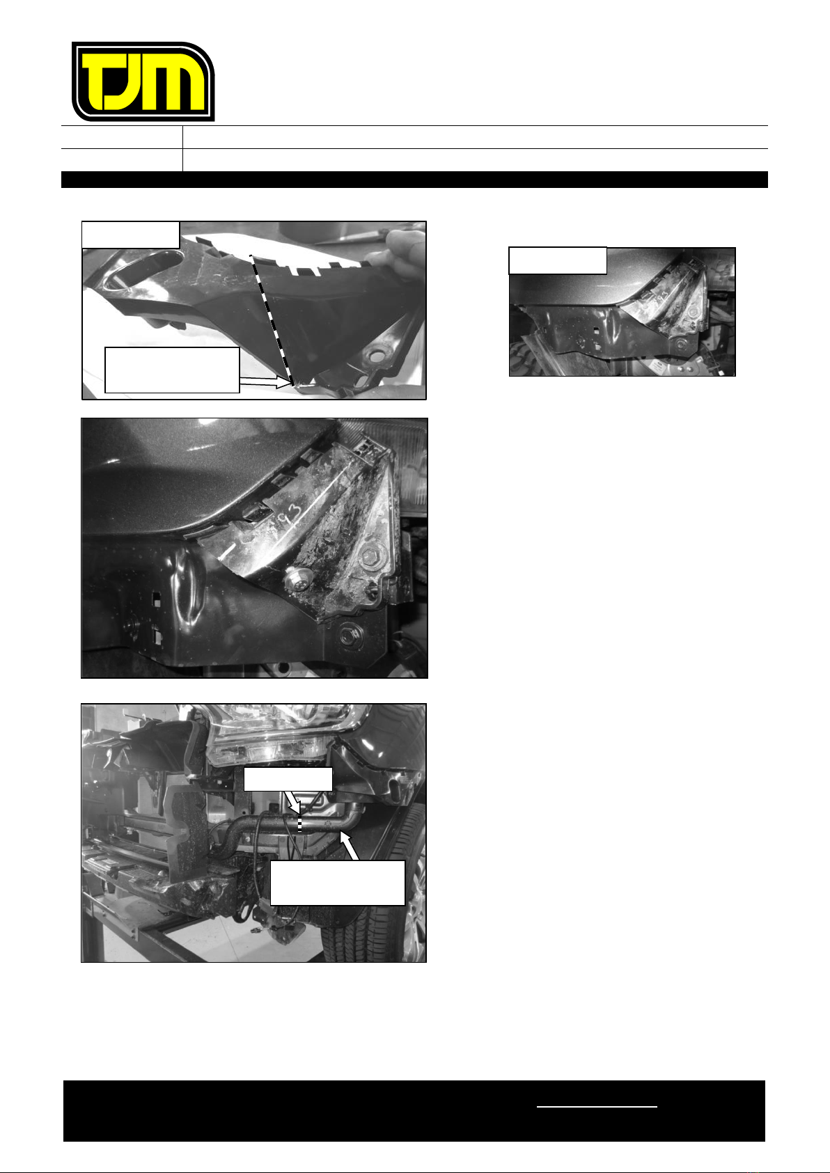
b) Do not use this product for any vehicle make or model other than those specified by the V.F.P.S. manufacturer (as above).
c) Do not remove any plaques or labels from the V.F.P.S.
d) Do not modify the structure of the V.F.P.S. in any way.
•Read instructions fully before commencing fitment.
•076SKITB20A and 946TQEXT500 supplementary kits may also be required
for vehicles fitted with a radar.
•076PSHOUSE supplementary kit may be required for vehicles fitted with 6
front parking sensors.
•The fitment of TJM products does not nullify the OE manufacturer's
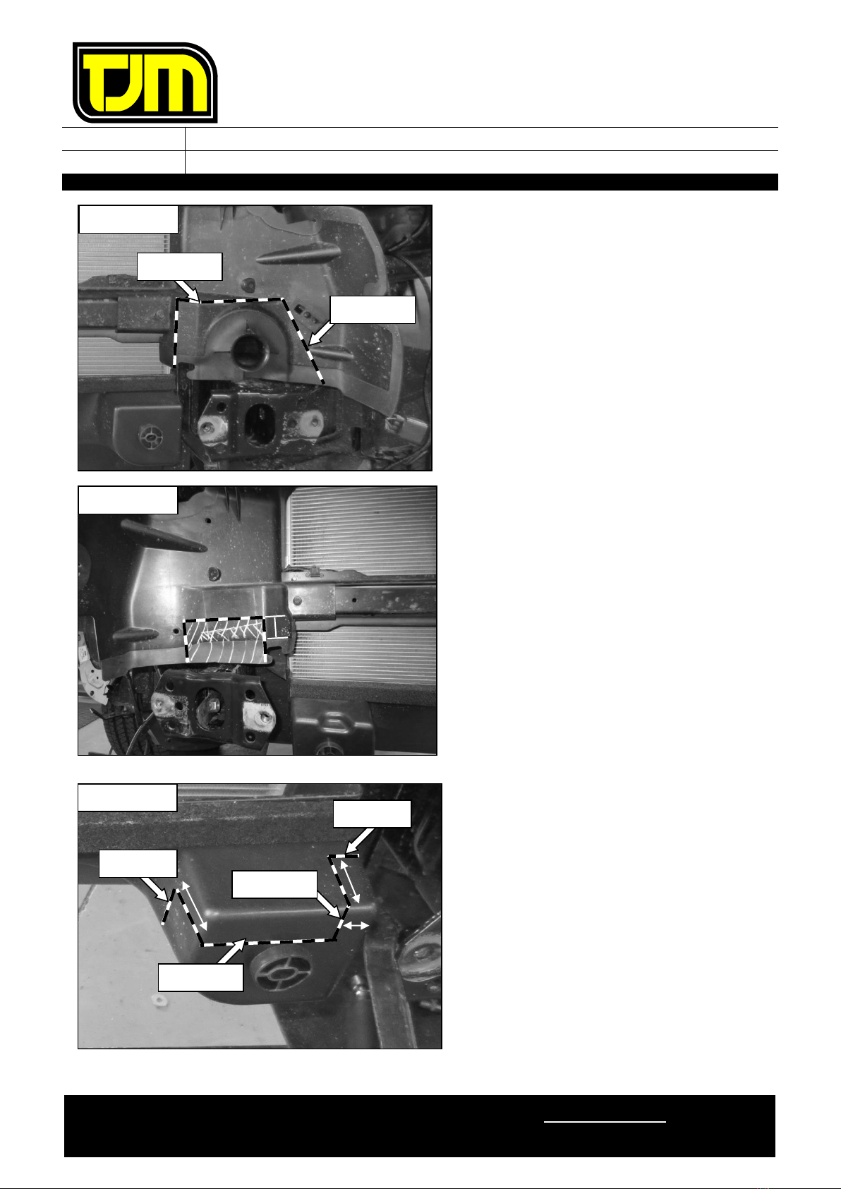
operating guidelines and/or warnings. Ensure you are familiar with and
adhere to the usage instructions specified by the manufacturer in the
owner's manual or other official documentation.
•Left hand and Right hand components are determined as seated in the
vehicle.
•Check for (and remove) any build up in all captive nuts fitted to the FPS.
•Be aware that a number of government / fleet departments require that the
tow points be painted red.
•Ensure that the “Rated Recovery Point Label” is affixed alongside the
compliance label, in the driver’s side doorjamb.
•When fitting accessories to TJM products (ie. driving lights and aerials),
ensure suitable washer plates are used under the mounting surface that
allow the accessory to be secured in a way that prevents it from damaging
the product.
•When removing protective coatings, ensure all new edges are deburred,
clean any swarf from the area and apply rust preventative to exposed
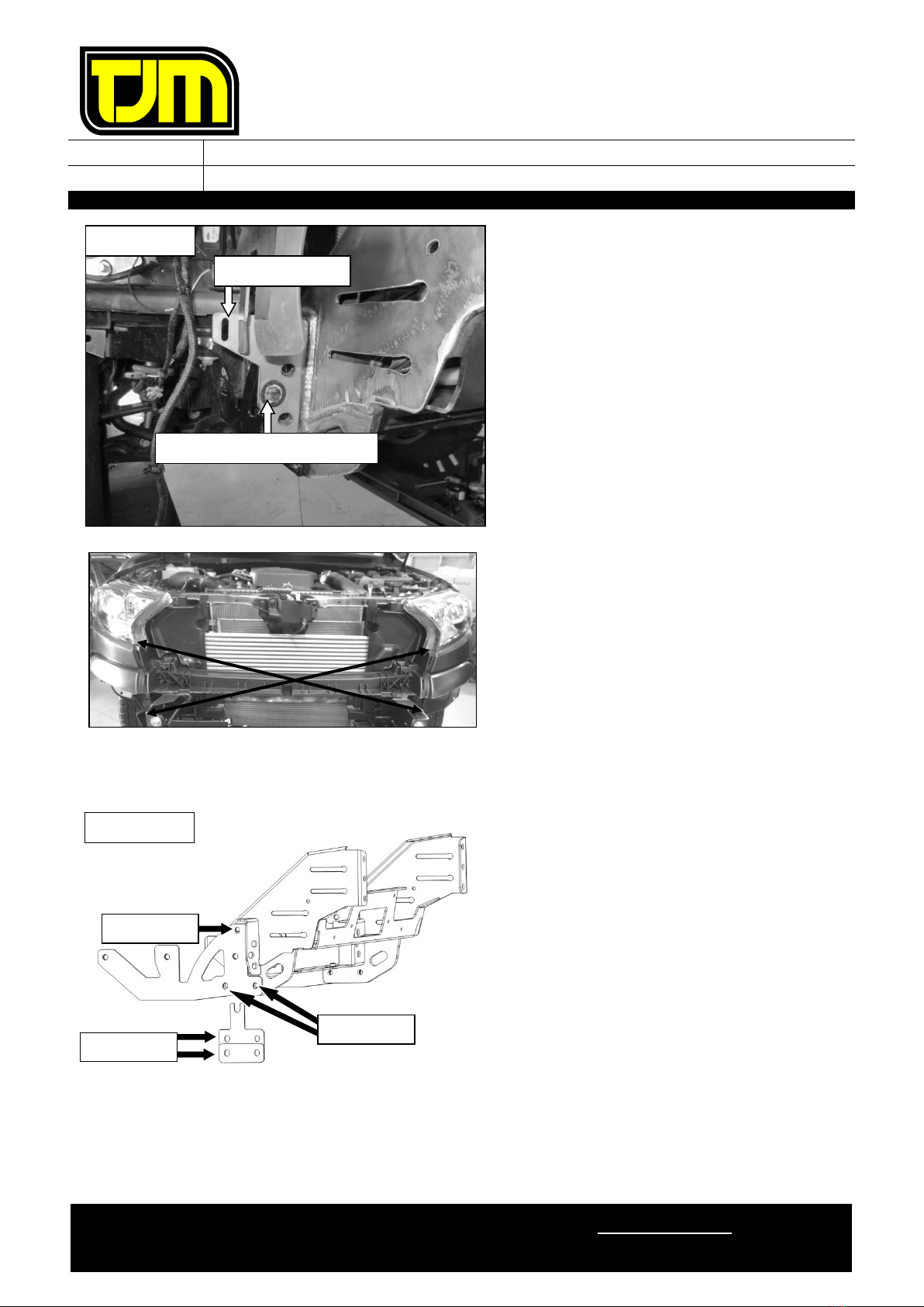
surfaces.
Bolt tensions
Dia. (mm)
Nm
ft.lbs
Dia. (inch)
Nm
ft.lbs
All bolt tensions are
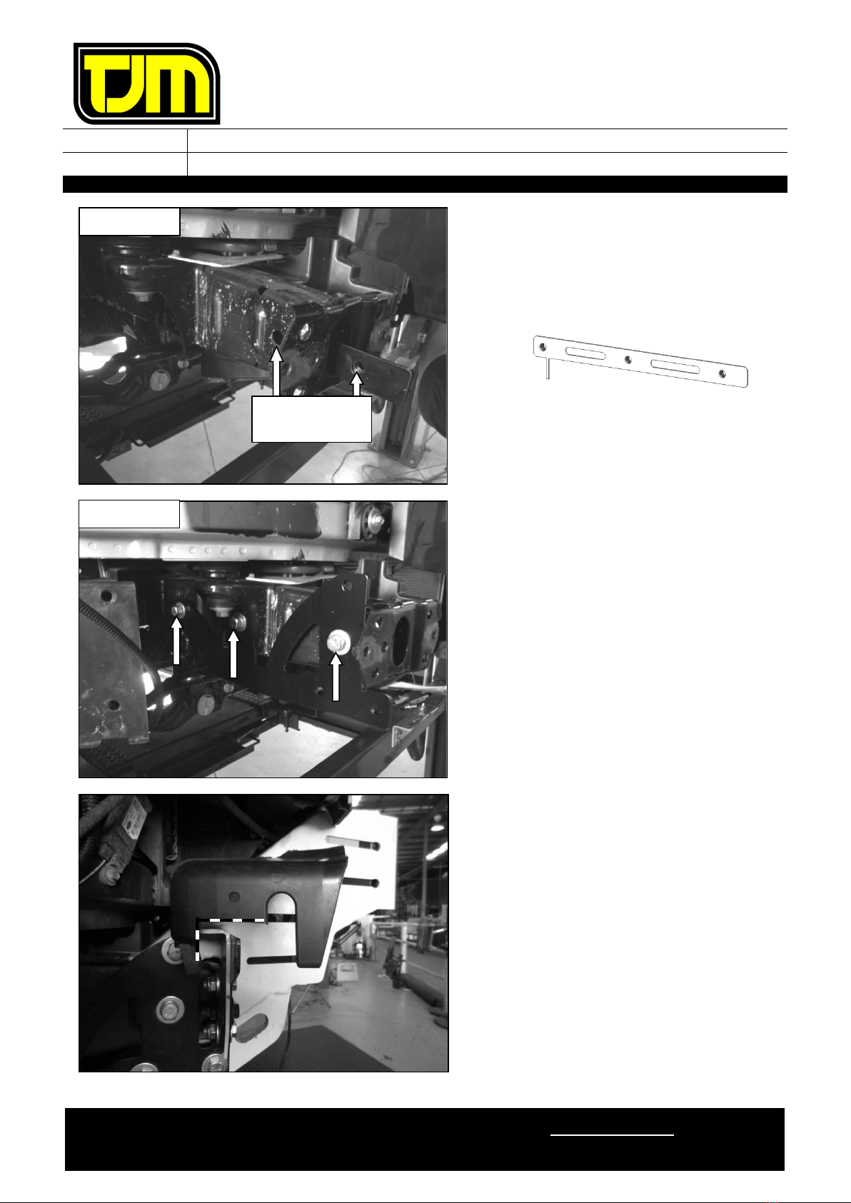
as follows unless
otherwise
specified.
5
5
4
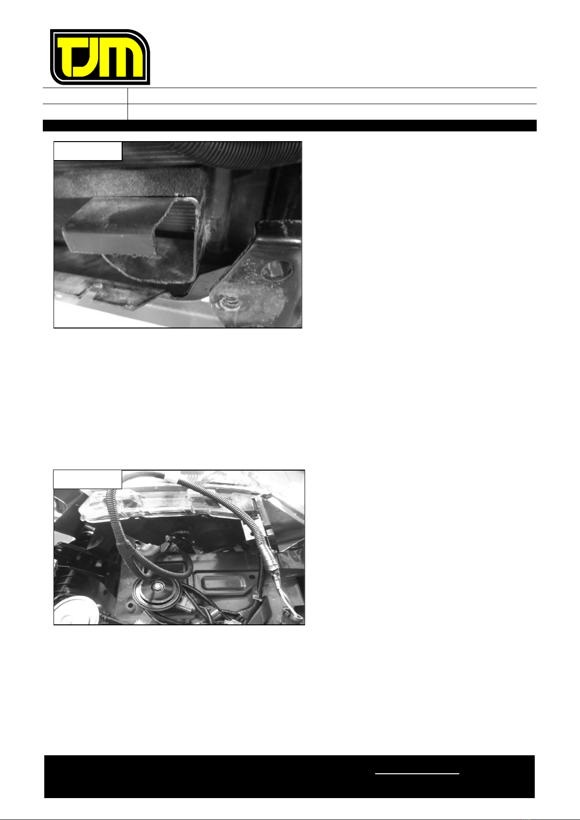
1/4”
9
7
6
9
7
5/16”
22
15
8
22
16
3/8”
33
27
10
44
32
7/16”
55
43
12
77
57
1/2”
86
66
FITTING INSTRUCTIONS
Product:
T15 Signature Frontal Protection System
Vehicle:
Ford Everest
Part No.
070AP15N20A
For product warranty, please refer to our website, www.tjm.com.au
F-11968.docx
Page 2 of 28
25/10/2022

FITTING INSTRUCTIONS
Product:
T15 Signature Frontal Protection System
Vehicle:
Ford Everest
Part No.
070AP15N20A
For product warranty, please refer to our website, www.tjm.com.au
F-11968.docx
Page 3 of 28
25/10/2022
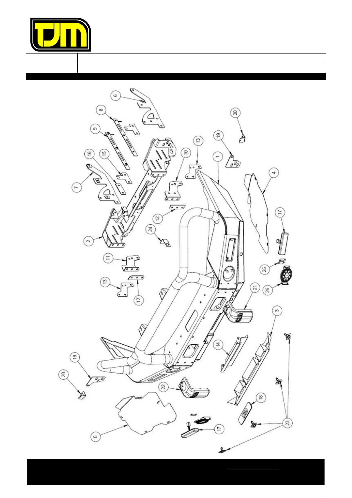
ITEM
NO.
Description
Qty
Part
Number
PARTS LIST
1
T15 Signature FPS
1
F-10229
2
Chassis Mount / Winch Frame
1
F-10773
3
Center Guard
1
F-10991
4
Wing Guard LH
1
F-10569L
5
Wing Guard RH
1
F-10569R
FITTING KIT
6
Chassis Brace LH
1
F-1072L
7
Chassis Brace RH
1
F-1072R
8
Inner Chassis Nut-Plate LH
1
F-1075L
9
Inner Chassis Nut-Plate RH
1
F-1075R
10
Bend Angle LH
1
F-10861L
11
Bend Angle RH
1
F-10861R
12
Bending Washer Plate
2
F-8052
13
Sliding Washer Plate
2
F-10874
14
Fairlead Cover
1
F-10291
15
Spacer 2mm
2
F-8918
16
Spacer 4mm
2
F-8921
17
LED Parker/Indicator
2
92750
18
Winch Slot Cover Insert
1
92106
19
Winch Frame Washer Plate
2
F-11003
20
Wing Guard Bracket
2
F-11004
21
Bumperette LH
1
F-2854L
22
Bumperette RH
1
F-2854R
23
Parking Sensor Housing Kit
4
F-5417
24
Fusebox Vent Bracket
1
F-9896
25
Foglight Washer Plate
4
88057
26
Foglight Blanking Cover
2
92091
N/A
Bumper Trim Template
1
F-11766-T
N/A
12.7mm Plastic Plug
4
K0765
N/A
Nylon Plug
4
K0665
N/A
Rated Recovery Point Label
1
HC0064
N/A
Recovery Point Use Guide
1
F-1768
N/A
Pinch-Weld (750mm Long)
1
93154
N/A
Rubber Grommet
1
92645
N/A
Christmas Tree Plug
1
K0666
N/A
Vent Hose (530mm)
1
K3075
N/A
Cable Tie (300mm)
8
K1148
N/A
Foam Tape (750mm)
1
K1361
ITEM
NO.
Description
Qty
Part
Number
BOLT KIT
N/A
M6 x 1.0 x 20mm Hex Head Bolt
21
K0550
N/A
M6 x 1.0 x 30mm Hex Head Bolt
2
K3220
N/A
M6 x 1.0 Flange Nut
25
K3033
N/A
M6 x 1.0 Cage Nut Type B
6
K1550
N/A
M6 x 1.0 Nyloc Nut
2
K0605
N/A
M6 Spring Washer
12
K0915
N/A
M6 x Ø12.5mm Flat Washer
14
K0897
N/A
M6 x Ø18mm x 1.6mm Flat Washer
11
K2905
N/A
M8 x 1.25 x 35mm Hex Bolt
4
K0555
N/A
M8 x Ø24mm Flat Washer
6
-
N/A
M8 Spring Washer
2
K0620
N/A
M8 x 1.25 Nyloc Nut
2
K0606
N/A
M8 Cage Nut
2
K1560
N/A
M10 x 1.25 x 20mm Hex Bolt
2
K0938
N/A
M10 x 1.25 x 30mm Hex Bolt
8
K0564
N/A
M10 x 1.25 Nyloc Nut
8
K3099
N/A
M10 x 1.25 Flange Nut
2
K3036
N/A
M10 x Ø30mm Flat Washer
16
WSST-W13
N/A
M10 x Ø20mm Flat Washer
2
-
N/A
M12 x 1.25 x 35mm Hex Bolt
6
K0570
N/A
M12 x 1.25 x 40mm Hex Head Screw
14
K0571
N/A
M12 x 1.25 x 50mm Hex Bolt
4
K0572
N/A
M12 x 1.25 x 90mm Hex Bolt
2
K0976
N/A
M12 x 1.25 Nyloc Nut
20
K1200
N/A
M12 Spring Washer
6
K0977
N/A
1/2" x Ø1-1/4” Flat Washer
46
K0623
FACTORY FITTED
N/A
Rated Recovery Point Label
1
HC0064
N/A
TJM Logo Sticker
1
K3550
N/A
Warning Label - ABC
1
HC0057

FITTING INSTRUCTIONS
Product:
T15 Signature Frontal Protection System
Vehicle:
Ford Everest
Part No.
070AP15N20A
For product warranty, please refer to our website, www.tjm.com.au
F-11968.docx
Page 4 of 28
25/10/2022
1. Cut out templates and attach to bumper.
2. Remove & retain the number-plate, discarding
the fasteners.
3. Using the top of the number plate holes as a
reference, mark a horizontal cut line along the
bumper.
4. From grille centerline mark 85mm wide by
35mm high cuts, 350mm from centerline as
shown. Repeat both sides.
HORIZONTAL CUT LINE
350 mm OUT FROM CENTRE LINE
35mm
85mm BOTH SIDES
TEMPLATE
RHS SHOWN
FITTING INSTRUCTIONS
Product:
T15 Signature Frontal Protection System
Vehicle:
Ford Everest
Part No.
070AP15N20A
For product warranty, please refer to our website, www.tjm.com.au
F-11968.docx
Page 5 of 28
25/10/2022
5. Using a straight edge, join the lower edge of
the cut template to the intersection of the
horizontal cut line and outer vertical line
previously marked. Repeat for the opposite side
of the vehicle.
6. Remove and retain the two fasteners securing
the air intake to the vehicle.
7. Remove and retain the air intake.
8. Remove & retain the plastic clips (5) that secure
the top of the grille/radiator shroud.
LHS SHOWN
INTERSECTION
RHS SHOWN

FITTING INSTRUCTIONS
Product:
T15 Signature Frontal Protection System
Vehicle:
Ford Everest
Part No.
070AP15N20A
For product warranty, please refer to our website, www.tjm.com.au
F-11968.docx
Page 6 of 28
25/10/2022
9. Raise shroud at grill, release and remove clips
underneath.
10. Remove and retain 2 bolts securing top of grille.
11. Inside lower grille area behind air dam, locate,
remove and retain the 2 grille and bumper
retaining bolts.
LHS SHOWN
LHS SHOWN
FITTING INSTRUCTIONS
Product:
T15 Signature Frontal Protection System
Vehicle:
Ford Everest
Part No.
070AP15N20A
For product warranty, please refer to our website, www.tjm.com.au
F-11968.docx
Page 7 of 28
25/10/2022
12. Remove 2 center retaining clips on inside of
grille.
13. Remove 4 screws and 1 plastic clip from center
FUG and discard
14. Remove 10 screws holding lower section of
bumper and discard
RHS SHOWN
RHS SHOWN
LHS SHOWN
FITTING INSTRUCTIONS
Product:
T15 Signature Frontal Protection System
Vehicle:
Ford Everest
Part No.
070AP15N20A
For product warranty, please refer to our website, www.tjm.com.au
F-11968.docx
Page 8 of 28
25/10/2022
15. Remove the 4 indicated bolts and withdraw the
OE guard from the vehicle.
16. From inside the wheel arch, remove the 4
indicated bolts and remove the outer guard.
17. Remove the 4 indicated clips from the wheel
arch.
RHS SHOWN

FITTING INSTRUCTIONS
Product:
T15 Signature Frontal Protection System
Vehicle:
Ford Everest
Part No.
070AP15N20A
For product warranty, please refer to our website, www.tjm.com.au
F-11968.docx
Page 9 of 28
25/10/2022
18. Remove and retain the indicated clip from the
to of the wheel well.
19. Remove and retain the 2 indicated fasteners
from the inside front of the wheel well.
20. Repeat steps 16 to 19 for the opposite side of
the vehicle.
21. Remove and retain the bumper to fender screw
from both sides of the vehicle.
22. Unplug the parking sensor and foglight
harnesses.
23. Carefully remove the bumper and grille, leaving
the templates in place.
RHS SHOWN
RHS SHOWN
RHS SHOWN

FITTING INSTRUCTIONS
Product:
T15 Signature Frontal Protection System
Vehicle:
Ford Everest
Part No.
070AP15N20A
For product warranty, please refer to our website, www.tjm.com.au
F-11968.docx
Page 10 of 28
25/10/2022
24. Remove the 2 indicated clips and discard
intrusion beam foam.
25. Remove & discard the front intrusion beam
using the following steps:
25.1. If radar is fitted,
remove & retain
mount bracket
with radar in
place for later
installation.
25.2. Remove & retain the front intrusion
beam fasteners (4) from the indicated
locations.
25.3. Remove & discard the clips on the lower
plastic air guides.
26. Drill a 6mm hole through the bumper support
plastics and vehicle body in the location shown.
27. Remove the outer bumper support plastics from
the front guards.
28. Deburr and treat the new holes in the vehicle
body with a rust preventative.
Repeat on RHS.
STEP 25.1
DRILL 6mm
HOLE
LHS SHOWN
FITTING INSTRUCTIONS
Product:
T15 Signature Frontal Protection System
Vehicle:
Ford Everest
Part No.
070AP15N20A
For product warranty, please refer to our website, www.tjm.com.au
F-11968.docx
Page 11 of 28
25/10/2022
29. Trim bumper support as shown, de-burr and
clean edges then refit to guard.
Repeat on LHS.
30.
Loosely
secure the bumper support plastics to
the vehicle body through the previously drilled
hole using an M6 x 1.0 x 30mm bolt (1), M6 x
Ø18mm washers (2) and M6 Nyloc nut (1).
Repeat on LHS.
31. Remove the indicated pipe from the vehicle and
cut midway between the clips on the horizontal
section of the pipe.
32. Retain the end clipped to the vehicle while
discarding the flared end and fasteners.
RETAIN THIS
SECTION
CUT HERE
RHS SHOWN
ALIGN CUT LINE
TO CORNER
RHS SHOWN
FITTING INSTRUCTIONS
Product:
T15 Signature Frontal Protection System
Vehicle:
Ford Everest
Part No.
070AP15N20A
For product warranty, please refer to our website, www.tjm.com.au
F-11968.docx
Page 12 of 28
25/10/2022
33. Mark the left hand side of the upper air guide
following the below process.
33.1. Mark the vertical and horizontal trim lines
as shown opposite using the contours in
the air guide as a template.
33.2. Position a ruler against the point of the
air guide reinforcing rib and draw a line
connecting to the previously drawn trim
line. Ensure the trim line does not
encroach upon the temperature sensor
cutout.
34. Mark the right hand side of the upper air guide
following the below process.
34.1. Mark a vertical line 30mm from the lower
plastic edge of the air guide, using the
contour as a guide.
34.2. Mark a horizontal line extending 115mm
outboard of the previously drawn line.
34.3. From the end of the previously drawn
line, extend a line vertically downwards
to the bottom of the air guide.
35. Mark the lower air guide following the below
process.
35.1. Mark a horizontal line along the top
tangent of the mount circle.
35.2. Draw a vertical line 15mm in from the
outside edge, as shown.
35.3. Extend 2 lines 35mm rearwards from the
front face, as shown.
35.4. Join the end points by wrapping a line
around the underside and outside of the
air guide.
LHS SHOWN
STEP 33.2
STEP 33.1
3
3
30
0
0m
m
mm
m
m
1
1
11
1
15
5
5m
m
mm
m
m
RHS SHOWN
STEP 35.1
STEP 35.2
STEP 35.4
STEP 35.4
LHS SHOWN
FITTING INSTRUCTIONS
Product:
T15 Signature Frontal Protection System
Vehicle:
Ford Everest
Part No.
070AP15N20A
For product warranty, please refer to our website, www.tjm.com.au
F-11968.docx
Page 13 of 28
25/10/2022
36. Trim the previously marked air guides.
37. De-burr edges & clean the area of any debris.
REPEAT STEP 35 TO 37 ON RHS.
FIT THE INDICATOR / PARKER WIRING HARNESS TO THE VEHICLE LOOM AS PER
INSTRUCTIONS.
TEMPORARILY PLUG IN THE SUPPLIED INDICATOR/PARK LIGHTS & IF PURCHASED, THE FOG
LIGHTS.
CHECK THE OPERATION THEN DISCONNECT THE LIGHT ASSEMBLIES.
38. On both sides of the vehicle, feed the wiring
loom through the gap below the headlights.
39. Plug in indicator/park lights on both sides and
check the operation, then un-plug.
LHS SHOWN
LHS SHOWN
FITTING INSTRUCTIONS
Product:
T15 Signature Frontal Protection System
Vehicle:
Ford Everest
Part No.
070AP15N20A
For product warranty, please refer to our website, www.tjm.com.au
F-11968.docx
Page 14 of 28
25/10/2022
40. With the nuts towards the center of the vehicle,
insert the inner chassis nut-plate into the large
opening in the front of the chassis rail, ensuring
the thin “leg” is positioned towards the rear of
the vehicle & touching the bottom inside face of
the chassis rail.
41. Align the holes in the inner chassis nut-plate
with the holes in the chassis rail.
42. Position the outer chassis support on the outer
face of the chassis rail (as shown), aligning the
respective holes with the inner chassis nut-
plate, then loosely secure it in place, using M12
x 1.25 x 40mm hex screws (3), M12 spring
washers (3) & 1/2” x Ø1-1/4” flat washers (3).
43. Repeat steps 40 through to 42 for the opposite
side of the vehicle.
44. Trim a section of the air guide as shown to
provide clearance to the winch frame washer
plate
RHS SHOWN
THESE TWO
HOLES ALIGN
RHS SHOWN
FITTING INSTRUCTIONS
Product:
T15 Signature Frontal Protection System
Vehicle:
Ford Everest
Part No.
070AP15N20A
For product warranty, please refer to our website, www.tjm.com.au
F-11968.docx
Page 15 of 28
25/10/2022
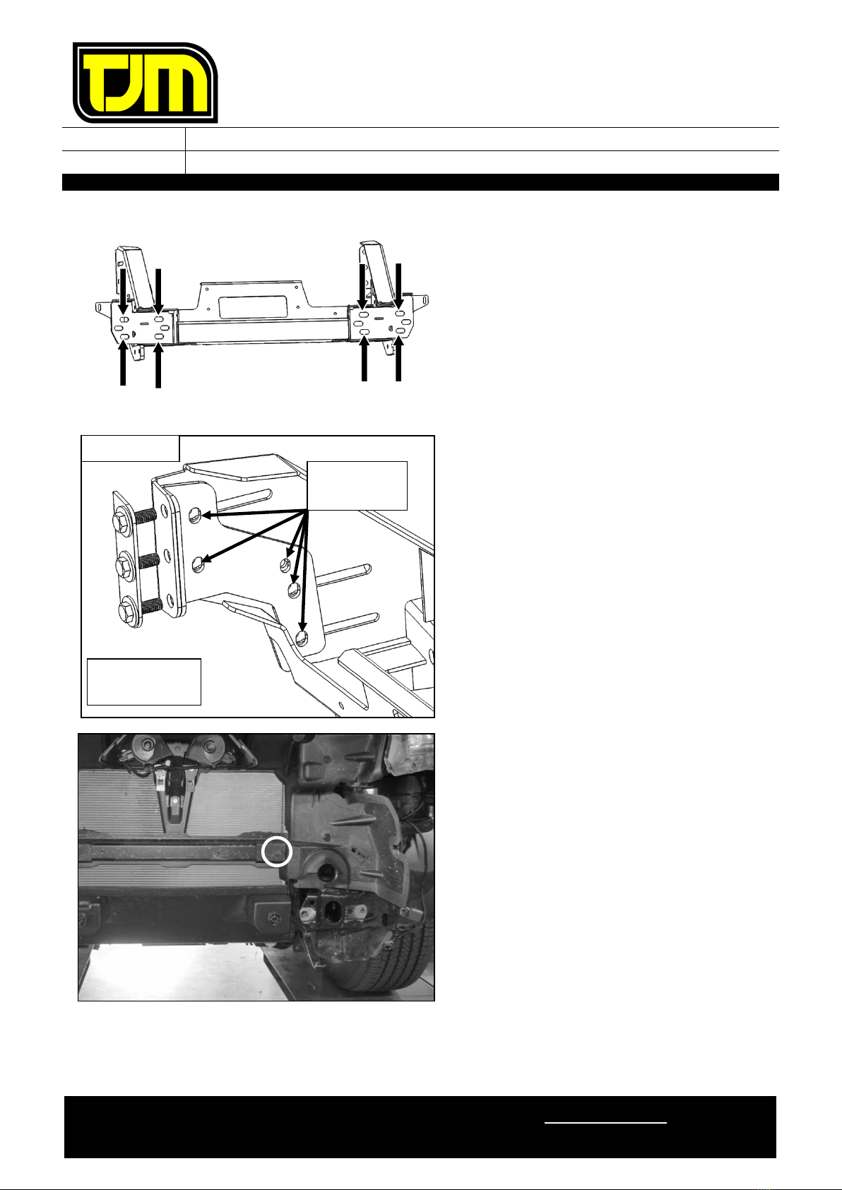
45. Position the chassis mount / winch frame and
winch frame washer plate on the vehicle chassis
rail ends then loosely secure it in place using
the fasteners retained in step 25.2.
THE CHASSIS MOUNT / WINCH FRAME
SHOULD FIT AROUND THE PREVIOUSLY
TRIMMED AIR GUIDES.
46. Centralize the chassis mount / winch frame to
the vehicle by measuring diagonally from mount
tip to headlamp corner as shown, equalize sizes
as close as practical.
47. Tighten bolts from step 45 to relevant torque
settings listed on page 2.
48. Using spacers (4mm) and (2mm) supplied, align
faces between chassis, chassis mount and
chassis support bracket, assemble loosely.
48.1. Using M12 x 1.25 x 90mm hex bolts (1),
M12 nyloc nuts (1) & 1/2” x Ø1-1/4” flat
washers (2) fasten loosely in place.
48.2. Using M12 x 1.25 x 50mm hex bolts (2),
M12 nyloc nuts (2) & 1/2” x Ø1-1/4” flat
washers (4) fasten loosely in place.
REPEAT ON LHS.
RHS SHOWN
CHASSIS RAIL END
RHS SHOWN
SPACERS
STEP 48.2
STEP 48.1
WASHER PLATE
FITTING INSTRUCTIONS
Product:
T15 Signature Frontal Protection System
Vehicle:
Ford Everest
Part No.
070AP15N20A
For product warranty, please refer to our website, www.tjm.com.au
F-11968.docx
Page 16 of 28
25/10/2022
49. Secure chassis mount / winch frame to the
vehicle through the holes shown using M10 x
1.25 x 30mm hex screws (8), M10 x Ø30mm
flat washers (16) & M10 nyloc nuts (8)
50. Tighten all fasteners installed in steps 48 and
49 to the relevant torque settings listed on
Page 2.
51. Fit clamp Angle bracket to inboard face of
winch frame and washer plate to front using
M12 x 1.25 x 35mm bolts (3), 1/2”x Ø1-1/4”
Flat Washers (6) & M12 nyloc nuts (3).
IMPORTANT –FIT M12 BOLT ASSEMBLY WITH
BOLT HEAD ON FRONT FACE.
52. Align plate with existing holes and tighten to
specified torque. Check holes and slots align
after tightening to allow easy bolt
fitment/clearance.
REPEAT ON LHS.
53. Remove and retain the indicated bolt from the
vehicle’s air guide.
54. Fix the fuse box vent bracket (F-9896) to the
indicated position using the previously retained
OE fastener.
NUTS
TO INSIDE!
RHS SHOWN
Holes must
align

FITTING INSTRUCTIONS
Product:
T15 Signature Frontal Protection System
Vehicle:
Ford Everest
Part No.
070AP15N20A
For product warranty, please refer to our website, www.tjm.com.au
F-11968.docx
Page 17 of 28
25/10/2022
55. Attach the supplied corrugated hose to the cut
end of the pipe removed in step 31. Secure
with a supplied cable tie, as shown opposite.
56. Feed the vent assembly between the cut air
guide and rear of the winch frame, as shown
opposite.
57. Secure the vent assembly to the bracket
installed in step 54 using a supplied cable tie.
58. Secure the corrugated hose to the air guide
with a cable tie through the temperature sensor
hole, as shown below.
59. Slide the free end of the corrugated hose onto
the fuse box receiver, as shown opposite.
FITTING INSTRUCTIONS
Product:
T15 Signature Frontal Protection System
Vehicle:
Ford Everest
Part No.
070AP15N20A
For product warranty, please refer to our website, www.tjm.com.au
F-11968.docx
Page 18 of 28
25/10/2022
60. Remove & discard the inner guard lower
bumper mount. Retain fasteners.
STEPS 61 TO 65 RHS ONLY
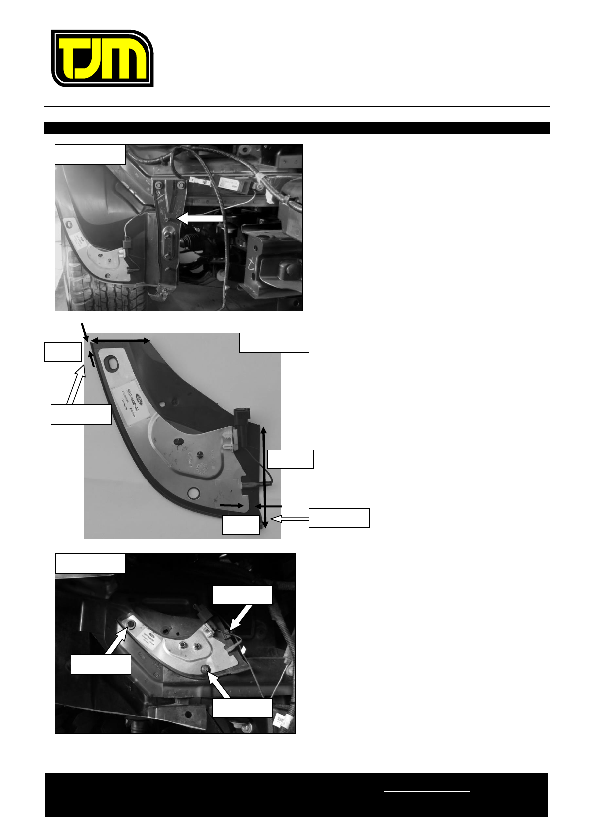
61. Mark and trim area around aerial:
61.1. Measure 5 mm up from aerial top edge 60
mm in from outside edge.
61.2. Measure 5 mm out from aerial side edge
and 100 mm up from bottom edge.
61.3. Join the two marked lines and trim
62. Deburr all edges.
63. Using a supplied M6 x Ø18mm flat washer (1)
and Christmas tree plug, secure the upper
corner of the aerial to the vehicle body as
shown.
64. Move wiring clip from radiator support panel to
the edge of the antenna where shown, connect
aerial
65. Insert the supplied grommet through the
antenna hole at the location shown. Secure to
the vehicle with an OE fastener retained from
step 60.
RHS SHOWN
RHS ONLY
STEP 61.2
STEP 61.1
60mm
5mm
15mm
100mm
STEP 64
STEP 63
64
RHS ONLY
STEP 65
FITTING INSTRUCTIONS
Product:
T15 Signature Frontal Protection System
Vehicle:
Ford Everest
Part No.
070AP15N20A
For product warranty, please refer to our website, www.tjm.com.au
F-11968.docx
Page 19 of 28
25/10/2022
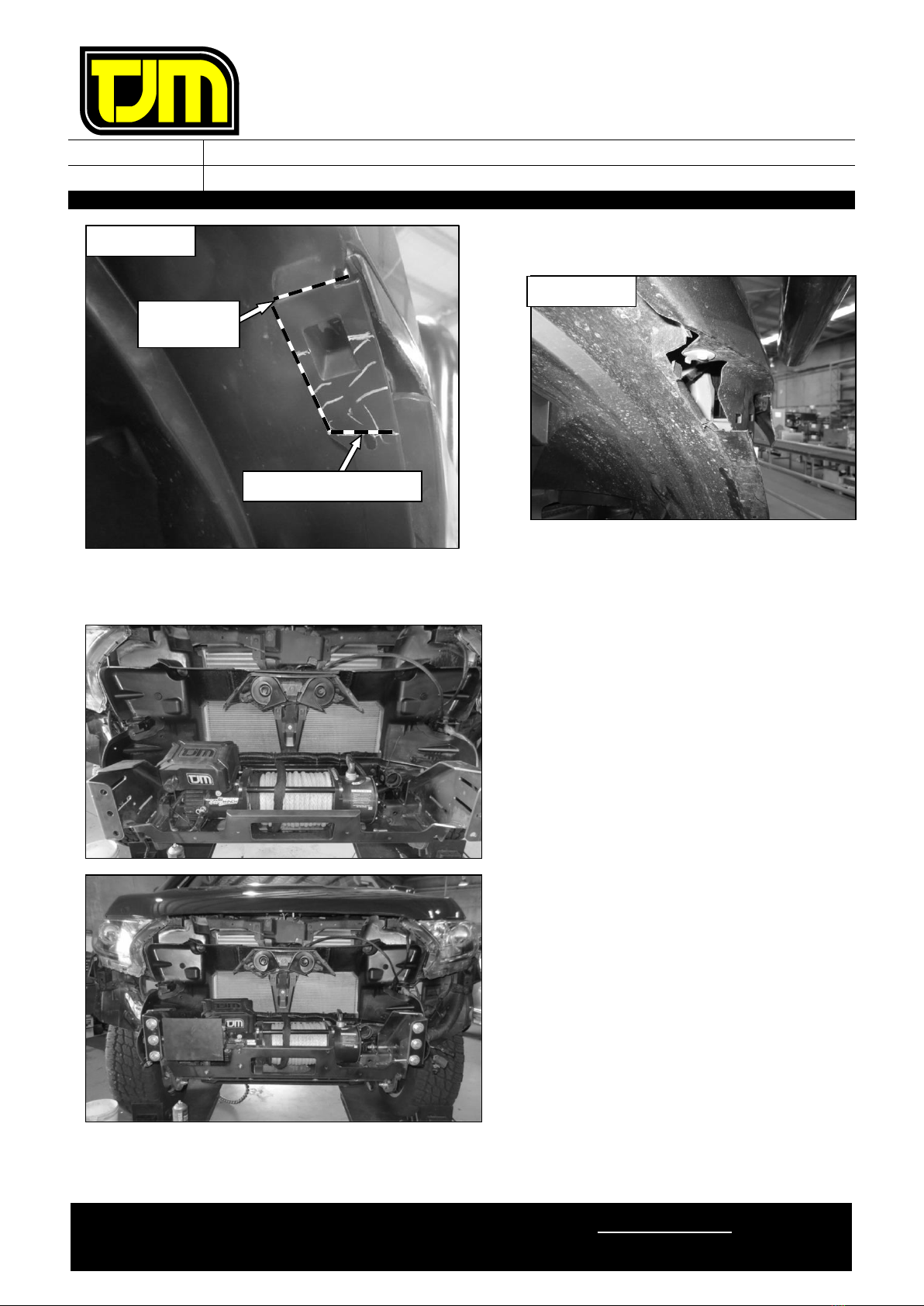
66. Mark and trim clearance relief cut on inner
guard aligning to features shown.
Steps 67 to 69 only apply if a winch is to be fitted.
Otherwise proceed to step 70.
67. Refer to the winch fitting instructions to fit the
winch to the chassis mount / winch frame.
DO NOT INSTALL WINCH FASTENERS AT
THIS TIME.
Steps 68 to 69 only apply for vehicles
fitted with radar, otherwise proceed to
step 70.
68. If radar was removed at step 25.1 install
mount bracket from kit 076SKITB20A as per
supplied instructions.
69. Fit winch control extension kit 946TQEXT500
as per supplied instruction.
RHS SHOWN
AS TRIMMED
ALONG TOP OF SLOT
ALONG
EDGE

FITTING INSTRUCTIONS
Product:
T15 Signature Frontal Protection System
Vehicle:
Ford Everest
Part No.
070AP15N20A
For product warranty, please refer to our website, www.tjm.com.au
F-11968.docx
Page 20 of 28
25/10/2022
A number of positions exist for mounting the winch control extension bracket
70. Cut the bumper along the cut lines marked in
steps 3to 5, discarding the lower portion.
71. Refit bumper and air intake to vehicle, using
OE fasteners retained.
72. Refit grille using OE fasteners retained.
73. Tighten the fasteners installed in step 30.
74. Fit the supplied pinchweld to the indicated
edge of the bumper.
75. Insert the nylon plugs supplied, into the
square cut-outs for the indicator/park lights
(as shown).
76. Separate the indicator / park light body from
the backing plate.
77. Secure the backing plate to the FPS, using the
screws provided with the light assemblies.
78. Supporting the backing plate, re-fit (clip) each
indicator / park light body (ensuring that an
adequate seal is achieved).
ENSURE THAT THE PARK LIGHT IS
TOWARDS THE OUTSIDE OF THE
VEHICLE.
79. Repeat the previous four steps for the
opposite side of the vehicle.
Other manuals for T15
3
This manual suits for next models
1
Table of contents
Other TJM Automobile Accessories manuals


Popular Automobile Accessories manuals by other brands

EUFAB
EUFAB 11514 operating instructions

AMP Research
AMP Research BedStep 75326-01A Application

APE OFFROAD
APE OFFROAD AC-PRO-SDK01 Instructions for Installation and Care

Tommy Gate
Tommy Gate 650 Series Mounting instructions

EZTRUNK
EZTRUNK EZLOCK installation instructions

Prorack
Prorack K464 Fitting instructions


Component Solution Services
Component Solution Services Verity S Series manual

Philips
Philips PV7002I Specifications

KMS
KMS IB/IA23 manual

APS Auto Parts Specialist
APS Auto Parts Specialist IA04SIA2B installation instructions

attica
attica ATTFB01C102-BX installation manual

watt & co
watt & co CARWATT user manual