manuals.online logo
Brands
  1. Home
  2. •
  3. Brands
  4. •
  5. TOPP
  6. •
  7. Controllers
  8. •
  9. TOPP C260 Product manual

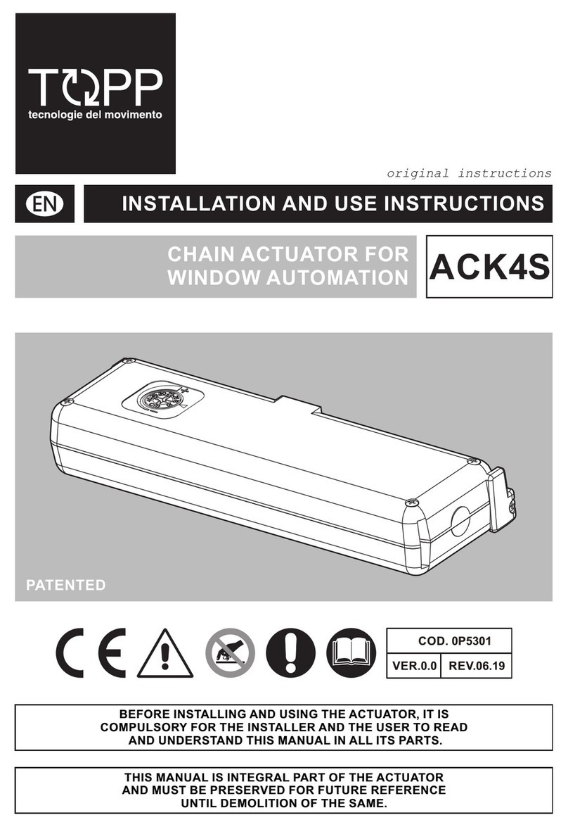
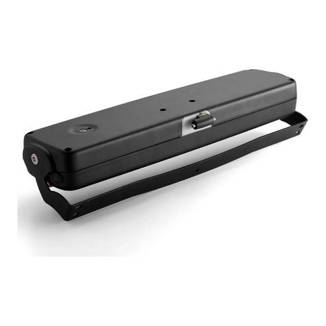
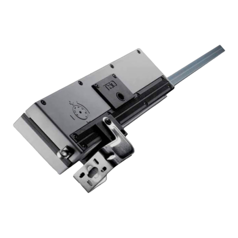
TOPP C260 Product manual

C260
COD. 0P5371
VER. 00 REV.07.20
INSTALLATION AND USE INSTRUCTIONS
CHAIN ACTUATOR FOR
WINDOW AUTOMATION
EN
BEFORE INSTALLING AND USING THE ACTUATOR, IT IS
COMPULSORY FOR THE INSTALLER AND THE USER TO READ
AND UNDERSTAND THIS MANUAL IN ALL ITS PARTS.
THIS MANUAL IS INTEGRAL PART OF THE ACTUATOR
AND MUST BE PRESERVED FOR FUTURE REFERENCE
UNTIL DEMOLITION OF THE SAME.
C260
INSTALLATION AND USE INSTRUCTIONS 3
EC DECLARATION
OF INCORPORATION PAG 4
GENERAL REMARKS AND SAFETY
WARNINGS PAG 5
TECHNICAL DESCRIPTION
TECHNICAL DATA PAG 7
COMPONENTS
PAG 9
APPLICATIONS
PAG 11
TOP HUNG outward opening
application PAG 14
BOTTOM HUNG outward opening
application PAG 16
BOTTOM HUNG inward opening
application PAG 18
VERTICAL outward opening application
PAG 20
ACTUATOR ON LEAF inward opening
application PAG 22
SIDE HUNG Outward opening
PAG 24
SIDE HUNG
Inward open PAG 27
ELECTRICAL CONNECTIONS
PAG 30
INDEX
INSTALLATION AND USE INSTRUCTIONS
4
C260
EC DECLARATION OF INCORPORATION
C260 GENERAL REMARKS AND SAFETY -2
INSTALLATION AND USE INSTRUCTIONS 5
GENERAL INSTRUCTIONS
• Before installing and using the actuator, it is compulsory that the installer and the user carefully read and understand this manual in
all its parts.
• This manual is integral part of the actuator and must compulsorily be preserved for future reference.
• The manufacturer has no liability for any eventual damage to persons, animals and things due to the inobservance of the prescrip-
tions described in this manual.
• In order for the automation unit to operate correctly, we recommend carrying out periodical maintenance on it, as indicated in this
manual.
• The warranty on the actuator will not be honored if product is not installed and used according to the instructions provided and the
regulations shown in this instruction manual and if it is used with non genuine parts, accessories, spare parts and/or control/feeding
units.
INSTALLER AND USER
• The actuator installation can be performed exclusively by competent and qualifi ed technical personnel satisfying the professional
and technical requirements foreseen by the laws in force in the country of installation.
• The installation technician shall accept full responsibility for any installation errors and for any failure to adhere to the instructions
provided in this manual. The installation technician shall therefore be exclusively liable for any damages caused to users and/or third
parties that may arise as a result of incorrect installation.
• The actuator can be used exclusively by a user acting in compliance with the instructions contained in this manual and/or in the
manual of the actuator control device (e.g.: control unit).
TECHNICAL ASSISTANCE
• Contact the installation technician or retailer for assistance.
RESERVED RIGHTS
• The reserved rights on this manual “Installation and use instructions” remain property of the Manufacturer.
• Each information herein contained (text, drawings, diagrams, etc.) is reserved.
• None part of this manual can be reproduced and disclosed (totally or partially) by any reproduction means (photocopies, microfi lms
or other) without written authorization of the Manufacturer.
DESCRIPTION OF PERSONNEL
USERS MUST NEVER PERFORM OPERATIONS RESERVED FOR MAINTENANCE PEOPLE OR SPECIALISED TECHNI-
CIANS. THE MANUFACTURER DECLINES ALL LIABILITY FOR DAMAGE DERIVING FROM FAILURE TO OBSERVE THE
ABOVE REQUIREMENTS.
Specialised electrician:
A specialised electrician must be able to install the actuator, start it and operate it both in normal conditions and in the maintenance mode;
he/she is qualifi ed to perform all electrical and mechanical adjustment and maintenance operations. He/she is allowed to work on live
electrical cabinets and junction boxes.
User:
specialised person capable of operating the actuator under normal conditions by using the relative controls. He/she must also be able to
operate with the actuator under “maintenance” in order to perform simple routine maintenance operations (cleaning), and start or reset
the actuator following an unscheduled stop
SAFETY GENERAL INSTRUCTIONS
• Operators must be informed of accident risks, safety devices and the general accident prevention regulations established by in-
ternational directives and by the law in force in the country of use. All operators must strictly comply with the accident prevention
regulations in force in the country of use.
• Do not remove or alter the plates placed on the actuator by the manufacturer.
• If the window frame is accessible from or installed at a height of less than 2.5 m from the ground, and if it can be commanded by
an untrained user or with a remote control device, fi t an emergency stop system which automatically cuts in to prevent the risk of
crushing or dragging parts of the body inserted between the moving and fi xed parts of the window frame.
• Do not operate dome windows in the presence of a load of snow in excess of the quantity declared acceptable by the window man-
ufacturer.
• Any tampering with or unauthorized replacement of one or more parts or components of the actuator, or the use of unoriginal acces-
sories and consumables, may increase the risk of accident and thus relieves the manufacturer of all civil and penal liability.
• The maintenance operations involving the total or partial dismounting of the actuator may only be performed after disconnecting it
from the power supply.
• This appliance may not be used by persons (children included) with reduced physical, sensorial or mental capacities, or inexpert
people, unless they are supervised and taught how to use it by a person responsible for their safety.
• Children must be controlled to make sure they do not play with the appliance.
• During handling and installation of the parts, the personnel shall be equipped with suitable personal protection equipment (PPE) so
as to perform the works required under safe conditions.
SAFETY DEVICES - PROTECTION AGAINST ELECTRIC HAZARD
• The actuator is protected against electric hazard due to direct and indirect contacts.
• The protection measures against direct contacts aim at protecting people against hazards due to contact with active parts, usually
live parts; while the protection measures against indirect contacts aim at protecting people against hazards due to conducing part,
which are usually insulated, but could become live in case of failure (insulation failure).
The adopted protection measures are the following:
1) Insulation of live parts by means of a plastic material body;
2) Enclosure with suitable protection degree;
3)C260 equipped with double insulation: Protection of passive type given by the use of components with double insulation, also called
components of class II or with equivalent insulation. (It is forbidden to connect the actuators equipped with double insulation to the earth
plant.
INSTALLATION AND USE INSTRUCTIONS
6
2- GENERAL REMARKS AND SAFETY C260
SAFETY PLATES
• It is forbidden to remove, move, spoil or in anyway reduce the visibility of the safety plates. Failure to observe the above may cause
serious harm to people and damage to property. The manufacturer declines all liability for any damage caused by the failure to
observe the above requirement.
• In Figure illustrates the safety plate: this must applied directly to the outside of the actuator or near it and always in a position where
it can be seen by the installer and/or operator.
RESIDUAL RISKS
The installer and the user are herewith informed that after the actuator has been installed on the window, the actuator drive can acciden-
tally generate the following residual risk:
• Residual risk: Hazard of squashing or dragging of body parts inserted between the movable and the fi x part of the window frame.
• Exposure frequency: Accidental and when the installer or the user decides to perform a wrong voluntary action.
• Severity of the damage: Light lesions (usually reversible)
• Adopted measures: Before enabling the device, it is compulsory to verify that near the window there are not persons, animals or
things whose safety may be accidentally jeopardized. During actuator operation, it is compulsory to be in a safe control position
assuring visual control on the window movement.
SPARE PARTS AND ACCESSORIES UPON REQUEST
• The use of “non-original” spare parts and accessories which may endanger the safety and the effi ciency of the actuator is forbidden.
• Original spare parts and accessories have to be requested exclusively to your dealer or to the manufacturer stating type, model,
serial number, and year of construction of the actuator.
• In case of replacement of the power supply cable, it is necessary to use a cable type h05-vvf 3 x 0.75 .
• The replacement can be performed exclusively by competent and qualifi ed technical personnel meeting the professional and tech-
nical requirements foreseen by the laws in force in the country of installation.
MAINTENANCE
• If the actuator works incorrectly, contact the manufacturer.
• Any work on the actuator (e.g.: power cable, etc.) or its components may only be carried out by personnel qualifi ed by the manufac-
turer. Topp declines all liability for work performed by unauthorised people.
• The maintenance operations involving the total or partial dismounting of the actuator may only be performed after disconnecting it
from the power supply. The actuator incorporates components that do not require signifi cant routine or extraordinary maintenance
operations.
The recommended maintenance activities should in any case involve the periodical execution (every 6 mounths) of at least the following
operations: that the actuator assembly components are clean, the replacement of components that show signs of superfi cial damage
such as injuries, cracks, discoloration, etc., the fi xing systems (brackets and screws) are tight, the window frame is not deformed and the
seals are tight, and check the cables and connectors.
This maintenance activity may be carried out either by TOPP, in accordance with a specifi c agreement made with the user, or by the
installation technician or by other competent and qualifi ed technical personnel in possession of all legal requirements.
DEMOLITION
• The demolition of the actuator must occur in compliance with the laws in force on environment protection.
• Diff erentiate the parts making up the actuator according to their diff erent material type (plastic, aluminum, etc.).
C260 GENERAL REMARKS AND SAFETY -2
INSTALLATION AND USE INSTRUCTIONS 7
TECHNICAL DATA
C260
MODEL C260/230V
Power supply voltage 230V ~ 50Hz
Absorbed current 0,4 A
Absorbed power with load 80 W
Thrust force 600 N
Tractive force 600 N
Idle translation speed 13 mm/s
Duration of the idle stroke (2) 46 s
Protection against electric shock Class II
Actuator length 1500 ÷ 4000 mm
Protection degree of electric devices IP30
Type of service S2 (1) 4 min
Parallel electric connection of more actuators on different windows Yes
Operating temperature -5°C ÷ +50°C
Limit switch: Electronic for opening - by amperometric absorption for closing.
Actuator weight with brackets 4,9Kg - 8 Kg
Operation stroke(2) 600mm
USE OF THE ACTUATOR
• The actuator can be used exclusively by an user acting in compliance with the instructions contained in this manual and/or in the
manual of the actuator control device (e.g.: wind and rain control unit).
• Before using the actuator, it is compulsory for the user to read and understand in all its parts this manual, as well as the eventual
manual of the installed control device type.
• Before operating the actuator, the user must compulsorily verify that near and/or under the window there are not any person, animal
and thing whose safety may be accidentally jeopardized.
• During the operation of the actuator control device, the user has to compulsory occupy a safe control position assuring visual control
on the window movement.
• It is compulsory to verify constantly in time the functional effi ciency and the rated performance of the actuator, of the window frame
where it is installed and of the electric plant, performing when necessary interventions of routine or supplementary maintenance
assuring operation conditions complying with safety regulations.
• l above mentioned interventions can be performed only by competent and qualifi ed technical personnel meeting the professional
and technical requirements foreseen by the law in force in the country of installation.
• In order for the automation unit to operate correctly, we recommend carrying out periodical maintenance on it, as indicated in this
manual.
• Topp informs the user that, in accordance with art. 8 of ministerial decree no. 38 of 22.1.2008, the owner of the system is responsible
for adopting all necessary measures to maintain the safety features set out in applicable legislation, observing the instructions for
maintenance and use provided by the manufacturer of the device and by the company that carried out the installation.
• The use of the actuator allows to control automatically the opening and closing of the window according to the type of control device
installed.
TECHNICAL DESCRIPTION -3
(1) Service of limited duration according to EN 60034
(2) Tolerance on the precision of limit switch tripping at output: +/- 10mm
INSTALLATION AND USE INSTRUCTIONS
8
3- TECHNICAL DESCRIPTION C260
FORMULAS FOR THE CALCULATION OF THRUST AND TRACTIVE FORCE
DESTINATION OF USE
• The actuator has been designed and manufactured to perform, by means of a command device, the opening and closing of top
hinged windows, bottom hinged windows, vertical and side hinged windows.
USE LIMITS
• The actuator has been designed and manufactured exclusively for the destination of use given in the previous paragraph, therefore,
any other type of use is strictly forbidden in order to assure in any moment the safety of the installer and of the user, as well as the
effi ciency of the actuator itself.
• Check carefully all environmental conditions (temperature, humidity, wind, snow, potential chemical agents, etc.) and installation
settings (misaligned fi tting of brackets and attachment to the frame, frictions produced by hinges or gaskets, use of selfbalancing
window stays, etc.) it is recommended that they not exceed the actuator performances shown in the technical data table. If they do,
please fi nd an alternative and more suitable product for your application.
• It is strictly forbidden to install the actuator on the external side of the window frame subject to atmospheric agents (rain, snow, etc.).
• The use of the actuator in environments with potentially explosive atmosphere is strictly forbidden.
• It is compulsory to keep the package and the actuator out of reach of children.
RATING PLATE AND “CE” MARKING
The “CE” marking certifi es the compliance of the machine with the essential safety and health requirements foreseen by the product
European Directives.
The rating plate is an adhesive plate in polyester, silk-screen printed in black, having the following size: L=24 mm - H=60 mm
It is applied externally on the actuator. The plate bears in readable and indelible way the following data:
• logo and address of the manufacturer
• type and model
• voltage and intensity of power supply (V - A)
• absorbed electric power P (W)
• thrust and tractive force F (N)type of service S2 (min)
• idle translation speed (mm/s)
• protection degree (IP)
• “CE” marking
• symbol of WEEE Directive 2002/96/CE
• serial number
STANDARDS, LAWS, CODES AND REGULATIONS
• The latest versions of the common and country specifi c standards, laws, codes and regulations have to be observed.
PACKAGE
Each package of the product contains:
1) Actuator equipped with power supply (Ref. A);
2) Window mounting brackets (depending on application) and screws for aluminum (Ref. B);
3) Actuator brackets (depending on application) and screws for aluminum (Ref. C);
4) Installation and use instructions (Ref.D);
5) Safety plate (Ref. E).
• Make sure that the above described components are contained in the package, as well as that the actuator has not been damaged
during transport.
• Should any anomaly be detected, it is forbidden to install the actuator, and it is compulsory to require technical assistance from your
dealer or the manufacturer.
• The packaging (paper, plastic, etc.) Has to be disposed according to the laws in force.
C260 TECHNICAL DESCRIPTION -3
INSTALLATION AND USE INSTRUCTIONS 9
COMPONENTS
A
B
C
DE
INSTALLATION AND USE INSTRUCTIONS
10
3- TECHNICAL DESCRIPTION C260
COMPONENTS DIMENSIONING
C260 TECHNICAL DESCRIPTION -3
INSTALLATION AND USE INSTRUCTIONS 11
Applications Window Brackets H (mm)(*)
ACTUATOR MOUNTING
ON THE FRAM
TOP HUNG
outward
opening
application
S2
SD
M1
600
BOTTOM HUNG
outward
opening
application
S2
SF
M1 600
BOTTOM HUNG
inward
opening
application
S3
SG
M2 1000
VERTICAL
outward
opening
application
S4
SH
M1 800
SIDE HUNG
outward
opening
application
LEFT
S2
SF
PF
M1
600
SIDE HUNG
outward ope-
ning
application
RIGHT
S4
SF
PF
M1
600
SIDE HUNG
inward
opening
application
LEFT
S3
SF
LF
M2
1000
SIDE HUNG
inward
opening
application
RIGHT
S3
SF
PF
M2
1000
ON LEAF
On the window
inward opening
application
S4
SD
M1 950
(*) Distance from the opening edge of the window to the axis of rotation of the window.
INSTALLATION AND USE INSTRUCTIONS
12
4- INSTALLATION C260
GENERAL INSTRUCTIONSI
• L’installazione dell’attuatore deve essere eseguita esclusivamente da personale tecnico competente e qualifi cato in possesso de
• The actuator installation can be performed exclusively by competent and qualifi ed technical personnel satisfying the professional
and technical requirements fore seen by the laws in force in the country of installation.
• The actuator performance must be suffi cient to assure the correct movement of the window. It is compulsory to verify the thrust or
tractive force according to the type and weight of the window. It is forbidden to exceed the limits concerning technical data (cap 3).
• The actuator installation must be performed exclusively with closed window.
• Before performing the installation of the actuator on bottom hung windows, verify that on both sides of the window two compass
stroke limit devices are installed in order to avoid the accidental fall of the window.
• For correct operation of the actuator, the window frame must have a minimum height value included in the range stated in par 3.
• Verify that distance “D” between the actuator shell and the chain end is greater than 5 mm.
• The fi tting surface for the brackets must be perfectly fl at and/or smooth.
• Check the adequacy of the window and the suitability of the materials of the window and/or frame on which the actuator will be fas-
tened. And it must ensure a good support of the actuator-window assembly during the movement.
INSTALLATION
• Perform the installation as described in Chapter 5 : INSTALLATION INSTRUCTIONS / FIGURES.
ELECTRIC CONNECTIONS
• The electric connection of the actuator (Cap.6) can be performed only by competent and qualifi ed technical personnel foreseen by
the law in force in the country of installation who can issue to the customer a declaration of conformity for the connection and/or
plant carried out.
• Before performing the electric connection of the actuator, verify the correct installation on the window
• The mains to which the actuator is connected must comply with the requirements of the laws in force in the country of installation,
as well as satisfy the technical features given in Cap.3 and on the rating plate and the “CE” marking.
• The section of the mains cables must be properly sized according to the absorbed electric power (see rating plate and “CE” marking).
• Any type of electric material (plug, cable, terminals, etc.) Used for the connection must be suitable for the use, with “CE” marking,
and complying with the requirements foreseen by the laws in force in the country of installation.
• To assure an effi cient separation from the mains, it is compulsory to install upstream of the device a temporary bipolar switch (push-
button) of approved type. Upstream of the command line, it is compulsory to install an unipolar main switch with opening of contacts
of at least 3 mm.
• Before making any electrical connections on the actuator, make sure the power supply cable is not damaged. If the cable is dam-
aged, then it must be replaced by the manufacturer through the technical assistance service or by technical operators.
ELECTRIC CONNECTIONS DEVICES
THE CONTROL DEVICES USED TO DRIVE THE ACTUATOR MUST ASSURE THE SAFETY CONDITIONS FORESEEN BY
THE LAWS IN FORCE IN THE COUNTRY OF USE.
According to the diff erent type of installations, the actuators can be driven by the following control devices:
1) MANUAL PUSH-BUTTON:
Bipolar switch button with central OFF position, with biased-off switch;
2) OPTIONAL: CONTROL AND FEEDING UNIT:
TOPP microprocessor control units (e.g.: Mod. TF, etc.) controlling the single actuator or more than one actuator simultaneously by
means of one or more manual pushbuttons, an infrared remote control or a 433 Mhz radio control. To these control units, it is possible to
connect rain sensors (RDC - 12V), wind sensor (RW) and brightness sensor.
• To assure a correct operation of the actuator, the command and feeding units eventually used have to provide power
supply to the actuator for max. 120 sec.
• Before operating the actuator, the user must compulsorily verify that near and/or under the window there are not any
person, animal and thing whose safety may be accidentally jeopardised
CORRECT ASSEMBLY OF THE ACTUATOR
• The correct adjustment of the window frame closing assures the life and the tightness of the seals, as well as the good operation of
the actuator.
• With open window frame, verify that the stroke is some centimetre lower than the stroke limited by window frame mechanical limit
devices;
• Verify that the chain coupling (A) is on the same axis of the chain end (B). Otherwise, loosen the tightening screws and position
correctly. When the devices are not coaxial, damages to the actuator and the window frame may arise.
C260 INSTALLATION -4
INSTALLATION AND USE INSTRUCTIONS 13
MANUAL RELEASE OF THE ACTUATOR
BEFORE PERFORMING ANY TYPE OF TRIPPING ON THE ACTUATOR AND ON THE WINDOW, IT IS COMPULSORY TO
DISCONNECT THE POWER SUPPLY OF THE ACTUATOR AND TO PUT ON “0” THE EVENTUAL SWITCHES OF THE CON-
TROL DEVICES.
IT IS COMPULSORY TO PADLOCK THE MAIN SWITCH OF THE DISCONNECTION DEVICE INSTALLED ON THE MAINS IN
ORDER TO AVOID ANY UNEXPECTED START. IF THE MAIN SWITCH CANNOT BE PADLOCKED, IT IS COMPULSORY TO
PLACE A SIGN FORBIDDING THE ENABLING.
If it is necessary to operate the window manually, to close it, open it, in the absence of electricity or if the mechanism is blocked, follow
the installation instructions in reverse order:
• Release the actuator (terminals M1-M2) from the bracket.
• Release the end of the chain,
S2-S4: unscrew both screws (Ref. 1.2) with a 2.5mm hexagon wrench, move the bracket and remove the end of the chain from
the shorter pin side.
S3- Bottom hung – inward opening: with a 3 mm Allen key and 7 mm hex wrench unscrew the nut, remove the pin until the chain
end is released.
RESTORATION OF THE STROKE
The Smart Reset System is integrated into the software of the electronic control board of actuator. This system adjusts the closure of
the window in a highly effi cient fashion so as not to damage the window in any way. If you were to put an obstacle in the way while the
window is closing, the system would block the actuator(s) attached to the window to avoid damaging it. If this happens in the last 50mm
of the movement, which is below the allowable maximum overlap, you might fi nd that the window remains slightly open the next time it
is closed. You only need to briefl y open and close the window a few times (about 4times) to activate the system and restore the window
to its correct and proper closure.
Detailed description for restoration of the stroke:
Once the mechanical fi nal stroke has been adjusted and the installation is completed, the actuator does not need further adjustment.
If an obstacle is detected, more than 3 times consecutively in the same position, it will be recognized as a fi nal stroke (in opening or closing)
and therefore, at subsequent openings, the stroke will be automatically reduced to the obstacle even if this is removed.
The original fi nal stroke is restored automatically, as the actuator checks the limit switches every 4 cycles. If the obstacle has been remo-
ved, on the fi fth cycle, the machine will continue its run for a maximum of 50mm beyond the previous acquired position.
If the obstacle had limited the stroke by more than 50mm, you will have to wait for the next 4 cycles to repeat the limit switch check and
to continue the run for a further 50mm.
To restore the fi nal stroke manually it will be suffi cient (once the obstacle is removed) to position the machine near the original fi nal stroke
and activate the manual command in open-close for 4 cycles (it is not necessary to complete the whole cycle but it is suffi cient to give the
command for 1s in open and 1s in close). In this way, every 4 cycles the stroke will be increased by 50mm.
INSTALLATION AND USE INSTRUCTIONS
14
5- INSTALLATION INSTRUCTIONS / FIGURE C260
Stroke 600
230V
Standard
TOP HUNG
outward opening application
Double push point
C260 INSTALLATION INSTRUCTIONS / FIGURES -5
INSTALLATION AND USE INSTRUCTIONS 15
12
34
56
78
910
INSTALLATION- Open the package and remo-
ve the various components;
1)With a pencil draw the centre line X of the
window frame. Measure the distance D betwe-
en the two chain terminals of the actuator and
mark it on the window, symmetrically to the mi-
dline X marked previously, trace axis X1 and
X2;
2)Trace axis X1’ and X2’.
Taking as reference the axis X1,X1’ and
X2,X2’ previously traced, the hole layout for
the application and the components dimen-
sions, pag.10, mark the points for the holes to
fasten the brackets S2 and SD; with a suitable
drill, create on the window the holes;
3)4)5) Mount the two movable window brackets
S2 and the two frame brackets SD, with appro-
priate screws;
6)Insert the two pairs of clamps “M1“, fi tting
them in the actuator slider adjacent to the
chain terminal, then close them partially with
the screw and nut in the package; Position the
clamps 80mm on either side of the chain termi-
nal midline and tighten the screw all the way;
Perform the electric connections according to
the provisions as well as with reference to the
wiring diagram. Power the actuator and let the
chain come out for at least 250mm of stroke,
then disconnect the actuator;
7)8)First fasten the LEFT chain terminal to the
S2, fi rst fi t the long side of the shaft and then in-
sert the entire assembly. Move the square plate
to the centre of the mount and hand tighten bolt
A. Now insert bolt B (included) into the frame
mount and tighten both bolts down fully with a
2.5mm hex wrench (torque to 2,3 Nm).
Then fasten the RIGHT chain terminal to the
S2, as described upper.
9)Fasten the clamps M1 to the brackets for
connection to the window SD . Make sure the
brackets for connection to the window are cor-
rectly fastened to their clamps. The number of
clamps necessary for assembly will depend on
the length of the actuator: up to 3 meters only 2
clamps are needed, over 3 meters add a third
at the center of the actuator.
10) Connect the power actuator. Perform a test
of complete window frame opening and closing.
Verify that with open window frame, the stroke
is some centimetres lower than the stroke limi-
ted by window frame mechanical limit devices.
Once the closing phase is ended, verify that the
window frame is completely closed by checking
the seal defl ection.
INSTALLATION AND USE INSTRUCTIONS
16
5- INSTALLATION INSTRUCTIONS / FIGURE C260
Stroke 600
230V
Standard
BOTTOM HUNG
outward opening application
Double push point
C260 INSTALLATION INSTRUCTIONS / FIGURES -5
INSTALLATION AND USE INSTRUCTIONS 17
12
34
56
78
910
INSTALLATION
Open the package and remove the various
components;
1)With a pencil draw the centre line X of the
window frame. Measure the distance D betwe-
en the two chain terminals of the actuator and
mark it on the window, symmetrically to the mi-
dline X marked previously, trace axis X1 and
X2;
2)Trace axis X1’ and X2’.
Taking as reference the axis X1,X1’ and
X2,X2’ previously traced, the hole layout for
the application and the components dimen-
sions, pag.10, mark the points for the holes to
fasten the brackets S2 and SF; with a suitable
drill, create on the window the holes;
3)4)5) Mount the two movable window brackets
S2 and the two frame brackets SF, with appro-
priate screws;
6)Insert the two pairs of clamps “M1“, fi tting
them in the actuator slider adjacent to the
chain terminal, then close them partially with
the screw and nut in the package; Position
the clamps 80mm on either side of the chain
terminal midline and tighten the screw all the
way;Perform the electric connections accor-
ding to the provisions as well as with reference
to the wiring diagram. Power the actuator and
let the chain come out for at least 250mm of
stroke, then disconnect the actuator;
7)8)First fasten the RIGHT chain terminal to the
S2, fi rst fi t the long side of the shaft and then in-
sert the entire assembly. Move the square plate
to the centre of the mount and hand tighten bolt
A. Now insert bolt B (included) into the frame
mount and tighten both bolts down fully with a
2.5mm hex wrench (torque to 2,3 Nm). Then
fasten the LEFT chain terminal to the S2, as
described upper.
9)Fasten the clamps M1 to the brackets for
connection to the window SF . Make sure the
brackets for connection to the window are cor-
rectly fastened to their clamps. The number of
clamps necessary for assembly will depend on
the length of the actuator: up to 3 meters only 2
clamps are needed, over 3 meters add a third
at the center of the actuator.
10) Connect the actuator. Perform a test of
complete window frame opening and closing.
Verify that with open window frame, the stroke
is some centimetres lower than the stroke limi-
ted by window frame mechanical limit devices.
Once the closing phase is ended, verify that the
window frame is completely closed by checking
the seal defl ection.
INSTALLATION AND USE INSTRUCTIONS
18
5- INSTALLATION INSTRUCTIONS / FIGURE C260
Stroke 600
230V
Standard
BOTTOM HUNG
Inward opening
Double push point
C260 INSTALLATION INSTRUCTIONS / FIGURES -5
INSTALLATION AND USE INSTRUCTIONS 19
12
34
56
78
910
INSTALLATION
Open the package and remove the various com-
ponents;
1)With a pencil draw the centre line Y of the win-
dow frame. Measure he distance D between the
two chain terminals of the actuator and mark it on
the window, symmetrically to the midline Y mar-
ked previously, trace axis Y1 and Y2;
2)Taking as reference the axis Y1 and Y2 previou-
sly traced, the hole layout for the application and
the components dimensions, pag.10, mark the
points for the holes to fasten the brackets S3 and
SG;
With a suitable drill, create on the window the ho-
les;
3) 4) Mount the two movable window brackets S3
and the two frame brackets SG with appropriate
screws;
5)Close the two pairs of clamps M2 partially with
the screws and nut provided in the package;
6)Fit the two pairs of clamps previously assem-
bled M2 on the brackets SG (window frame);
WARNING: do not damage the swivel bracket
when fi tting the clamps; make sure that the
window brackets are correctly fastened to their
clamps.
7)Perform the electric connections according to
the wiring diagram. Power the actuator and let the
chain come out for at least 150mm of stroke, then
disconnect the actuator;
Fit the actuator into the clamps M2 through the
tracks on the actuator. Centre the chain-end on
the bottom-hinged bracket.
8) Fasten the chain terminal to the bottomhinged
Bracket S3 (wing) with the screw and nut provi-
ded in the package;
WARNING: tighten the nut up to the stop with the
bracket, not over as this may compromise the cor-
rect functioning of the actuator.
9) Check the correspondence of each chain ter-
minal S3 with the M2 terminal, then close fi rmly
the clamps M2;
The number of clamps necessary for assembly
will depend on the length of the actuator: up to 3
meters only 2 clamps are needed, over 3 meters
add a third at the center of the actuator.
10) ) Power the actuator. Perform a test of com-
plete window frame opening and closing. Verify
that with open window frame, the stroke is some
centimetres lower than the stroke limited by win-
dow frame mechanical limit devices. Once the
closing phase is ended, verify that the window
frame is completely closed by checking the seal
defl ection.
INSTALLATION AND USE INSTRUCTIONS
20
5- INSTALLATION INSTRUCTIONS / FIGUR C260
Stroke 600
230V
Standard
VERTICAL
outward opening application
Double push point

Other TOPP Controllers manuals

TOPP C30 Operating and maintenance manual

TOPP

TOPP C30 Operating and maintenance manual

TOPP C160RWA Operating and maintenance manual

TOPP

TOPP C160RWA Operating and maintenance manual

TOPP ACK4 Operating and maintenance manual

TOPP

TOPP ACK4 Operating and maintenance manual

TOPP C20 Operating and maintenance manual

TOPP

TOPP C20 Operating and maintenance manual

TOPP C25S Operating and maintenance manual

TOPP

TOPP C25S Operating and maintenance manual

TOPP T50 Operating and maintenance manual

TOPP

TOPP T50 Operating and maintenance manual

TOPP ACK4S Series Operating and maintenance manual

TOPP

TOPP ACK4S Series Operating and maintenance manual

TOPP C15 Series Operating and maintenance manual

TOPP

TOPP C15 Series Operating and maintenance manual

TOPP ELLISCO C40 Operating and maintenance manual

TOPP

TOPP ELLISCO C40 Operating and maintenance manual

TOPP C20 Operating and maintenance manual

TOPP

TOPP C20 Operating and maintenance manual

TOPP C240 Operating and maintenance manual

TOPP

TOPP C240 Operating and maintenance manual

TOPP TOPP Operating and maintenance manual

TOPP

TOPP TOPP Operating and maintenance manual

TOPP ACK4 Operating and maintenance manual

TOPP

TOPP ACK4 Operating and maintenance manual

TOPP S80 Series Operating and maintenance manual

TOPP

TOPP S80 Series Operating and maintenance manual

TOPP C130 Series Operating and maintenance manual

TOPP

TOPP C130 Series Operating and maintenance manual

TOPP T50 Operating and maintenance manual

TOPP

TOPP T50 Operating and maintenance manual

TOPP C40S User manual

TOPP

TOPP C40S User manual

TOPP C30S/230V User manual

TOPP

TOPP C30S/230V User manual

TOPP T80 Operating and maintenance manual

TOPP

TOPP T80 Operating and maintenance manual

TOPP C20 User manual

TOPP

TOPP C20 User manual

TOPP T50S Product manual

TOPP

TOPP T50S Product manual

TOPP ACK5 Product manual

TOPP

TOPP ACK5 Product manual

TOPP C25 Operating and maintenance manual

TOPP

TOPP C25 Operating and maintenance manual

Popular Controllers manuals by other brands

Magnimage MIG-CL9600 Series user manual

Magnimage

Magnimage MIG-CL9600 Series user manual

3M EX II 1710SC reference guide

3M

3M EX II 1710SC reference guide

Rain Bird WPX2 user manual

Rain Bird

Rain Bird WPX2 user manual

Actuonix LAC User configuration guide

Actuonix

Actuonix LAC User configuration guide

Sony PlayStation DualSense CFI-ZCT1G user manual

Sony

Sony PlayStation DualSense CFI-ZCT1G user manual

Pentair MYERS 19280C Instruction manual and parts list

Pentair

Pentair MYERS 19280C Instruction manual and parts list

Avonic CM-CON100 user manual

Avonic

Avonic CM-CON100 user manual

GESTRA NRR 2-60 Original Installation & Operating Manual

GESTRA

GESTRA NRR 2-60 Original Installation & Operating Manual

Mircom OpenBAS-LC-NX12R installation manual

Mircom

Mircom OpenBAS-LC-NX12R installation manual

Kramer PT-12 quick start guide

Kramer

Kramer PT-12 quick start guide

Leroy-Somer R 130 Installation and Maintenance

Leroy-Somer

Leroy-Somer R 130 Installation and Maintenance

Wirthco 23125 Installation & operation manual

Wirthco

Wirthco 23125 Installation & operation manual

Johnson Controls Hitachi C4IRK01 Operation manual

Johnson Controls

Johnson Controls Hitachi C4IRK01 Operation manual

Georges Renault CVIS II Operator's manual

Georges Renault

Georges Renault CVIS II Operator's manual

YASKAWA CIPR-GA50C series Technical manual

YASKAWA

YASKAWA CIPR-GA50C series Technical manual

Viconics VTR7300 Series installation guide

Viconics

Viconics VTR7300 Series installation guide

CNC4PC THC-1 user manual

CNC4PC

CNC4PC THC-1 user manual

Control Microsystems SCADAPack 350 Hardware manual

Control Microsystems

Control Microsystems SCADAPack 350 Hardware manual

manuals.online logo
manuals.online logoBrands
  • About & Mission
  • Contact us
  • Privacy Policy
  • Terms and Conditions

Copyright 2025 Manuals.Online. All Rights Reserved.