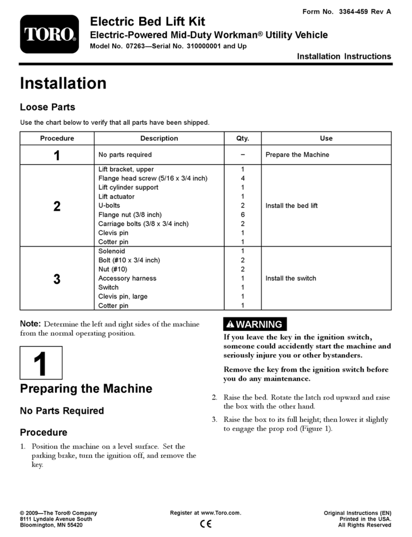
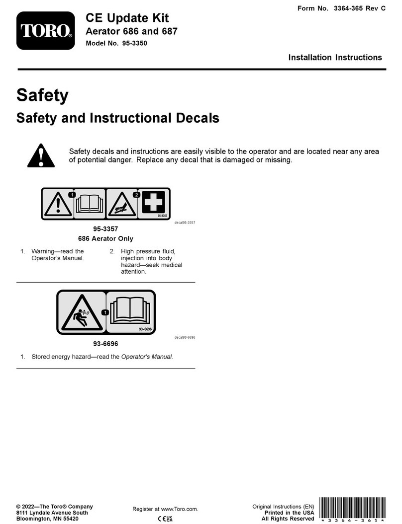
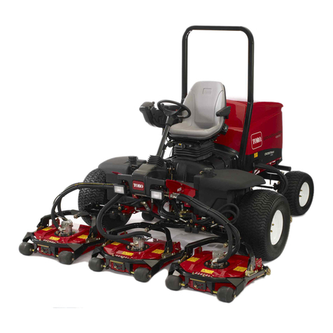
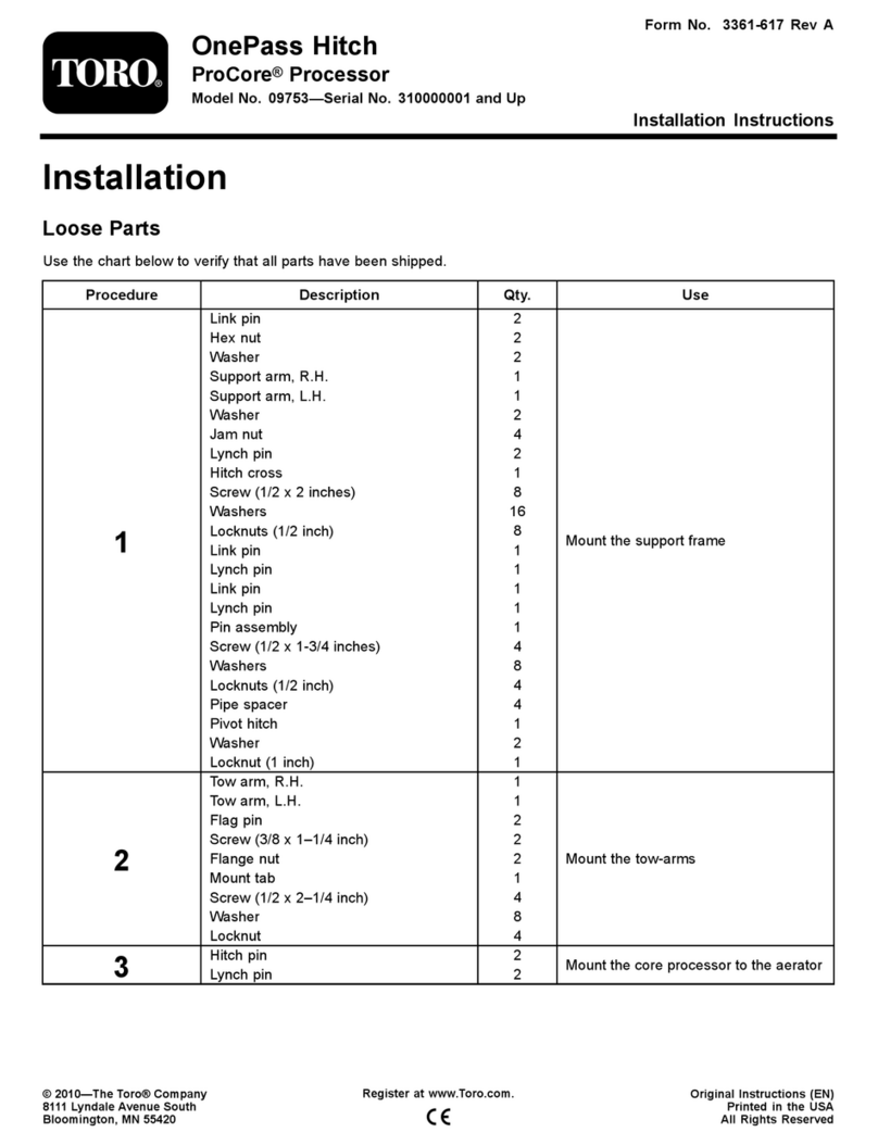
Toro 08731 User manual

FormNo.3372-400RevC
MidmountToolbarSystem
SandPro®/IneldPro®3040and5040TractionUnit
ModelNo.08731—SerialNo.312000001andUp
Operator'sManual
Important:Beforeinstallingthemid-mounttoolbarsystem,youshouldobtainoneofthetoolbarsavailableforuse
withthesystem.Formoreinformation,contactanAuthorizedToroDistributor.
Setup
LooseParts
Usethechartbelowtoverifythatallpartshavebeenshipped.
ProcedureDescriptionQty.Use
1Nopartsrequired–Dothepre-installationsetup.
Bolt(5/16x2-1/4inches)2
Nut(5/16inch)2
Scarierlift-handleassembly1
Bolt(1/2x3-1/4inches)2
Thinlocknut(1/2inch)2
Detentplate1
2
Knob1
Installthescarierlift-handleassembly.
Pivottube1
Extensionspring1
Springrod1
Pivottubebracket2
Bolt(3/8x3inches)4
Locknut(3/8inch)6
Springbracket1
3
Bolt(3/8x2-3/4inches)1
Installthepivottubeandthetension
spring.
Adjustablerodassembly1
Bolt(1/2x1-1/2inches)1
4Locknut(1/2inch)2
Installtheadjustablerodassembly.
Screenpanel1
Pan-headscrew(#10x1/2inch)2
Right-handsaddleassembly1
Left-handsaddleassembly1
Bolt(5/16x1inch)4
5
Locknut(5/16inch)4
Installthescreenpanelandsaddles.
6Toolbar(soldseparately)1Installatoolbar.
©2014—TheToro®Company
8111LyndaleAvenueSouth
Bloomington,MN55420
Registeratwww.T oro.com.OriginalInstructions(EN)
PrintedintheUSA
AllRightsReserved*3372-400*C

ProcedureDescriptionQty.Use
Leverassembly1
Bolt(5/16x2inches)1
Locknut(5/16inch)3
Pivottab1
Toolbarlink1
Carriagebolt(3/8x1-1/4inches)1
Spacer1
Washer(1inch)1
Locknut(3/8inch)1
Pedalleverassembly1
Retainingring2
Washer(7/8inch)1
Bolt(5/16x1inch)1
7
Eccentricbolt1
Installthetoolbarliftpedal.
8Nopartsrequired–Adjustthepivotspringtensionandthe
adjustablerodassembly.
9Nopartsrequired–Adjustthetoolbartransportheight.
Shim(Partno.110-7379)1
Shim(Partno.110-7380)1
10Shim(Partno.110-7381)1
Levelthetoolbar.
11Nopartsrequired–Read/storethedocumentation.
1
DoingthePre-Installation
Setup
NoPartsRequired
Procedure
Note:Ifyouwillbeinstallingthespringtinetoolbar,install
thepivottubebracketssuppliedwiththespringtinetoolbar
insteadoftheonessuppliedwiththisattachment.Refertothe
SpringTineToolbarInstallationInstructionsformoreinformation.
Note:Wheninstallingafrontmanualbladeinconjunction
withamidmounttoolbarsystem,installthemidmount
toolbarsystemrst.
2
InstallingtheScarier
Lift-handleAssembly
Partsneededforthisprocedure:
2Bolt(5/16x2-1/4inches)
2Nut(5/16inch)
1Scarierlift-handleassembly
2Bolt(1/2x3-1/4inches)
2Thinlocknut(1/2inch)
1Detentplate
1Knob
Procedure
1.Blockuptherearofthemachineandremovetherear
tires.
Note:Placetheblocksundertherearwheelmotor
mounts.
2.Removethe4ange-headscrewsthatsecurethe
right-handwheelshroudtotheframe(Figure1).
2

Figure1
1.Right-handwheelshroud4.Screenpanel
2.Nut(2)5.Screws
3.Boltandwasher(2)
3.Removeandretaintheshroud.
Note:IfaManualBlade(Model08714)isinstalledon
themachine,removetherightblade-mountingbracket
beforeinstallingtheliftarmassembly.
4.Removethe2screws,2bolts,2washersand2nutsthat
securethescreenpaneltotheframe(Figure1).
Note:Removeanddiscardthescreenpanel,butretain
thewashersandnuts.
5.Installthemountingbracketofthescarierlift-handle
assemblytotherightfootresttubeswith2bolts(1/2
x3-1/4inch)andthinlocknuts(1/2inch),asshown
inFigure2.
Figure2
1.Bolt(1/2x3-1/4inch)4.Thinlocknuts(1/2inch)
2.Mountingbracket5.Footresttube
3.Scarierlift-handle
assembly
6.Hydraulicline
Note:Ensurethattheboltheadsarepositionedtothe
outsideandthatthethinlocknutsareused.
Important:Thereareboththickandthinlocknuts
inthelooseparts.Usethethinlocknutsforthis
step.Ifyouusethethickones,theywillnotlock
onandwilleventuallyfalloff.
Note:Thehandleassemblyisinstalledthroughthe
bottomofthetractionunitbyguidingthehandleup
throughtheopeningmadebyremovingthescreen
panel.
Note:Donotdisassemblethehandleassemblyto
installitintothetractionunit.
6.Insertthedetentplateontothescarierlifthandle.
Note:Thehandleshouldpassbetweenthedetent
plateandthehandleguide(Figure3).
8
G019398
Figure3
1.Locknut(5/16inch)(2)5.Scarierlifthandle
2.Rightrearframetube6.Knob
3.Detentplate7.Washer(2)
4.Handleguide8.Bolt(5/16x2-1/4inch)(2)
7.Installthedetentplatetothebackoftherightrear
verticalframetubewith2bolts(5/16x2-1/4inch),2
washers,and2locknuts(5/16inch)(Usethewashers
andlocknutsremovedinstep4).Positionthepartsas
showninFigure3.)
8.Threadtheknobontothelifthandle(Figure3).
9.Ensurethatthelifthandlemovesthefullrangeof
motionthroughthedetentplateandthatitlocksinto
placeateachdetentlocation.
Note:Ifthelifthandleistoolooseortootight,
tightenorloosenthelocknutsonthehandleliftpivot
(Figure4).
3

Figure4
1.Handleliftassemblypivot2.Locknut
10.Checktheclearancebetweenthelifthandleassembly
andthehydraulicline.
Note:Theremustbeaminimumclearanceof1/8
inchbetweenthehydrauliclineandthelifthandle
assembly.Gentlypositionthehydrauliclineasrequired
(Figure2).
3
InstallingthePivotTubeand
theTensionSpring
Partsneededforthisprocedure:
1Pivottube
1Extensionspring
1Springrod
2Pivottubebracket
4Bolt(3/8x3inches)
6Locknut(3/8inch)
1Springbracket
1Bolt(3/8x2-3/4inches)
Procedure
Note:Ifyouwillbeinstallingthespringtinetoolbar,install
thepivottubebracketssuppliedwiththespringtinetoolbar
insteadoftheonessuppliedwiththisattachment.Refertothe
SpringTineToolbarInstallationInstructionsformoreinformation.
1.Connecttheextensionspringtooneofthespring
leversonthepivottubeandtothespringrod(Figure5).
Figure5
1.Locknut(3/8inch)5.Extensionspring
2.Pivottubebracket6.Springrod
3.Bolt(3/8x3inch)7.Frontofmachine
4.Pivottube
2.Looselyinstallthepivottubebracketontotheright
side(Figure5).
3.Slidetheright-handsideofthepivottubeintotheright
sidepivottubebracket(Figure5).
4.Insertthespringrodintotheholeinthespringbracket,
andlooselysecureitwithalocknut(3/8inch).
Note:PositionthespringrodasshowninFigure6.
Figure6
1.Extensionspring4.Frame
2.Springrod5.Springbracket
3.Locknut(3/8inch)6.Bolt(3/8x2-3/4inch)
5.Raisetheleft-handsideofthepivottubetotheframe
andinstallitwithapivottubebracket,2bolts(3/8x3
inch),and2locknuts(3/8inch)(Figure5).
6.Mountthespringbrackettothefrontframetubewith
abolt(3/8x2-3/4inch)andalocknut(3/8inch).
Note:PositionthespringbracketasshowninFigure
6.
4

7.Tightenallfasteners,butdonottightenthelocknut
thatsecurethespringrodatthistime.
4
InstallingtheAdjustableRod
Assembly
Partsneededforthisprocedure:
1Adjustablerodassembly
1Bolt(1/2x1-1/2inches)
2Locknut(1/2inch)
Procedure
1.Positiontheballjointoftheshortendoftheadjustable
rodassemblytotherightoftheadjustablerodleveron
thepivottube(Figure7).
Figure7
1.Adjustablerodleveronthe
pivottube
4.Long-endballjoint
2.Short-endballjoint5.Lifthandleassembly
3.Adjustablerod6.Seconddetentposition
2.Movethelifthandletotheseconddetentposition
fromthetop.
3.Placetheballjointonthelongendoftheadjustable
rodassemblyoverthestudonthebottomonthelift
handleassemblyandlooselysecureitwithalocknut
(1/2inch)(Figure7).
Note:Youcanmovethepivottubeupordowninits
bracketstogainclearanceformountingtheadjustable
rod.
4.Movethelifthandleallthewaydownwardtothe
bottomdetentposition.
5.Movetheballjointontheshortendoftheadjustable
rodaroundtheadjustablerodleveronthepivottube
untilitisontheleftsideoftherodlever.
Note:Youcanmovethepivottubeupordowninits
bracketstogainclearanceformountingtheadjustable
rod.
6.Movethelifthandleuntiltheholeintheballjoint
alignswiththeholeontheright-sideoftheadjustable
rodleveronthepivottube,andsecuretherodtothe
leverwithabolt(1/2x1-1/2inches)andalocknut
(1/2inch)asshowninFigure8.
Figure8
Adjustablerodshowninthefullyloweredposition
1.Lowestdetentslot3.Longendonthestudand
securedwithanut
2.Shortendsecuredwitha
boltandnutfromtheleft
side
7.Tightenthefasteners.
5

5
InstallingtheScreenPanel
andSaddles
Partsneededforthisprocedure:
1Screenpanel
2Pan-headscrew(#10x1/2inch)
1Right-handsaddleassembly
1Left-handsaddleassembly
4Bolt(5/16x1inch)
4Locknut(5/16inch)
Procedure
Note:Ifyouremovedthemanualplow,installitatthistime.
1.Installthenewscreenpaneltothebacksideofthe
frameopeningwith2pan-headscrews(#10x1/2
inch)(Figure9).
G017979
1
2
Figure9
1.Newscreenpanel2.Pan-headscrews(#10x
1/2inch)
2.Looselyattachtherearofasaddleassemblytoeachlift
armwithabolt(5/16x1inch)andalocknut(5/16
inch).
Note:Thesaddlestudshouldpointinward(Figure
10).
Note:PositionthesaddlesasshowninFigure10.
Figure10
1.Bolt(5/16x1inch)3.Liftarm
2.Saddle4.Locknut(5/16inch)
6
InstallingaToolbar
Partsneededforthisprocedure:
1Toolbar(soldseparately)
Procedure
Important:Ifyouareinstallingaspringtinetoolbar,
skipthisprocedureandinstallitusingtheinstructions
providedwiththetoolbar.Onceinstalled,goto
Installing the T oolbar Lift P edal
intheseinstructions.
Note:Ifyourtoolbarcomeswithoutthepivotbracket
installed,installittothefourthtoothfromtheleftasshown
inFigure11,andtightentheboltandnutsothatthebracket
andtootharesecurebeforeproceeding.
6

Figure11
1.Toolbar3.Fourthtooth
2.Pivotbracket4.Toothmountinghardware
1.Positioneachendoftheattachmenttubeontothe
saddles.
Note:Thecuttingedgesofthetinesshouldpoint
forward.
2.Movethelifthandletothemiddleposition.
3.Securethefrontofeachsaddletothetubeassembly
withabolt(5/16x1inch)andalocknut(5/16inch)
(Figure12).
Figure12
1.Saddle2.Attachmenttube
7
InstallingtheToolbarLiftPedal
Partsneededforthisprocedure:
1Leverassembly
1Bolt(5/16x2inches)
3Locknut(5/16inch)
1Pivottab
1Toolbarlink
1Carriagebolt(3/8x1-1/4inches)
1Spacer
1Washer(1inch)
1Locknut(3/8inch)
1Pedalleverassembly
2Retainingring
1Washer(7/8inch)
1Bolt(5/16x1inch)
1Eccentricbolt
Procedure
1.Slidethepostontheleverassemblyintotheleftend
ofthepivottube,andsecureitwithabolt(5/16x2
inches)andalocknut(5/16inch)throughthepivot
tube(Figure13).
Note:Youmayneedtothreadtheboltthroughthe
pivottubeandtheleverassembly.
7

Figure13
1.Leverassembly3.Bolt(5/16x2inches)
2.Pivottube4.Locknut(5/16inch)
2.Looselyinstallthecenterholeofthepivottabtothe
pivotbracketonthetoolbarusingabolt(5/16x1
inch)andalocknut(5/16inch)(Figure14).
5
1
2
4
3
G004103
Figure14
1.Pivottab4.Bolt(5/16x1inch)
2.Pivotbracket5.Locknut(5/16inch)
3.Toolbar
3.Slidetheendofthetoolbarlinkovertheshortposton
thepedalleverassembly,andsecureitwitharetaining
ring(Figure15).
Figure15
1.Toolbarlink4.Retainingring
2.Pedalleverassembly5.Washer(7/8inch)
3.Leverassembly
4.Installthepostontheotherendofthepedallever
assemblythroughthetopoftheleverassembly,and
secureitusingawasher(7/8inch)andaretainingring
(Figure15).
5.Withtheliftpedalassemblykneebentupwards,install
thesquareholeonthepivottabtotheendofthe
toolbarlinkusingacarriagebolt(3/8x1-1/4inches),
aspacer,awasher(1inch),awasher(13/16inch),and
alocknut(3/8inch)asshowninFigure16.
8

Figure16
1.Pivottab5.Washer(1inch)
2.Toolbarlink6.Washer(13/16inch)
3.Carriagebolt(3/8x1-1/4
inches)
7.Locknut(3/8inch)
4.Spacer
6.Installtheeccentricboltthroughthebottomofthe
pivottabandthepivotbracket,andsecureitusinga
locknut(5/16inch)(Figure16).
1 2 4
3
G004106
Figure17
1.Eccentricbolt3.Pivotbracket
2.Pivottab4.Locknut(5/16inch)
8
AdjustingthePivotSpring
TensionandtheAdjustable
RodAssembly
NoPartsRequired
Procedure
1.Positionthelifthandleinthetopdetentposition.
2.Measurethedistancebetweenthetractionunitframe
andthepivottubeasshowninFigure17.
Figure18
Therightsideofthemachineshown
1.Measurethisdistance.
Iftheclearanceisnotbetween0.06to0.18inch,adjust
theadjustablerodasfollows:
A.Removetheboltandnutthatsecurestherodto
thepivottube(Figure19).
G003493
1
2
Figure19
1.Balljoint2.Decreasethegap
B.RotatetheballjointshowninFigure18tochange
thelengthoftherodasfollows:
9

•Toincreasethegap,shortentherod.
•Todecreasethegap,lengthentherod.
C.Installtherodwiththeboltandthelocknut,and
testtheclearanceagain.
D.Repeatthisprocedureuntilthegapiscorrect.
3.Tightenthelocknutsthatsecurethespringroduntil
1/4to1/2inch(6mmto13mm)ofthethreadsare
showingtoapplytensiontothespring(Figure19).
Figure20
1.1/4to1/2inchesofthreadsshowing(6mmto13mm)
Note:Adjustingthespringrodwillvarythelifteffort
ofthesystem;thelongertheboltends,theeasieritwill
betoliftthetoolbar.Adjustthespringssothatthe
liftforceiscomfortable.Thegreaterthetensionon
theassistspring,thelessgroundpressuretherewillbe
onthetoolbar.
4.Installtheright-handwheelshroud.
5.Installthereartiresandremovetheblocksfromunder
therearofthemachine.
Note:Torquethelugsnutsto45to55ft-lb(61to
75N-m).
9
AdjustingtheToolbar
TransportHeight
NoPartsRequired
Procedure
1.Positionthelifthandletothetransportposition(upper
mostnotch).
2.Rotatetheeccentricbolteitherdirectionuntilthe
toolbartinesareparalleltothenotchintheliftarm
(Figure17andFigure21).
Important:Theeccentricboltwillnotrotate360
degrees.Whenitstops,donotattempttoforce
itfurtheroryouwilldamageit.Instead,rotateit
backtheotherdirection.
Figure21
1.Desiredposition,parallel
totheliftarmnotch
2.Notchintheliftarm
3.Torquethecenterpivotbolt(item4inFigure13)to
175to225inch-lb(20to25N-m).
4.Tightenthenutthatsecurestheeccentricboltuntilit
issecure,butdonotover-tightenit.
5.Testtheoperationoftheattachment.
10
LevelingtheToolbar
Partsneededforthisprocedure:
1Shim(Partno.110-7379)
1Shim(Partno.110-7380)
1Shim(Partno.110-7381)
Procedure
Oncethetoolbarhasbeeninstalledandthefastenersare
tightened,usethefollowingproceduretoverifythatthe
toolbarteetharelevel:
1.Parkthemachineonalevelsurface.
2.Checkthepressureofalltiresandensurethatthey
areequal.RefertotheOperator’sManualformore
informationoncheckingthetirepressure.
3.Lowerthetoolbaruntiltheteethjustbegintomake
contactwiththeground.
4.Iftheteethofthetoolbarcontactthegroundevenly,
thetoolbarislevel.
Note:Iftheteethononesideofthetoolbarcontacts
thegroundbeforetheotherside,levelthetoolbar.
Continuelevelingbyfollowingtheremainderofthis
procedure.
10

5.Measurethegapfromthetoolbarteethtotheground
onthesidethatrequiresleveling,thenusethefollowing
tabletodeterminewhichshimtoinstallbasedonthe
gapmeasurement:
Shimpack(Thicknessin
inches)
ChangeinToothheight
(inches)onOutsideEdge
110-7379(.0747inches)1/8inch
110-7381(1345inches)1/4inch
110-7379and110-7381(.2094
inches)
3/8inch
110-7380(.25inches)7/16inch
110-7379and110-7380(.3247
inches)
9/16inch
6.Loosentheboltsthatsecurethepivottubebracketto
createanopeningbetweentheframeandthepivot
tubebracket(Figure22).
Figure22
1.Shim3.Bolt
2.Pivottubebracket
Note:Installingtheshimmayrequirethatyouremove
theliftpedaltoaccesspivottubebracket.Referto
InstallingtheToolbarLiftPedal.
7.Installtheshim(s)andtightenallfasteners.
8.Verifythatthetoolbarisnowlevel.Ifnot,adjustit
asneeded.
11
Reading/Storingthe
Documentation
NoPartsRequired
Procedure
1.Readthedocumentation.
2.Storethedocumentationinasafeplace.
Operation
•Tolowerthetoolbar,movethelifthandletotheleft,
lowerit,andthenslideittotherightintothedesired
detentposition.
•Toraisethetoolbar,movethelifthandletotheleft,raise
it,andthenslideittotherightintothedesireddetent
position.
•Toraiseandlockthetoolbarintothetransportposition,
movethelifthandletothehighestpositionandpressthe
toolbarliftpedaldown.
•Toreleasethetoolbarfromthetransportposition,move
thelifthandletoalowerposition.
Note:Ifyouusethescariertoolbar,rotatetheteethto
increasetheusablelifeoftheteeth.
Note:Toobtainthedesiredoperatingposition,you
mayneedtorstlowerthetoolbarbeyondyourdesired
position,andthenraiseitbackup.
•Duringoperation,youcanlowerthetoolbarintoposition
bybackingthemachineupslowlywhilesettingthetoolbar
tothedesireddepth.Oncethetoolbarisinthedesired
position,driveforward.Theteethwillmakecontactwith
theground,pullingthetoolbarintotheengagedposition.
AdjustingtheDownward
ToolbarPressure
Toadjusttheamountofdownwardpressureexertedonthe
groundbythetool,adjustthespringtensionoftheadjustable
rod.Usinga3/4-inchwrench,rotatethespringsleevecasting
ontheadjustablerodintheright-handthreaddirectionto
increasethedownwardpressureortheoppositedirectionto
decreasethedownwardpressure(Figure23).
Note:Thisdoesnotchangetheadjustablerodsetting
performedintheAdjustingthePivotSpringTensionandthe
AdjustableRodAssemblyprocedure.
11

Troubleshooting
ProblemPossibleCauseCorrectiveAction
1.Theextensionspringsaretooloose.1.Tightenthenutsthatsecurethespring
rodstotensiontheextensionsprings,
andlevelthetoolbar,ifnecessary.
2.Thebellcrankorhandleassemblyis
tootight.
2.Loosenthetwonutsthatsecurethe
bellcrankandhandleassemblytothe
scariermountassembly(refertothe
PartsCatalogforpartsillustration).
Tightenthemuntiltheyaresnugand
thenbackthemoffslightlytoallowfor
freerotation.
Liftingtheattachmentrequiresexcessive
force
3.Theadjustablerodisinstalledonthe
outside(right)edgeoftheliftarmson
thepivotrod.
3.Ensurethattheadjustablerodis
installedontheleftsideoftheliftarms
onthepivotrod;refertoInstallingthe
AdjustableRodAssembly.
Thehandlewillnotlockintothedetent
slotsonthedetentplate
1.Thenutthatsecuresthehandleonto
scariermountassemblyistootight.
1.Loosenthenutthatsecuresthe
handleassemblytothescariermount
assembly(refertothePartsCatalog
forpartsillustration).Tightenthenut
untilitissnugandthenbackthemoff
slightlytoallowforfreerotation.
1.Theeccentricboltneedstobeadjusted.1.RefertoAdjustingtheTransportHeight.
Thetoolbardoesnotrotatehighenough1.
Theeccentricboltneedstobeadjusted.
1.RefertoAdjustingtheTransportHeight.
wheninthetransportposition
2.Theadjustablerodistoolong.2.Shortentheadjustablerod;referto
AdjustingthePivotSpringTensionand
theAdjustableRodAssembly.
Thedownwardpressureoftheattachment
istoolight
1.Thespringtensionintheadjustable
rodisinsufcient.
1.RefertoAdjustingtheDownwardTool
Pressure.
Thereisunevengroundcontactwhen
turningthemachine
1.Thetractionunittiltswhenturningtight
cornersorcircles.
1.Installtheoptionalstiffersidewalltires
availablefromyourAuthorizedT oro
Distributor.
Themachinestopswhenithitsanobstacle1.Theadjusterrodisinstalledincorrectly1.RefertoInstallingtheAdjustableRod
Assembly.
Thetoolbarteetharenotlevel1.Theincorrectshimpackisinstalled.1.RefertoInstallingtheShimPack.
13

Notes:
14

Notes:
15

TheToroTotalCoverageGuarantee
ALimitedWarranty
ConditionsandProductsCovered
TheToroCompanyanditsafliate,ToroWarrantyCompany,pursuant
toanagreementbetweenthem,jointlywarrantyourT oroCommercial
product(“Product”)tobefreefromdefectsinmaterialsorworkmanship
fortwoyearsor1500operationalhours*,whicheveroccursrst.This
warrantyisapplicabletoallproductswiththeexceptionofAerators
(refertoseparatewarrantystatementsfortheseproducts).Wherea
warrantableconditionexists,wewillrepairtheProductatnocosttoyou
includingdiagnostics,labor,parts,andtransportation.Thiswarranty
beginsonthedatetheProductisdeliveredtotheoriginalretailpurchaser.
*Productequippedwithanhourmeter.
InstructionsforObtainingWarrantyService
YouareresponsiblefornotifyingtheCommercialProductsDistributoror
AuthorizedCommercialProductsDealerfromwhomyoupurchasedthe
Productassoonasyoubelieveawarrantableconditionexists.Ifyouneed
helplocatingaCommercialProductsDistributororAuthorizedDealer,or
ifyouhavequestionsregardingyourwarrantyrightsorresponsibilities,
youmaycontactusat:
ToroCommercialProductsServiceDepartment
ToroWarrantyCompany
8111LyndaleAvenueSouth
Bloomington,MN55420-1196
952–888–8801or800–952–2740
E-mail:[email protected]
OwnerResponsibilities
AstheProductowner,youareresponsibleforrequiredmaintenance
andadjustmentsstatedinyourOperator'sManual.Failuretoperform
requiredmaintenanceandadjustmentscanbegroundsfordisallowinga
warrantyclaim.
ItemsandConditionsNotCovered
Notallproductfailuresormalfunctionsthatoccurduringthewarranty
periodaredefectsinmaterialsorworkmanship.Thiswarrantydoesnot
coverthefollowing:
•Productfailureswhichresultfromtheuseofnon-T ororeplacement
parts,orfrominstallationanduseofadd-on,ormodiednon-Toro
brandedaccessoriesandproducts.Aseparatewarrantymaybe
providedbythemanufactureroftheseitems.
•Productfailureswhichresultfromfailuretoperformrecommended
maintenanceand/oradjustments.Failuretoproperlymaintainyour
ToroproductpertheRecommendedMaintenancelistedinthe
Operator’sManualcanresultinclaimsforwarrantybeingdenied.
•ProductfailureswhichresultfromoperatingtheProductinan
abusive,negligent,orrecklessmanner.
•Partssubjecttoconsumptionthroughuseunlessfoundtobe
defective.Examplesofpartswhichareconsumed,orusedup,
duringnormalProductoperationinclude,butarenotlimitedto,brake
padsandlinings,clutchlinings,blades,reels,rollersandbearings
(sealedorgreasable),bedknives,sparkplugs,castorwheelsand
bearings,tires,lters,belts,andcertainsprayercomponentssuchas
diaphragms,nozzles,andcheckvalves,etc.
•Failurescausedbyoutsideinuence.Conditionsconsideredtobe
outsideinuenceinclude,butarenotlimitedto,weather,storage
practices,contamination,useofunapprovedfuels,coolants,
lubricants,additives,fertilizers,water,orchemicals,etc.
•Failureorperformanceissuesduetotheuseoffuels(e.g.gasoline,
diesel,orbiodiesel)thatdonotconformtotheirrespectiveindustry
standards.
•Normalnoise,vibration,wearandtear,anddeterioration.
•Normal“wearandtear”includes,butisnotlimitedto,damageto
seatsduetowearorabrasion,wornpaintedsurfaces,scratched
decalsorwindows,etc.
Parts
Partsscheduledforreplacementasrequiredmaintenancearewarranted
fortheperiodoftimeuptothescheduledreplacementtimeforthatpart.
Partsreplacedunderthiswarrantyarecoveredforthedurationofthe
originalproductwarrantyandbecomethepropertyofT oro.Torowill
makethenaldecisionwhethertorepairanyexistingpartorassemblyor
replaceit.Toromayuseremanufacturedpartsforwarrantyrepairs.
DeepCycleandLithium-IonBatteryWarranty:
DeepcycleandLithium-Ionbatterieshaveaspeciedtotalnumberof
kilowatt-hourstheycandeliverduringtheirlifetime.Operating,recharging,
andmaintenancetechniquescanextendorreducetotalbatterylife.Asthe
batteriesinthisproductareconsumed,theamountofusefulworkbetween
chargingintervalswillslowlydecreaseuntilthebatteryiscompletelyworn
out.Replacementofwornoutbatteries,duetonormalconsumption,
istheresponsibilityoftheproductowner.Batteryreplacementmaybe
requiredduringthenormalproductwarrantyperiodatowner’sexpense.
Note:(Lithium-Ionbatteryonly):ALithium-Ionbatteryhasapartonly
proratedwarrantybeginningyear3throughyear5basedonthetime
inserviceandkilowatthoursused.RefertotheOperator'sManualfor
additionalinformation.
MaintenanceisatOwner’sExpense
Enginetune-up,lubrication,cleaningandpolishing,replacementoflters,
coolant,andcompletingrecommendedmaintenancearesomeofthe
normalservicesT oroproductsrequirethatareattheowner’sexpense.
GeneralConditions
RepairbyanAuthorizedT oroDistributororDealerisyoursoleremedy
underthiswarranty.
NeitherTheToroCompanynorToroWarrantyCompanyisliablefor
indirect,incidentalorconsequentialdamagesinconnectionwiththe
useoftheToroProductscoveredbythiswarranty,includingany
costorexpenseofprovidingsubstituteequipmentorserviceduring
reasonableperiodsofmalfunctionornon-usependingcompletion
ofrepairsunderthiswarranty.ExceptfortheEmissionswarranty
referencedbelow,ifapplicable,thereisnootherexpresswarranty.
Allimpliedwarrantiesofmerchantabilityandtnessforuseare
limitedtothedurationofthisexpresswarranty.
Somestatesdonotallowexclusionsofincidentalorconsequential
damages,orlimitationsonhowlonganimpliedwarrantylasts,sothe
aboveexclusionsandlimitationsmaynotapplytoyou.Thiswarranty
givesyouspeciclegalrights,andyoumayalsohaveotherrightswhich
varyfromstatetostate.
Noteregardingenginewarranty:
TheEmissionsControlSystemonyourProductmaybecoveredby
aseparatewarrantymeetingrequirementsestablishedbytheU.S.
EnvironmentalProtectionAgency(EPA)and/ortheCaliforniaAir
ResourcesBoard(CARB).Thehourlimitationssetforthabovedonot
applytotheEmissionsControlSystemWarranty.RefertotheEngine
EmissionControlWarrantyStatementsuppliedwithyourproductor
containedintheenginemanufacturer’sdocumentationfordetails
CountriesOtherthantheUnitedStatesorCanada
CustomerswhohavepurchasedT oroproductsexportedfromtheUnitedStatesorCanadashouldcontacttheirToroDistributor(Dealer)toobtain
guaranteepoliciesforyourcountry,province,orstate.IfforanyreasonyouaredissatisedwithyourDistributor'sserviceorhavedifcultyobtaining
guaranteeinformation,contacttheToroimporter.374-0253RevB
Table of contents
Other Toro Lawn And Garden Equipment manuals

Toro
Toro 117-9170 User manual

Toro
Toro 134-4194 User manual

Toro
Toro Flex-Force Power System 88714 User manual

Toro
Toro 23208 User manual

Toro
Toro 79090 User manual

Toro
Toro 130-8716 User manual

Toro
Toro 29517 User manual

Toro
Toro Groundsmaster 120 User manual

Toro
Toro Sand Pro 3040 User manual

Toro
Toro ECXTRA User manual

Toro
Toro POWER MAX HD User manual

Toro
Toro Pro Control 138-7588 User manual

Toro
Toro 30639 User manual

Toro
Toro Groundsmaster 360 User manual
Toro
Toro 136-2881 User manual

Toro
Toro 121-5132 User manual

Toro
Toro 39521 User manual

Toro
Toro Flex-Force Power System 51810T User manual

Toro
Toro 30507 User manual

Toro
Toro 44723 User manual