manuals.online logo
Brands
  1. Home
  2. •
  3. Brands
  4. •
  5. Toro
  6. •
  7. Lawn And Garden Equipment
  8. •
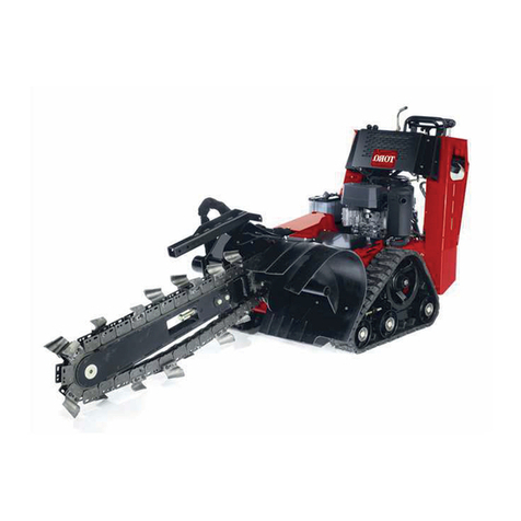
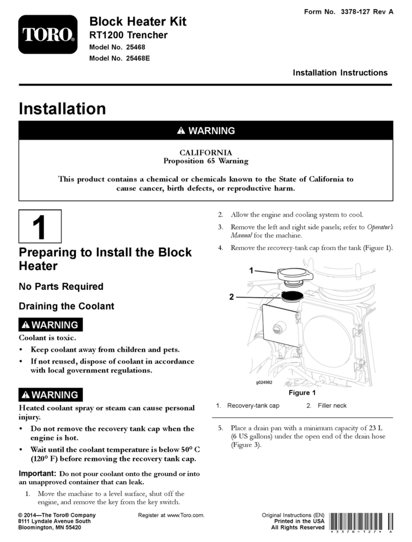
  9. Toro 25445 User manual

Toro 25445 User manual

Other Toro Lawn And Garden Equipment manuals
Toro Ultra Buggy 2500-T User manual

Toro

Toro Ultra Buggy 2500-T User manual

Toro 23210 User manual

Toro

Toro 23210 User manual

Toro 66205T User manual

Toro

Toro 66205T User manual
Toro 22368 User manual

Toro

Toro 22368 User manual

Toro 44911 User manual

Toro

Toro 44911 User manual

Toro TRX-16 User manual

Toro

Toro TRX-16 User manual

Toro 09501 User manual

Toro

Toro 09501 User manual

Toro 79090 User manual

Toro

Toro 79090 User manual

Toro 03662 User manual

Toro

Toro 03662 User manual
Toro 29516 User manual

Toro

Toro 29516 User manual

Toro Z-Stand 105-1621 User manual

Toro

Toro Z-Stand 105-1621 User manual

Toro 30701 User manual

Toro

Toro 30701 User manual

Toro 133-2861 User manual

Toro

Toro 133-2861 User manual

Toro 23702 User manual

Toro

Toro 23702 User manual

Toro 25497 User manual

Toro

Toro 25497 User manual

Toro Ultra Sonic Boom 41219 User manual

Toro

Toro Ultra Sonic Boom 41219 User manual

Toro Sand Pro 3040 User manual

Toro

Toro Sand Pro 3040 User manual

Toro 07263 User manual

Toro

Toro 07263 User manual

Toro Reelmaster 3555 User manual

Toro

Toro Reelmaster 3555 User manual

Toro 22615 User manual

Toro

Toro 22615 User manual

Toro Pro Control 138-7588 User manual

Toro

Toro Pro Control 138-7588 User manual

Toro Leaf Cart User manual

Toro

Toro Leaf Cart User manual

Toro Greensmaster 3000 Series User manual

Toro

Toro Greensmaster 3000 Series User manual

Toro 104-8950 User manual

Toro

Toro 104-8950 User manual

Popular Lawn And Garden Equipment manuals by other brands

Sunforce SOLAR user manual

Sunforce

Sunforce SOLAR user manual

GARDEN OF EDEN 55627 user manual

GARDEN OF EDEN

GARDEN OF EDEN 55627 user manual

Goizper Group MATABI POLMINOR instruction manual

Goizper Group

Goizper Group MATABI POLMINOR instruction manual

Rain Bird 11000 Series Operation & maintenance manual

Rain Bird

Rain Bird 11000 Series Operation & maintenance manual

Cub Cadet BB 230 brochure

Cub Cadet

Cub Cadet BB 230 brochure

EXTOL PREMIUM 8891590 Translation of the original user manual

EXTOL PREMIUM

EXTOL PREMIUM 8891590 Translation of the original user manual

Snapper 690179 installation instructions

Snapper

Snapper 690179 installation instructions

Exmark SAR481KA30 Operator's manual

Exmark

Exmark SAR481KA30 Operator's manual

Yazoo/Kees Z12 Operator's manual

Yazoo/Kees

Yazoo/Kees Z12 Operator's manual

Makita EM408MP Original instruction manual

Makita

Makita EM408MP Original instruction manual

Exmark Quest Bagger Setup instructions

Exmark

Exmark Quest Bagger Setup instructions

Manitou Systems AS960 Operator's manual

Manitou Systems

Manitou Systems AS960 Operator's manual

Vertex 1/3 HP Maintenance instructions

Vertex

Vertex 1/3 HP Maintenance instructions

GHE AeroFlo 80 manual

GHE

GHE AeroFlo 80 manual

Land Pride Post Hole Diggers HD25 Operator's manual

Land Pride

Land Pride Post Hole Diggers HD25 Operator's manual

Yazoo/Kees Z9 Commercial Collection System Z9A Operator's & parts manual

Yazoo/Kees

Yazoo/Kees Z9 Commercial Collection System Z9A Operator's & parts manual

Premier designs WindGarden 26829 Assembly instructions

Premier designs

Premier designs WindGarden 26829 Assembly instructions

Snapper 1691351 installation instructions

Snapper

Snapper 1691351 installation instructions

manuals.online logo
manuals.online logoBrands
  • About & Mission
  • Contact us
  • Privacy Policy
  • Terms and Conditions

Copyright 2025 Manuals.Online. All Rights Reserved.

FormNo.3388-147RevA
AuxiliaryValveKit
RT600TractionUnit
ModelNo.25445
InstallationInstructions
Safety
WARNING
CALIFORNIA
Proposition65Warning
Thisproductcontainsachemicalorchemicals
knowntotheStateofCaliforniatocausecancer,
birthdefects,orreproductiveharm.
SafetyandInstructional
Decals
Safetydecalsandinstructionsareeasily
visibletotheoperatorandarelocatednear
anyareaofpotentialdanger.Replaceany
decalthatisdamagedorlost.
125-6696
1.Rotatecounterclockwise4.Moveright
2.Rotateclockwise5.Lowertheguard
3.Moveleft6.Raisetheguard
©2014—TheToro®Company
8111LyndaleAvenueSouth
Bloomington,MN55420
Registeratwww.T oro.com.OriginalInstructions(EN)
PrintedintheUSA
AllRightsReserved*3388-147*A
Installation
LooseParts
Usethechartbelowtoverifythatallpartshavebeenshipped.
DescriptionQty.Use
Nopartsrequired–Preparethemachine.
Auxiliaryvalve1
Bracket1
Bolts(M8)3
90-degreetting(1/2-inchmale,5/8-inch
male)2
Installtheauxiliaryvalve.
Cover1
Clipnut3
Bolts(M6)3
90-degreetting(5/8-inchmale,male)2
90-degreetting(5/8-inchmale,5/8-inch
female)1
Teetting1
Hydraulichose(30inches)1
Directionalvalveassembly1
Bolts(5/16inch)2
Washer2
Installthedirectionalvalvecoverandassembly.
ShortHydraulictube1
Longhydraulictube1
Hydraulichose(24inches)1
90-degreetting(5/8-inchmale,3/4-inch
female)2
Decal1
Cableties2
Installthehydraulichosesandthedecal.
PreparingtheMachine
1.Movethemachinetoalevelsurface.
2.Settheparkingbrakeandlowertheattachmentsto
theground.
3.Shutoffthemachineandremovethekey.
4.Removetheboltsandcoverfromtheexistingbulkhead
mountasshowninFigure1.
g027024
2
1
Figure1
1.Bolts2.Cover
2
InstallingtheAuxiliaryValve
1.Applythread-lockingadhesivetothe3bolts(M8)and
securetheauxiliaryvalvetothebracketasshownin
Figure2.
Figure2
1.90-degreettings3.Bolts(M8)
2.Bracket
2.Installthe2ttings(90degree,1/2-inchmale,5/8-inch
male)ontothevalveasshowninFigure2.
Note:Ensurethatthettingontherightsideis
turned25degrees.
3.Removethebolts,washers,andnutssecuringthelower
rightsidepaneltotheROPS(Figure3).
Figure3
4.SecuretheauxiliaryvalveassemblytotheROPSusing
thebolts,washers,andnutsremovedintheprevious
stepasshowninFigure3.
InstallingtheDirectionalValve
CoverandAssembly
1.Installthe3clipnutsontothenewcoverassemblyas
showninFigure4.
Figure4
1.Bolts(M6)3.Cover
2.Clipnuts
2.Applythread-lockingadhesivetothe3bolts(M6)and
securethecovertothebulkheadmountasshownin
Figure4.
3.Installbothofthe90-degreettings(5/8-inchmale,
male),theTeetting,andthe90-degreetting
(5/8-inchmale,5/8-inchfemale)ontothedirectional
valveasshowninFigure5.
Figure5
1.90-degreetting(5/8-inch
male,5/8-inchmale)
4.Valvenut
2.90-degreetting(5/8-inch
male,5/8-inchfemale)
5.Coil
3.Teetting6.90-degreetting(5/8-inch
male,male)
4.Torquethettingsto142to162N-m(105to120ft-lb).
5.Installthe30-inchhoseontothelower90-degree
tting(5/8-inchmale,male)(Figure5).
6.Loosenthevalvenutandrotatethecoilonthe
directionalvalve180degrees(Figure5).
3
7.Torquethevalvenutto142to162N-m(105to120
ft-lb).
8.Applythread-lockingadhesivetothe2bolts(5/16
inch)andlooselysecurethedirectionalvalveassembly
tothecoverusingthe2bolts,and2washersasshown
inFigure6.
Note:Makesurethatport2isshowingontopofthe
valve.
Figure6
1.Bolts(5/16inch)3.Valvettingcover
2.Washers
9.Removethevalvettingcovercurrentlyinstalledon
thebulkheadasshowninFigure6.
InstallingtheHydraulicHoses
andtheDecal
1.Installthelonghydraulictubefromtheteettingto
thefurthest90degreettingonthebulkheadassembly
asshowninFigure7.
Figure7
1.Longhydraulictube3.Shorthydraulictube
2.90-degreetting(5/8inch
male,3/4inchfemale)
2.Installtheshorthydraulictubefromthe90-degree
ttingontopofthedirectionalvalveassemblytothe
closest90-degreettingonthebulkheadassemblyas
showninFigure7.
3.Connectthe30-inchhose,previouslyinstalledonthe
bottomofthedirectionalvalveassembly,totheoutside
90-degreettingontheauxiliaryvalveasshownin
Figure8.
Figure8
1.Hydraulichose(30inches)3.Hydraulichose(24inches)
2.90-degreetting(5/8male,
female)
4.Installthe24-inchhosefromtheinnermost90-degree
ttingtothe90-degreettingontheteevalve
connectedtothedirectionalvalveassemblyasshown
inFigure8.
5.Securethehosestogetherwiththe2cableties.
6.Tightentheboltssecuringthedirectionalvalve
assemblytothecover(Figure6).
7.InstallthedecalasshowninFigure9.
1
g027031
Figure9
1.Decal
4