manuals.online logo
Brands
  1. Home
  2. •
  3. Brands
  4. •
  5. Toro
  6. •
  7. Lawn And Garden Equipment
  8. •
  9. Toro 135-7423 User manual

Toro 135-7423 User manual

Other Toro Lawn And Garden Equipment manuals
Toro ProCore 864 User manual

Toro

Toro ProCore 864 User manual

Toro Groundsmaster 3280-D User manual

Toro

Toro Groundsmaster 3280-D User manual

Toro PROCORE 440 User manual

Toro

Toro PROCORE 440 User manual

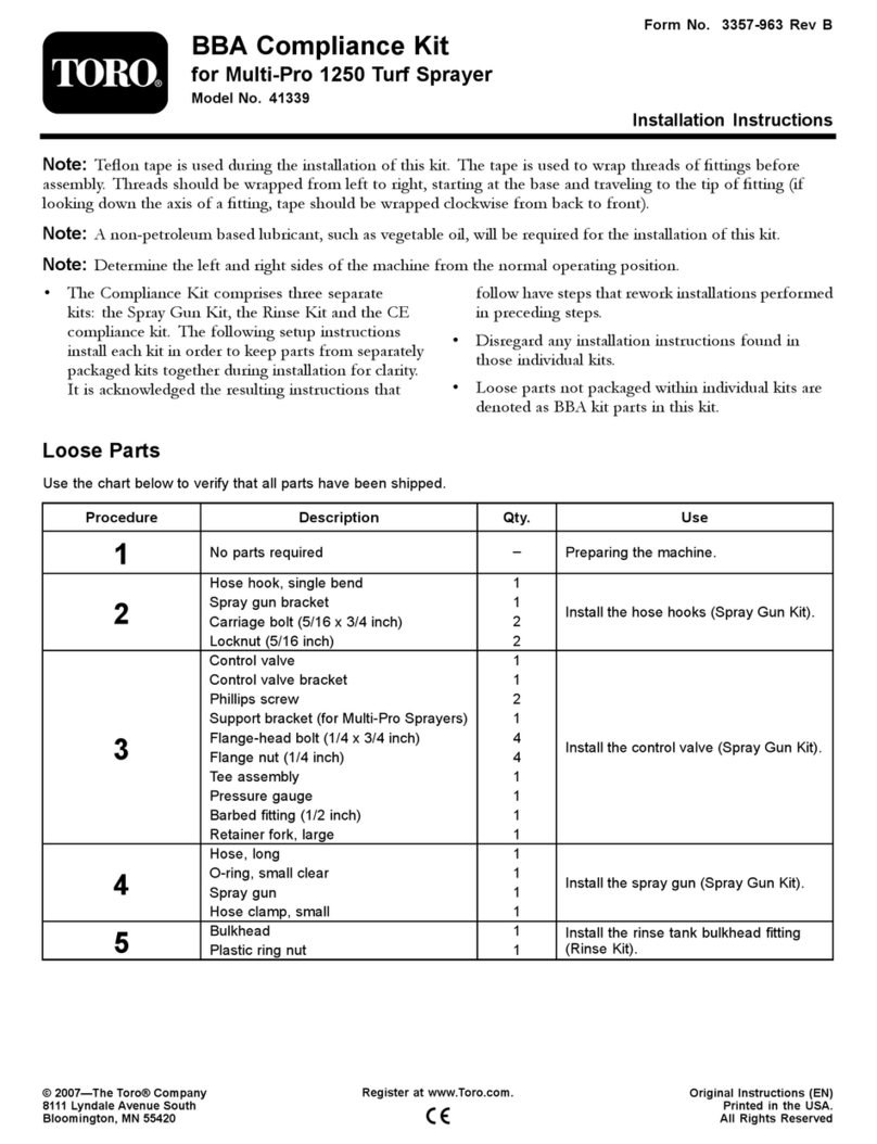
Toro 41339 User manual

Toro

Toro 41339 User manual
Toro Tree Forks 22438 User manual

Toro

Toro Tree Forks 22438 User manual

Toro 119-4121 User manual

Toro

Toro 119-4121 User manual

Toro 22305A User manual

Toro

Toro 22305A User manual

Toro 22980 User manual

Toro

Toro 22980 User manual

Toro Greensmaster 3150 User manual

Toro

Toro Greensmaster 3150 User manual

Toro 66000T User manual

Toro

Toro 66000T User manual

Toro 23515 User manual

Toro

Toro 23515 User manual

Toro MULTI PRO 5600 User manual

Toro

Toro MULTI PRO 5600 User manual

Toro Greensmaster TriFlex 3300 Series User manual

Toro

Toro Greensmaster TriFlex 3300 Series User manual

Toro 29521 User manual

Toro

Toro 29521 User manual

Toro Reelmaster 3555 User manual

Toro

Toro Reelmaster 3555 User manual
Toro 22602THD User manual

Toro

Toro 22602THD User manual

Toro 33518 User manual

Toro

Toro 33518 User manual

Toro 41602 User manual

Toro

Toro 41602 User manual

Toro AERATOR HC 4000 User manual

Toro

Toro AERATOR HC 4000 User manual

Toro Ultra Buggy 2500-T User manual

Toro

Toro Ultra Buggy 2500-T User manual

Toro Greensmaster TriFlex 3300 User manual

Toro

Toro Greensmaster TriFlex 3300 User manual

Toro Bullseye QuickGroom 700 User manual

Toro

Toro Bullseye QuickGroom 700 User manual

Toro 200 Z Master Series User manual

Toro

Toro 200 Z Master Series User manual

Toro 3200 User manual

Toro

Toro 3200 User manual

Popular Lawn And Garden Equipment manuals by other brands

Sunforce SOLAR user manual

Sunforce

Sunforce SOLAR user manual

GARDEN OF EDEN 55627 user manual

GARDEN OF EDEN

GARDEN OF EDEN 55627 user manual

Goizper Group MATABI POLMINOR instruction manual

Goizper Group

Goizper Group MATABI POLMINOR instruction manual

Rain Bird 11000 Series Operation & maintenance manual

Rain Bird

Rain Bird 11000 Series Operation & maintenance manual

Cub Cadet BB 230 brochure

Cub Cadet

Cub Cadet BB 230 brochure

EXTOL PREMIUM 8891590 Translation of the original user manual

EXTOL PREMIUM

EXTOL PREMIUM 8891590 Translation of the original user manual

Snapper 690179 installation instructions

Snapper

Snapper 690179 installation instructions

Exmark SAR481KA30 Operator's manual

Exmark

Exmark SAR481KA30 Operator's manual

Yazoo/Kees Z12 Operator's manual

Yazoo/Kees

Yazoo/Kees Z12 Operator's manual

Makita EM408MP Original instruction manual

Makita

Makita EM408MP Original instruction manual

Exmark Quest Bagger Setup instructions

Exmark

Exmark Quest Bagger Setup instructions

Manitou Systems AS960 Operator's manual

Manitou Systems

Manitou Systems AS960 Operator's manual

Vertex 1/3 HP Maintenance instructions

Vertex

Vertex 1/3 HP Maintenance instructions

GHE AeroFlo 80 manual

GHE

GHE AeroFlo 80 manual

Land Pride Post Hole Diggers HD25 Operator's manual

Land Pride

Land Pride Post Hole Diggers HD25 Operator's manual

Yazoo/Kees Z9 Commercial Collection System Z9A Operator's & parts manual

Yazoo/Kees

Yazoo/Kees Z9 Commercial Collection System Z9A Operator's & parts manual

Premier designs WindGarden 26829 Assembly instructions

Premier designs

Premier designs WindGarden 26829 Assembly instructions

Snapper 1691351 installation instructions

Snapper

Snapper 1691351 installation instructions

manuals.online logo
manuals.online logoBrands
  • About & Mission
  • Contact us
  • Privacy Policy
  • Terms and Conditions

Copyright 2025 Manuals.Online. All Rights Reserved.

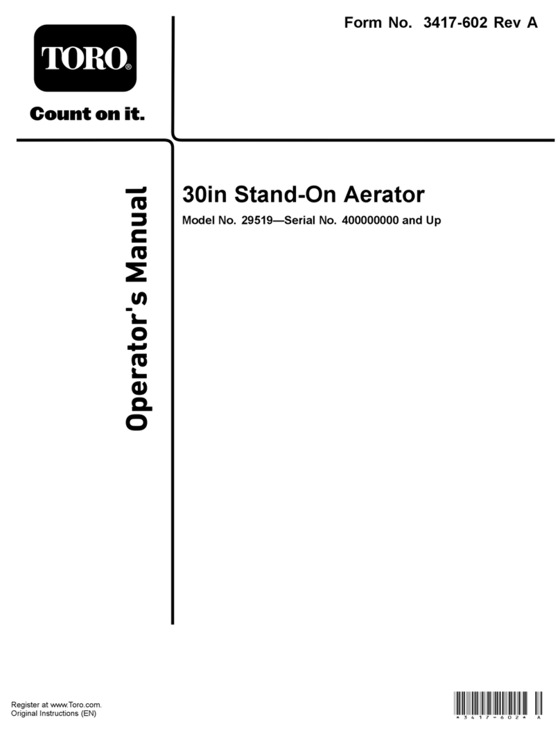
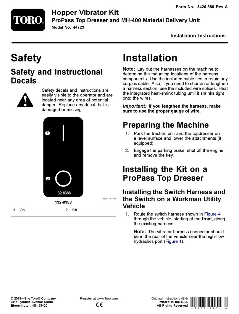
FormNo.3433-517RevF
CEConversionKit
24inStand-OnAerator
ModelNo.135-7423
InstallationInstructions
Safety
SafetyandInstructional
Decals
Safetydecalsandinstructionsare
easilyvisibletotheoperatorandare
locatednearanyareaofpotential
danger.Replaceanydecalthatis
damagedormissing.
decal135-3183
135-3183
1.Bypassleverpositionfor
pushingthemachine.
3.Bypassleverpositionfor
operatingthemachine.
2.Readtheinstructions
beforeservicingor
performingmaintenance.
Installation
1
PreparingtheMachine
NoPartsRequired
Procedure
1.Parkthemachineonalevelsurfaceandengage
theparkingbrake.
2.Shutofftheengineandremovethekey.
3.Waitforallmovingpartstostop.
4.Allowthemachinetocool.
5.Disconnectthesparkplug;refertothe
Operator’sManualforyourmachine.
2
RemovingtheCoversand
Guards
NoPartsRequired
Removingthe
Hydraulic-ComponentCovers
1.Remove2thumbscrewsthatsecurethe
hydraulic-componentcovertothemachine,and
removethecover(Figure1).
Note:Discardthecoversandthumbscrews.
©2021—TheToro®Company
8111LyndaleAvenueSouth
Bloomington,MN55420Registeratwww.Toro.com.
OriginalInstructions(EN)
PrintedintheUSA
AllRightsReserved*3433-517*
g349556
Figure1
Leftsideshown
1.Right
hydraulic-component
cover
3.Lefthydraulic-component
cover
2.Thumbscrews4.Covermountbrackets
2.Repeatstep1fortheotherhydraulic-component
cover.
RemovingtheChainGuards
1.Removethe2angelocknuts,2washers,2
carriagebolts,andange-headscrew(1/4x1/2
inch)securingeachchainguardtothemachine,
andremovetheguard(Figure2).
Note:Retainthewashers.Discardthechain
guard,carriagebolts,angelocknuts,and
ange-headscrew.
g293458
Figure2
Leftsideshown
1.Carriagebolt4.Chainguard
2.Washer5.Flange-headscrew(1/4x
1/2inch)
3.Flangelocknut
2.Repeatstep1attheothersideofthemachine.
RemovingtheRearPlatformCover
Removethe2thumbscrewsthatsecuretherear
platformguardtotheframeofthemachine,and
removetheguard(Figure3).
Note:Retaintheguard.Discardthethumbscrews.
g349527
Figure3
1.Mountingange(frame)3.Rearplatformguard
2.Thumbscrew
2
3
PreparingtheCoversand
Guards
Partsneededforthisprocedure:
1LeftCEhydraulic-componentcover
1RightCEhydraulic-componentcover
4Flange-headcapscrew(3/8x1inch)
4Retainingring(3/8inch)
1LeftCEchainguard
1RightCEchainguard
4Flange-headcapscrew(10x35mm)
4Retainingring(10mm)
2Clipnut(5/16inch)
2Flange-headcapscrew(1/4x5/8inch)
2Retainingring(1/4inch)
Assemblingthe
Hydraulic-ComponentCover
1.Assembleaange-headcapscrew(3/8x1inch)
throughtheholeintothehydraulic-component
cover(Figure4).
g349593
Figure4
1.Right
hydraulic-component
cover
3.Lefthydraulic-component
cover
2.Flange-headcapscrew
(3/8x1inch)
4.Retainingring(3/8inch)
2.Securethecapscrewtothecover(Figure4)with
aretainingring(3/8inch).
3.Repeatsteps1and2fortheother
hydraulic-componentcover.
AssemblingtheChainGuards
1.Assemble2ange-headcapscrew(10x35mm)
throughtheholeintothehydraulic-component
cover(Figure5).
g349594
Figure5
1.Flange-headcapscrew(10
x35mm)
5.Retainingring(10mm)
2.Clipnut(5/16inch)6.LeftCEchainguard
3.Flange-headcapscrew
(1/4x5/8inch)
7.Retainingring(1/4inch)
4.RightCEchainguard
2.Securethecapscrewstothecover(Figure5)
witharetainingring(10mm).
3.Assembleange-headcapscrew(1/4x5/8inch)
throughtheholeintothehydraulic-component
cover(Figure5).
4.Securethecapscrewstothecover(Figure5)
witharetainingring(1/4inch).
5.Repeatsteps1through4fortheotherCEchain
guard.
3
AssemblingtheRearPlatform
Cover
1.Assemble2ange-headcapscrews(3/8x1
inch)throughtheholesintotherearplatform
cover(Figure6)thatyouremovedinRemoving
theRearPlatformCover(page2).
g349595
Figure6
1.Retainingring(3/8inch)3.Flange-headcapscrew
(3/8x1inch)
2.Rearplatformcover
2.Securethecapscrewstothecover(Figure6)
with2retainingring(3/8inch).
4
InstallingtheCEGuards
Partsneededforthisprocedure:
2Full-threadedbolt(3/8x2inches)
2Flangelocknut(3/8inch)
4Clipnut(10mm)
2Flange-headcapscrew(5/16x1inch)
2Retainingring(5/16inch)
InstallingtheCE
Hydraulic-ComponentCovers
1.Partiallythreadthefull-threadedbolt(3/8x2
inches)throughthethreadedinsertintheguard
mountatthesideoftheframe(Figure7).
g349606
Figure7
1.Flangelocknut(3/8inch)3.Full-threadedbolt(3/8x2
inches)
2.Guardmount(sidesofthe
frame)
2.Assembleaangelocknut(3/8inch)ontothe
full-threadedbolt(Figure7).
Note:Ensurethatthe2or3threadsofthebolt
protrudebeyondtheendofthenut.
3.Repeatsteps1and2attheothersideofthe
machine.
4.Aligntheangelocknut(3/8inch)inthe
hydraulic-componentcovertothethreaded
insertinthetopguardmount(Figure8).
4
g349610
Figure8
1.Right
hydraulic-component
cover
3.Lefthydraulic-component
cover
2.Flange-headcapscrew
(3/8x1inch)
4.Full-threadedbolt(3/8x2
inches)
5.Aligntheslotinthehydraulic-componentcover
withthefull-threadedbolt(3/8x2inches).
6.Assemblethehydraulic-componentcovertothe
machine,andthreadtheange-headcapscrew
andfull-threadedboltintothethreadedinserts.
7.Torquetheange-headcapscrewand
full-threadedboltto37to45N∙m(27to33ft-lb).
8.Repeatsteps4through7fortheother
hydraulic-componentcoverattheothersideof
themachine.
PreparingtoInstalltheChain
Guards
1.Assemble2clipnut(10mm)ontotheguard
mount(Figure9).
g349720
Figure9
1.Clipnuts(10mm)2.Guardmount
2.Repeatstep1attheothersideofthemachine.
3.Atthebottomofthemachine,assemblea
ange-headcapscrew(5/16x1inch)through
holeinthehydromountbracket(Figure10).
5
g349723
g349722
Figure10
1.Frontofthemachine3.Hydromountbracket
2.Retainingring(5/16inch)4.Flange-headcapscrew
(5/16x1inch)
4.Securethecapscrewtothebracket(Figure10)
witharetainingring(5/16inch).
g349721
Figure11
1.FrontoftheMachine3.Rightsideofthemachine
2.Leftsideofthemachine
InstallingtheChainGuards
1.Aligntheange-headboltsoftheCEchain
guardwiththeclipnutsandthreadedspaceron
themachine(Figure12).
g349735
Figure12
LeftCEChainGuardShown
1.Guardmount2.CEchainguard
2.LooselyassembletheCEchainguardtothe
machinewiththeange-headbolts.
3.Torquetheange-headcapscrewsasshownin
Figure13.
6
g349736
Figure13
1.Frontofthemachine
4.Repeatsteps1through3fortheCEchainguard
attheothersideofthemachine.
InstallingtheRearPlatformCover
1.Alignthe2ange-headcapscrewsintherear
platformcoverwiththethreadedinsertsofthe
framemountinganges(Figure14).
g349739
Figure14
1.Mountingange(frame)3.Rearplatformcover
2.Flange-headcapscrew
(3/8x1inch)
2.Looselyassemblethecovertotheangeswith
thecapscrews.
3.Torquetheange-headcapscrewsto37to45
N∙m(27to33ft-lb).
7
5
InstallingtheDecals
Partsneededforthisprocedure:
1Decal133-5623(machinemanufacturerdate)
1Decal142-2156(CEsound)
Procedure
1.Installdecals133-5623(machinemanufacturer
date)and142-2156(CEsound)totheleftframe
plateasshowninFigure15.
g293414
Figure15
1.Decal142-2156(CE
sound)
2.Decal133-5623(machine
manufacturerdate)
2.Permanentlymarkthemonthandyearon
decal133-5623fortheinstallationofthiskit
installation.
6
FinishingInstallingtheKit
NoPartsRequired
Procedure
Connectthesparkplug;refertotheOperator’s
Manualforyourmachine.
8