Toro 04475 User manual
Other Toro Lawn And Garden Equipment manuals

Toro
Toro Bullseye QuickGroom 550 User manual

Toro
Toro Shovel 31803T User manual
Toro
Toro 23515 User manual

Toro
Toro Greensmaster TriFlex 3300 User manual
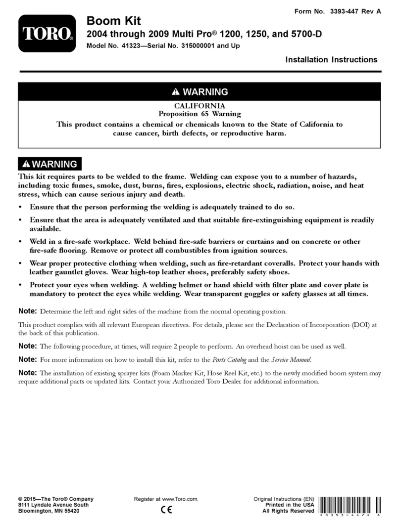
Toro
Toro 41323 User manual

Toro
Toro Green Keeper 212 User manual
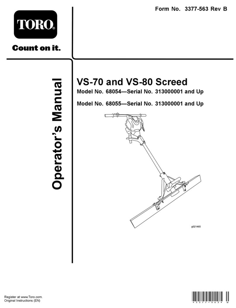
Toro
Toro VS-70 User manual
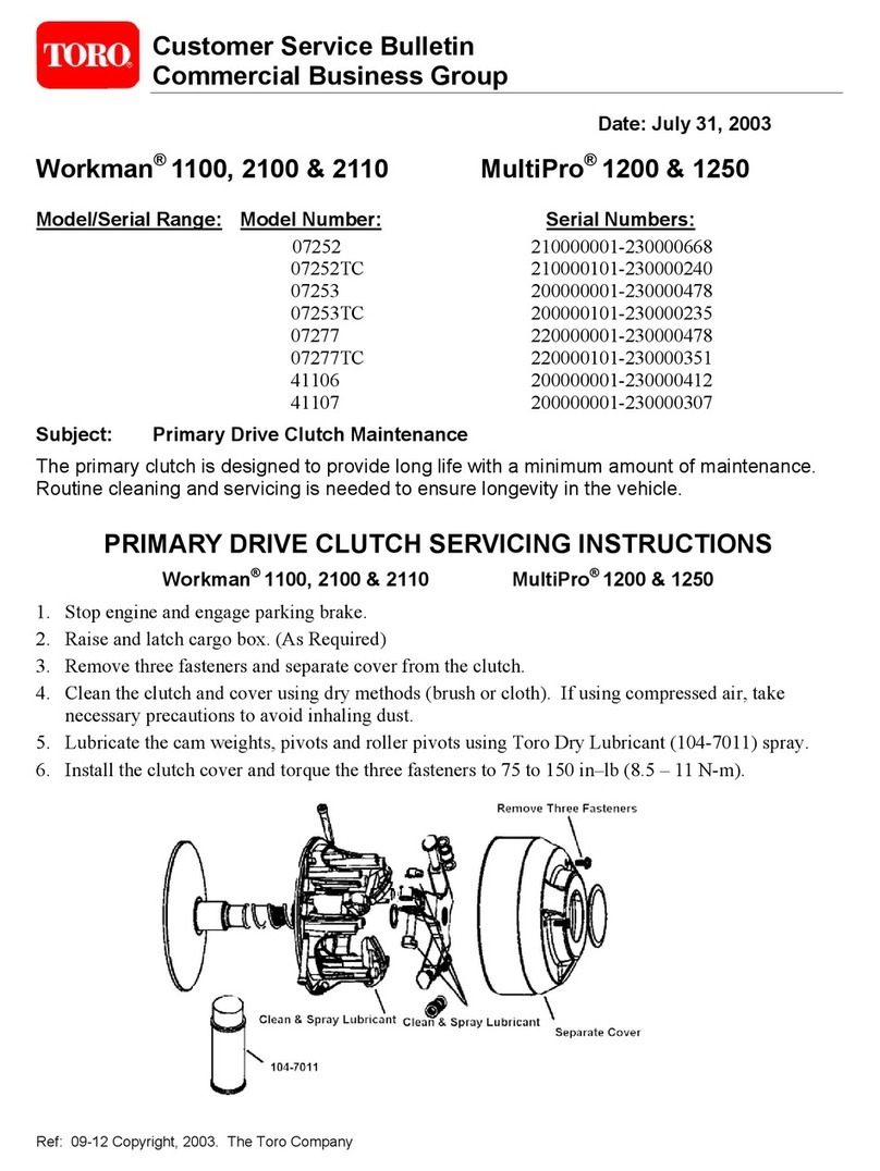
Toro
Toro Workman 1100 Reference manual
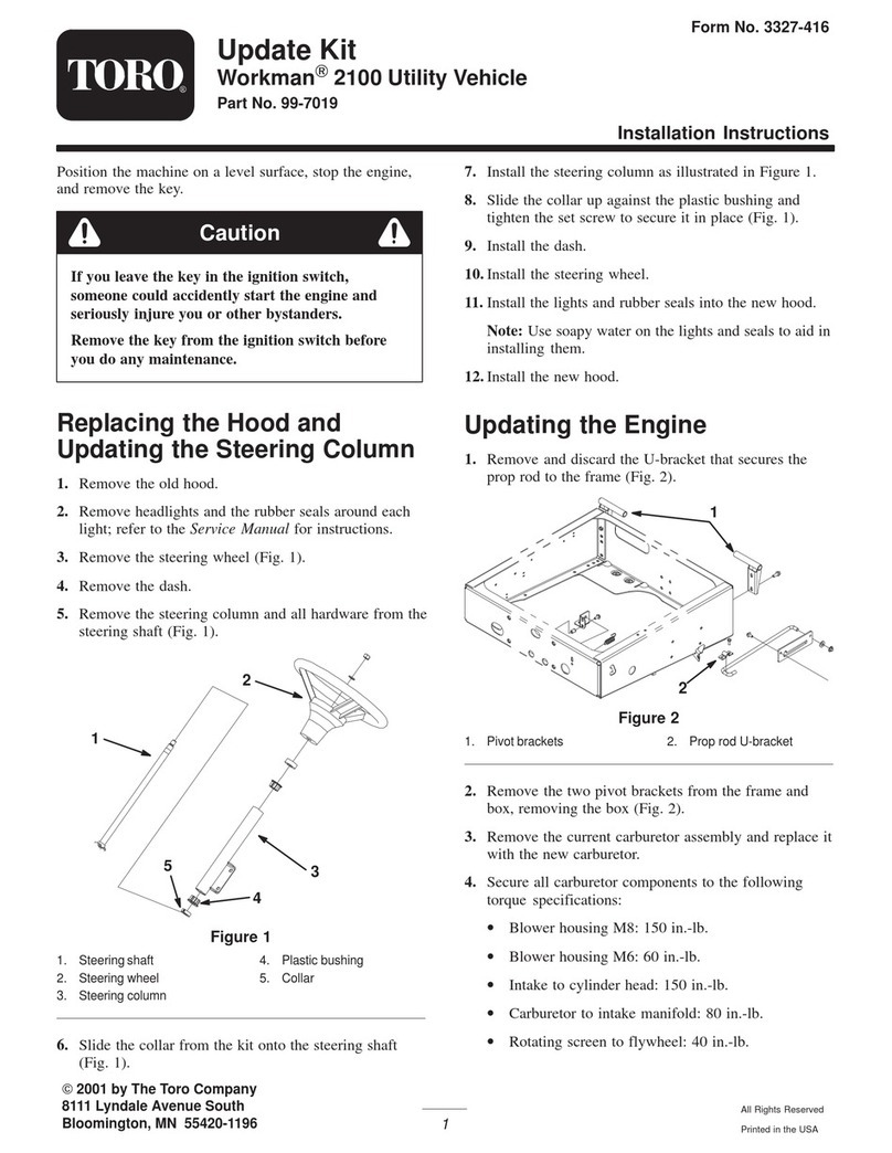
Toro
Toro 99-7019 User manual

Toro
Toro 22368 User manual
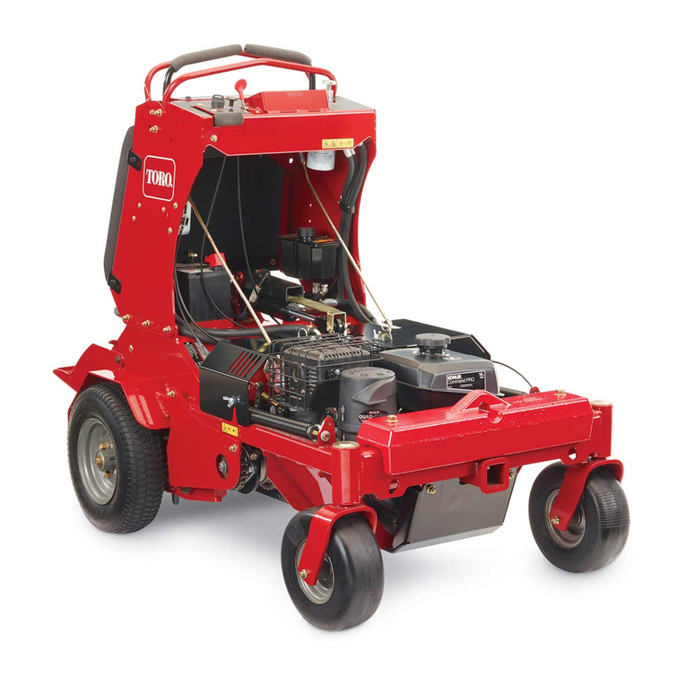
Toro
Toro 29517 User manual

Toro
Toro Greensmaster 3250-D User manual
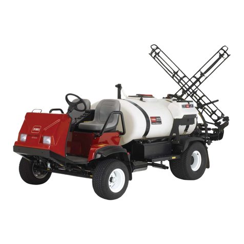
Toro
Toro Multi Pro 5700-D User manual

Toro
Toro Sand Pro 3040 User manual

Toro
Toro 22805 User manual

Toro
Toro HoverPro 450 User manual

Toro
Toro Power Shovel 39909 User manual
Toro
Toro TRX-20 User manual
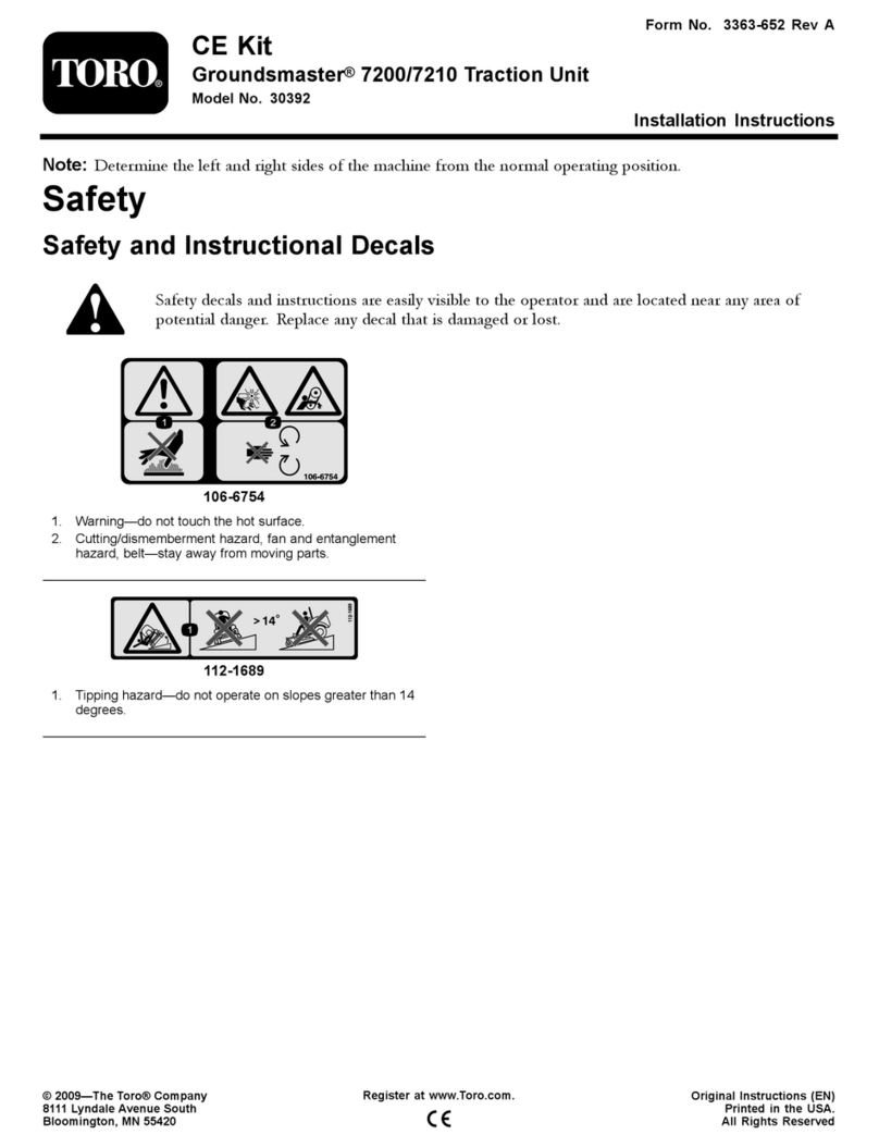
Toro
Toro 30392 User manual
Toro
Toro procore sr54 User manual
Popular Lawn And Garden Equipment manuals by other brands

Vertex
Vertex 1/3 HP Maintenance instructions

GHE
GHE AeroFlo 80 manual

Millcreek
Millcreek 406 Operator's manual

Land Pride
Land Pride Post Hole Diggers HD25 Operator's manual

Yazoo/Kees
Yazoo/Kees Z9 Commercial Collection System Z9A Operator's & parts manual

Premier designs
Premier designs WindGarden 26829 Assembly instructions

AQUA FLOW
AQUA FLOW PNRAD instructions

Tru-Turf
Tru-Turf RB48-11A Golf Green Roller Original instruction manual

BIOGROD
BIOGROD 730710 user manual

Land Pride
Land Pride RCF2784 Operator's manual

Makita
Makita UM110D instruction manual

BOERBOEL
BOERBOEL Standard Floating Bar Gravity Latch installation instructions
