Toro groundsmaster 455-D User manual

OPERATOR S
MANUAL
FORM NO. 3325-366
MODEL NO. 30450 2100
00001
& UP
MODEL NO. 30455TC 2100
00001
& UP
GROUNDSMASTER
¤
455-D
¤
©The Toro Company—2000
3325-366 Rev A

Table of Contents 1
Safety 2
Sound & Vibration Levels 4
Symbol Glossary 5
Specifications 8
Before Operating 10
Check The Engine Oil 10
Check The Cooling System 10
Fill The Fuel Tank 10
Check The Hydraulic Circuit Oil 11
Check The Front Axle Oil Level 12
Check The Rear Axle Lubricant
(Model 30455 Only) 13
Check Bi-Directional Clutch Lubricant 13
Check Tire Pressure 14
Check The Torque Of Wheel Nuts Or Bolts 14
Check The Lubricant In The Gear Box 14
Adjusting The Height Of Cut 14
Safety Doors 16
Controls 17
Operating 19
Starting and Stopping 19
Priming the Fuel System 19
Checking the Interlock System 19
Operating Characteristics 20
Operating Tips 21
Maintenance 22
Minimum Recommended Maintenance
Intervals 22
Greasing 24
General Air Cleaner Maintenance 27
Servicing the Air Cleaner 27
Engine Oil and Filter 28
Fuel System 28
Engine Cooling System 29
Engine Timing Belt 30
Changing Hydraulic Oil 30
Replacing The Hydraulic Filter 31
Checking Hydraulic Lines and Hoses 32
Hydraulic System Test Ports 32
Adjusting The Traction Drive For Neutral 33
Changing Front Axle Lubricant 33
Changing Rear Axle Lubricant
(Model 30455 only) 34
Changing Bi-Directional Clutch
Lubricant (Model 30455 Only) 34
Rear Wheel Toe In 34
Adjusting Service Brakes 35
Adjusting Pro Belt 35
Adjusting The Clutch 36
Battery Care 36
Fuses 36
Cutting Unit Maintenance 38
General Maintenance 38
Separating The Cutting Unit From
The Traction Unit 39
Mounting the Cutting Unit to
The Traction Unit 39
Safety Door Adjustment 40
Blade Adjustment 40
Adjusting Belt Tension 41
Replacing Drive Belts 41
Servicing Front Bushings In Castor Arms 43
Servicing Castor Wheels And Bearings 43
Preparation for Seasonal Storage 46
Blade Removal And Installation 44
Inspecting And Sharpening The Blade 45
1
Table of Contents

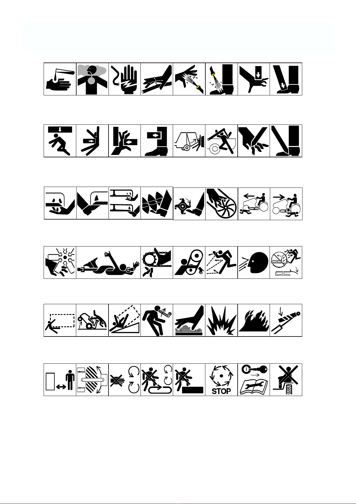
Improper use or maintenance by the operator or owner
can result in injury. To reduce the potential for injury,
comply with these safety instructions and always pay
attention to the safety alert symbol, which means
CAUTION, WARNING, or DANGER—“personal
safety instruction.” Failure to comply with the
instruction may result in personal injury or death.
Before Operating
1. Read and understand the contents of this manual
before starting and operating the machine. Become
familiar with the controls and know how to stop the
machine and engine quickly.
A free replacement manual is available by sending
the complete model and serial number to:
The Toro Company
8111 Lyndale Avenue South
Minneapolis, Minnesota 55420.
2. Never allow children to operate the machine. Do
not allow adults to operate machine without proper
instruction. Only trained operators who have read
this manual should operate this machine.
3. Never operate the machine when under the
influence of drugs or alcohol.
4. Keep all shields, safety devices and decals in place.
If a shield, safety device or decal is defective,
illegible or damaged, repair or replace it before
operating the machine. Also tighten any loose nuts,
bolts or screws to ensure machine is in safe
operating condition.
5. Always wear substantial shoes. Do not operate
machine while wearing sandals, tennis shoes,
sneakers or when barefoot. Do not wear loose
fitting clothing that could get caught in moving
parts and possibly cause personal injury. Wearing
safety glasses, safety shoes, long pants and a
helmet is advisable and required by some local
ordinances and insurance regulations.
6. Assure interlock switches are adjusted correctly so
engine cannot be started unless traction pedal is in
NEUTRAL and cutting unit is DISENGAGED.
7. Remove all debris or other objects that might be
picked up and thrown by the blades or fast moving
2
components from other attached implements. Keep
all bystanders away from operating area.
8. Since diesel fuel is highly flammable, handle it
carefully:
A. Use an approved fuel container.
B. Do not remove fuel tank cap while engine is
hot or running.
C. Do not smoke while handling fuel.
D. Fill fuel tank outdoors and only to within an
inch from the top of the tank, not the filler
neck. Do not overfill.
E. Wipe up any spilled fuel.
While Operaing
9. Sit on the seat when starting and operating the
machine.
10. Before starting the engine:
A. Engage the parking brake.
B. Make sure traction pedal is in NEUTRAL and
cutting decks are DISENGAGED. Move axle
shift to HI or LO position.
C. After engine is started, release parking brake
and keep foot off traction pedal. Machine must
not move. If movement is evident, the neutral
return mechanism is adjusted incorrectly;
therefore, shut engine off and adjust until
machine does not move when traction pedal is
released. Refer to Adjusting Traction Drive for
Neutral, page ???.
11. Seating capacity is one person. Therefore, never
carry passengers.
12. Do not run engine in a confined area without
adequate ventilation. Exhaust fumes are hazardous
and could possibly be deadly.
13. Check interlock switches daily for proper operation.
Do not rely entirely on safety switches—use
common sense. If a switch fails, replace it before
operating the machine. The interlock system is for
your protection, so do not bypass it. Replace all
interlock switches every two years.
14. Using the machine demands attention and to
Safety

prevent loss of control:
A. Operate only in daylight or when there is good
artificial light.
B. Drive slowly. Avoid sudden stops and starts.
C. Watch for holes or other hidden hazards.
D. Look behind machine before backing up.
E. Do not drive close to a sand trap, ditch, creek
or other hazard.
F. Reduce speed when making sharp turns and
turning on a hillside.
15. Traverse slopes carefully. Do not start or stop
suddenly when traveling uphill or downhill. Never
shift axle when moving. Machine must be on a flat
surface and/or brakes must be engaged to prevent
freewheeling.
16. Operator must be skilled and trained in how to
drive on hillsides. Failure to use caution on slopes
or hills may cause loss of control and vehicle to tip
or roll possibly resulting in personal injury or
death.
17. This product may exceed noise levels of 85 dB(A)
at the operator position. Ear protectors are
recommended, for prolonged exposure, to reduce
the potential of permanent hearing damage.
18. When operating 4-wheel drive machine, always use
the seat belt and roll-over protection system
together and have seat pivot retaining pin installed.
19. If engine stalls or loses headway and cannot make
it to the top of a slope, do not turn machine around.
Always back slowly straight down the slope.
20. Raise cutting decks and latch securely in transport
position before driving from one work area to
another.
21. DON' T TAKE AN INJURY RISK! When a
person or pet appears unexpectedly in or near the
mowing area, STOP MOWING. Careless
operation, combined with terrain angles, ricochets,
or improperly positioned guards can lead to thrown
object injuries. Do not resume mowing until area is
cleared.
22. Do not touch engine, muffler or exhaust pipe while
3
engine is running or soon after it is stopped. These
areas could be hot enough to cause burns.
23. If cutting deck strikes a solid object or vibrates
abnormally, stop immediately, turn engine off, set
parking brake and wait for all motion to stop.
Inspect for damage. If damaged, repair or replace
any components before operating.
24. Before getting off the seat:
A. Set parking brake.
B. Move traction pedal to neutral and axle shift to
HI or LO position.
C. Disengage cutting decks and wait for blades to
stop.
D. Stop engine and remove key from switch.
E. Do not park on slopes unless wheels are
chocked or blocked.
25. Use only a rigid tow bar if it becomes necessary to
tow machine. Use trailer for normal transport.
Maintenance
26. Before servicing or making adjustments, stop
engine and remove key from the switch.
27. Make sure machine is in safe operating condition
by keeping all nuts, bolts and screws tight.
28. Make sure all hydraulic line connectors are tight,
and all hydraulic hoses and lines are in good
condition before applying pressure to the system.
29. Keep body and hands away from pin hole leaks or
nozzles that eject high pressure hydraulic fluid. Use
cardboard or paper to find hydraulic leaks.
Hydraulic fluid escaping under pressure can
penetrate skin and cause injury. Fluid accidentally
injected into the skin must be surgically removed
within a few hours by a doctor familiar with this
form of injury or gangrene may result.
30. Before disconnecting or performing any work on
the hydraulic system, all pressure in system must be
relieved by lowering cutting units to the ground and
stopping engine.
31. If major repairs are ever needed or assistance is

desired, contact an authorized Toro distributor.
32. To reduce potential fire hazard, keep engine area
free of excessive grease, grass, leaves and dirt.
Clean protective screen on back of machine
frequently. Never wash a warm engine or electrical
connections with water.
33. If engine must be running to perform maintenance
or an adjustment, keep hands, feet, clothing and
other parts of the body away from cutting units and
other moving parts. Keep all bystanders away.
34. Do not overspeed the engine by changing governor
setting. To assure safety and accuracy, have an
Authorized Toro Distributor check maximum
engine speed.
35. Shut engine off before checking or adding oil to the
crankcase.
36. Disconnect battery before servicing the machine. If
battery voltage is required for troubleshooting or
test procedures, temporarily connect the battery.
37. At the time of manufacture, the machine
conformed to the safety standards for riding
mower. Ballast weight, mounted to rear of traction
unit, is required for machine to conform to safety
standard. DO NOT remove ballast weight at any
time. To assure optimum performance and
continued safety certification of the machine, use
genuine Toro replacement parts and accessories.
Replacement parts and accessories made by other
manufacturers may result in non-conformance with
the safety standards, and the warranty may be
voided.
Sound Pressure Level
This unit has an equivalent continuous A-weighted
sound pressure at the operator ear of: 89 dB(A), based
on measurements of identical machines per Directive
98/37/EC and amendments.
Sound Power Level
This unit has a guaranteed sound power level of: 105
dB(A)/1pW, based on measurements of identical
machines per Directive 2000/14/EC and amendments.
Vibration level
Hand-Arm
This unit does not exceed a vibration level of 2.5 m/s2at
the hands based on measurements of identical machines
per ISO 5349 procedures.
4

5
Symbol Glossary
Caustic liquids,
chemical burns to
fingers or hand
Poisonous
fumes or toxic
gases, asphyxiation
Electrical shock,
electrocution High pressure
fluid, injection
into body
High pressure
spray, erosion of
flesh
High pressure
spray, erosion of
flesh
Crushing of
fingers
or hand,
force
applied from
above
Crushing of
toes or foot, force
applied from above
Crushing of
whole body,
applied from
above
Crushing of
torso, force
applied from side
Crushing of fingers
or hand/, force
applied from side
Crushing of
whole body Crushing of
head, torso and
arms
Cutting of
fingers or hand Cutting of footCrushing of leg,
force applied
from side
Severing of
fingers or hand,
mower blade
Severing of
toes or foot,
mower blade
Severing of
toes or fingers,
rotary mower
blade
Cutting or
entanglement of
foot, rotating auger
Severing of
foot, rotating
knives
Severing of
fingers or hand,
impeller blade
Dismember-
ment, front engine
mower in forward
motion
Dismember-
ment, front engine
mower in rearward
motion
Severing of
fingers or hand,
engine fan
Whole body entanglement,
implement input drive line Fingers or
hand entangle-
ment, chain
drive
Hand & arm
entanglement,
belt drive
Thrown or flying
objects, whole
body exposure
Thrown or
flying objects,
face exposure
Thrown or flying
objects, rotary
mover
Runover/back-
over, vehicle Machine
tipping, riding
mower
Machine rollover,
ROPS (rear
engine mower)
Stored energy
hazard, kickback
or upward motion
Hot surfaces,
burns to fingers
or hands
Explosion Fire or open
flame
Secure lifting
cylinder with locking
device before getting
in hazardous area
Do not step on
loading platform
if PTO is connect-
ed to tractor &
engine is running
Do not step Wait until all
machine comp-
onents have
completely
stopped before
touching them
Shut off engine
& remove key
before perform-
ing maintenance
or repair work
Stay a safe
distance from
the machine
Stay clear of
articulation area
while engine is
running
Do not open
or remove safety
shields while
engine is
running
Riding on this
machine is allowed
only on a passen-
ger seat & only if the
driver’s view is not
hindered

6
Fasten seat
belts Safety alert
triangle Outline safety
alert symbol Read operator’s
manual Fire, open light
and smoking
prohibited
Eye protection
must be worn
Consult technical
manual for proper
service
procedures
Hearing
protection must
be worn
Caution, toxic
risk
Head protection
must be worn Flush with water Engine Transmission Hydraulic systemFirst aid
Oil Coolant (water) Intake air Exhaust gas Pressure Level indicator Liquid level
Brake system
Disengage
Filter Temperature Failure/
Malfunction Start switch/
mechanism On/start Off/stop Engage
Plus/increase/
positive polarity Minus/decrease/
negative polarity Horn Battery charging
condition Hourmeter/
elapsed operating
hours
Fast Slow Continuous
variable, linear
Volume empty Volume full Machine travel
direction,
forward/
rearward
Control lever
operating
direction, dual
direction
Control lever
operating
direction, multiple
direction
Clockwise
rotation Counter-clock-
wise rotation Grease
lubrication
point
Oil lubrication
point Lift point Jack or
support point Draining/
emptying Engine lubricat-
ing oil Engine
lubricating
oil pressure
Engine lubricating
oil level Engine lubricating
oil filter
Engine lubricating
oil temperature Engine coolant Engine coolant
pressure Engine coolant
filter Engine coolant
temperature Engine intake/
combustion air
Engine intake/com-
bustion air pressure
Engine intake/air
filter

7
Engine start Engine stop Engine failure/
malfunction Engine rotational
speed/frequency Choke Primer (start aid) Electrical preheat
(low temperature
start aid)
n/min
Transmission
oil
Transmission
oil pressure Transmission
oil temperature Transmission
failure/malfunctionClutch Neutral High Low Forward
NHLF
Reverse Park First gear Second gear
Third gear (other #'s
may be used until the
maximum # of forward
gears is reached.)
Hydraulic oil Hydraulic oil
pressure
Hydraulic oil
level
RP 2 31
Hydraulic oil
filter Hydraulic oil
temperature Hydraulic oil
failure/malfunction Fuel level
Parking brake Fuel Fuel filter Fuel system
failure/malfunction
Lock Unlock Differential lock 4-Wheel drive Power Take-OffDiesel fuel Unleaded fuel Headlights
Cutting unit,
lower Cutting unit,
hold Cutting unit,
float
Cutting unit Cutting unit,
raise
Power Take-Off,
rotational speed Blade cutting
element Blade cutting
element, height
adjustment
Cutting unit,
transport
position
Cutting unit,
raise to transport
position
Cutting unit,
lower to transport
position
Attachment
lower Attachment
raise Spacing distance Snow thrower,
collector auger Traction
Above working
temperature
range
Drilling Manual metal
arc welding Manual Water pump Keep dry Weight Do not dispose
in the garbage CE logo

Traction Unit
Engine: Peugeot, four-cycle, four-cylinder, 1.9 liter
(1,900 cc) displacement, liquid-cooled diesel engine.
23.5:1 compression ratio. Low idle—1,500 rpm, high
idle—3,000 rpm. Oil capacity is 5.3 qts. with filter.
Cooling System: Capacity is 13.2 l (3.5 gal) of 50/50
mixture of Peugeot recommended anti-freeze.
Fuel System: Capacity is 53 liter (14 gallon) of #1 or
#2 diesel fuel.
Hydraulic System: Reservoir capacity is 24.6 liters
(6.5 gallon). Replaceable spin-on filter element.
Traction System: Ground speed: Low Range; 0–10.5
kmh, 0–6.5 mph (0–5.5 mph. with mechanical speed
limiter interlock) forward and 0–4.8 kmh, 0–3 mph
reverse. High Range): 0–24.1 kmh, 0–15 mph (0–20
kmh, 0–12.4 m.p.h. with mechanical speed limiter
interlock) forward and 0–8 kmh, 0–5 mph reverse.
Front Axle: Two-speed axle is designed to withstand
heavy-duty slope operation and side loading. Separate
mowing and transport selections for faster and more
efficient machine operation. Neutral position allows
easy towing.
Rear Axles: Two-Wheel Drive—The large diameter
wheel spindles are designed for durability and long
wear, yet provide superior stability and maneuverability.
Four-Wheel Drive—Heavy-duty, agricultural type.
Hydraulic drive with “on demand” bi-directional clutch
and balanced weight distribution provides superior
traction on hillsides.
Tires/Wheels: High flotation turf tread tires on de-
mountable rims. Front tires: (2) 26 x 12.0-12, 8 ply.
Rear tires: (2) 20 x 10.0-10, 6 ply. Tire pressure 138 kPa
(20 psi).
Seat: Adjustable fore and aft travel and weight.
Diagnostic System: Test ports for: forward and
reverse traction (2-wheel drive), front and rear axle
motors (4 wheel drive), lift and counterbalance circuit,
steering circuit and charge circuit.
8
Steering System: Automotive type, full power.
Brakes: Totally enclosed, non asbestos, dry multi-disc
individual wheel and parking brakes on front traction
wheels. Brakes controlled by individual pedals operated
by the left foot. Dynamic braking through closed-loop
hydrostatic drive.
Electrical System: 12-volt battery with 530 cold
cranking Amps @ –18°C (0° F). 55-amp alternator,
ammeter, starter, key switch and automatic temperature
controlled glow plug controller. Separately-fused run,
deck and instrument/accessory circuits.
Interlock System: Stops the engine if operator gets off
the seat while the cutting deck drive switch is engaged
or the traction pedal is forward or reverse. Prevents the
engine from starting unless the traction pedal is in
neutral and the cutting deck is disengaged. Prevents the
cutting deck from operating unless the axle shift is in LO
range.
Warning Lights:
Glow plug indicator
Engine oil pressure warning
Engine coolant temperature warning
Charge indicator
Water in Fuel
Low-Water indicator
Indicators:
Engine coolant temperature gauge
Fuel gauge
Hour meter
The Cutting Unit
Type: 320 cm (126 inch) width of cut, seven-blade,
front-mounted rotary. 137 cm (54 inch) width of cut,
three-blade center section. Two 94 cm (36 inch) width of
cut wings; 229 cm (90 in.) width of cut with one wing
up. Rear discharge with even dispersion over the entire
width of cut.
Mowing Rate: Mows up to 19 hectars/hour. at 10.5 kmh
(6.5 mph).
Trimability: Trims on both sides.
Height-of-Cut: Adjustable from 2.5–12.7 cm (1–5
Specifications

inches) in 1.2 cm (0.5 inch) increments. Seven 48 cm
(19 inches) long, 6 mm (1/4”) thick, and 64 mm (2-1/2
in.) wide, heat treated steel blades.
Belt Idlers: Self-tensioning permanently lubricated
idlers.
Wing Decks: Wings can be hydraulically raised from
the operator’s seat for transport or cutting with either
wing and center deck or center deck only. Wings cut
from level to 15° up and down. Further lift disengages
the blade and applies a blade brake.
Suspension/Caster Wheels: Four front and two rear
pneumatic castor tires with ball bearings. Center deck
tires: 26–8.3 cm (10.25 in. x 3.25 in.). Wing deck tires:
20 x 8.3 cm (8 in. x 3.25 in. An anti-scalp cup is located
on each blade. Three anti-scalp rollers on the center
deck. Deck is hydraulically counterbalanced.
General Specifications (approx.):
Overall Length:
With the deck installed 340 cm (134 in.)
Overall Width:
Transport 190.5 cm (75 in.)
Mowing 323 cm (127 in.)
Height: 147 cm (58 in.)
With rollover protection
system installed 208 cm (82 in.)
Wheel Tread:
(Front) 129.5 cm (51 in.)
(Rear) 104 cm (41 in.)
Wheel Base: 142 cm (56 in.)
Wheel Tread: 132 cm (52 in.)
Dry Weight:
2-Wheel Drive 1,418 kg (3,800 lb)
4-Wheel Drive 1,455 kg (3,900 lb)
Optional Equipment
Broom Kit, Contact Your Local Toro Distributor
Snowthrower, Contact Your Local Toro Distributor
Roll-Over Protection Kit, Contact Your Local Toro
Distributor (Standard on Model 30455)
4-Post Canopy Kit, Contact Your Local Toro Distributor
Spark Arrestor Muffler, Part No. 94-5637
Segmented Wheel Kit, Part No. 76-1880
Brake Light Kit, Part No. 92-7763
Gear Box Pulley (Tip Speed 14,500), Part No. 86-3100
Windshield Kit, Contact Your Local Toro Distributor
Cruise Control Kit, Model No. 30485
Road Light Kit, Model No. 30471
Mulcher Kit, Model No. 30475 Cab, Contact Your
Local Toro Distributor
Additional Weights, Contact Your Local Toro
Distributor
Low Seat Option, Contact Your Local Toro Distributor
Specifications and design subject to change without
notice.
9

10
Check the Engine Oil
Crankcase capacity is 5 liters (5.3 qt) with filter.
1. Park the machine on a level surface. Release the
hood latch and open the hood.
Figure 1
1. Hood latch
2. Remove the dipstick from the tube cap, wipe it
clean and reinstall the dipstick into the tube cap.
Pull it out again and check the oil level on the
dipstick: The oil level must always be in the notch
area on the dipstick.
Figure 2
1. Dipstick/tube cap
3. If the oil level is low, remove the tube cap and add
SAE 10W–30 CD oil until the level reaches the top
of notch on the dipstick. DO NOT OVERFILL.
4. Install the oil tube cap.
5. Close the hood and secure the latch.
Check the Cooling System
Capacity of the system is 13.2 liters (3.5 gal).
1. Park the machine on a level surface. Release the
hood latch and open the hood.
2. Check the coolant level. The coolant level should
be up to or above the mounting tabs on the
degasser tank, when the engine is cold.
Figure 3
1. Degasser tank
3. If the coolant is low, remove the degasser tank cap
and add a 50/50 mixture of water and Peugeot
recommended anti-freeze (Toro Part No. 93-7213).
Do not use water only or alcohol/ methanol-
based coolants.
IMPORTANT: Do not remove the black plastic
cap on the degasser tank.
4. Install the degasser tank cap.
5. Close the hood and secure the latch.
Fill the Fuel Tank
1. Park the machine on a level surface. Release the
hood latch and open the hood.
2. Remove the fuel tank cap.
Before Operating
1
1
1
Before servicing or making adjustments to the
machine, stop the engine and remove the key from the
switch
CAUTION

Figure 4
1. Fuel tank cap
3. Fill the tank to no more than one inch below the
bottom of the filler neck with No. 2 diesel fuel. DO
NOT OVER FILL. Then install the cap.
Note: For temperatures below 0° C (32° F), No. 1
diesel fuel or a blend should be used.
4. Close the hood and secure the latch.
Check the Hydraulic Circuit Oil
The hydraulic system is designed to operate on Mobil
DTE 15M or equivalent anti-wear hydraulic fluid. The
machine’s reservoir is filled at the factory with
approximately 24.6 L of Mobil DTE 15M hydraulic
fluid. However, check the level of hydraulic fluid
before the engine is first started and daily thereafter.
Appropriate hydraulic oils are listed below.
Group 1 Hydraulic Fluid (Moderate climate—
average duty)
Note: The fluids within this group are interchangeable.
ISO VG 46/68 multi-viscosity anti-wear hydraulic
fluid
Mobil DTE 15M
Amoco Rykon Premium ISO 46
Castrol AWH 46
Conoco Hydroclear AW MV46
Gulf Harmony HVI 46 AW
Kendall Hyken Golden MV SAE 5W-20
Pennzbell AWX MV46
Phillips Magnus A KV 5W-20
Shell Tellus T 46
Sunoco Sun Hyd. Oil 2105
Texaco Rando HDZ 46
Universal Tractor Hydraulic Fluid
Mobil Mobilfluid 424
Amoco 1000 Fluid
Chevron Tractor Hydraulic Fluid
Conoco Hydroclear Powertran
Esso Hydraul
Gulf Universal Tractor Fluid
Kendall Hyken 052
Marathon Marafluid Super HT
Pennzoil Hydra-trans
Phillips HG Fluid
Shell Donax TD
76 Lubricants Hydraulic/Tractor Fluid
Sunoco TH Fluid
Texaco TDH
Group 2 Hydraulic Fluid (Hot Climate- Heavy Duty)
Note: The fluids within this group are interchangeable.
ISO VG 68 anti-wear hydraulic fluid
Mobil DTE 26
Amoco Rykon AW No. 68
Castro[ AWS 68
Chevron Hydraulic Oil AW ISO 68
Conoco Hydroclear AW 68
Exxon Nuto H 68
Gulf Harmony 68AW
Kendall Four Seasons AW 68
Marathon IS068
Pennzbell AW Hydraulic Oil 68
Phillips Magnus A ISO 68
Shell Tellus 68
76 Lubricants AW 68
Sunoco SunVis 868
Texaco Rando HD 68
IMPORTANT- Group 1 fluids are recommended for
use at typical ambient temperatures 0°C to 41°C.
The ISO Type 46/48 fluid has been found to offer
11
1
Because diesel fuel is highly flammable, use
caution when storing or handling it. Do not
smoke while filling the fuel tank. Do not fill the
fuel tank while the engine is running, hot, or
when the machine is in an enclosed area. Always
fill the fuel tank outside and wipe up any spilled
diesel fuel before starting the engine. Store the
fuel in a clean, safety-approved container and
keep the cap in place. Use diesel fuel for the
engine only; not for any other purpose.
DANGER

optimal performance in a wide range of temperature
conditions for the average user. The Universal
Tractor Fluids offer similar performance for those
who prefer them, with perhaps some slight loss of
efficiency at high ambient temperatures compared to
the Type 46/48 fluids.
Group 2 fluids are recommended for heavy-duty use
in hot climates where ambient temperatures range
from about 20°C to 49°C. Use at lower ambient
temperatures may result in hard starting, increased
engine laboring while cold, sluggish or non-operating
valves while cold and high filter back pressure due to
the higher viscosity of these fluids.
Note: When changing from one type of hydraulic fluid
to another, be certain to remove all the old fluid from
the system, as some fluids are incompatible with others.
Important: Use only hydraulic oils specified. Other
fluids could cause system damage.
Note: A red dye additive for the hydraulic system fluid
is available in19.8 ml bottles. One bottle is sufficient
for 22 L of hydraulic fluid. Order Part No. 44-2500
from your Authorized Toro Distributor.
1. Park the machine on a level surface. Make sure the
machine has been operated so the oil is warm.
Release the hood latch and open the hood. Check
the oil level by viewing the sight gauge. If oil is
visible in the gauge, the oil level is sufficient.
2. If the oil level is not visible in the gauge, remove
the cap from the hydraulic oil reservoir and slowly
add Mobil DTE 15 or equivalent hydraulic oil until
the level reaches the middle (maximum) of the
sight gauge. DO NOT OVER FILL.
IMPORTANT: To prevent system
contamination, clean the tops of hydraulic oil
containers before puncturing. Make sure the
pour spout and funnel are clean.
3. Install the reservoir cap, close the hood and secure
the latch.
Figure 5
1. Sight gauge
2. Hydraulic reservoir cap
Check the Front Axle Oil Level
The front axle is shipped from the factory filled with
SAE 80–90 weight gear lubrication. However, check the
level before the engine is first started and every 50 hours
thereafter. Capacity is 378cl (128 oz.). Check daily for
signs of oil loss.
1. Park the machine on a level surface.
2. Remove the access panel (Fig. 6), in the front of the
seat, to expose the front axle/dipstick.
Figure 6
1. Access panel
3. Unscrew the dipstick cap (Fig. 7) from the filler
neck and wipe it with a clean cloth. Screw the
dipstick cap finger tight onto the filler neck.
Unscrew the dipstick and check the level of
lubricant. If the level is not within 12mm (1⁄2 in.)
from the groove in the dipstick, add enough to raise
the level to the groove mark. DO NOT OVERFILL
by more than 12mm (1/2 inch) above the groove.
12
1
2
1

4. Screw the dipstick filler cap finger-tight onto the
filler neck. It is not necessary to tighten the cap
with a wrench.
Figure 7
1. Dipstick cap
Check the Rear Axle Lubricant
(Model 30455 Only)
The rear axle is shipped from the factory filled with
SAE 80–90 weight gear lubrication. However, check the
level before the engine is first started and every 50 hours
thereafter. Capacity is 237cl (80 oz).
1. Position the machine on a level surface.
2. Clean area around the (3) check plugs, (1) on each
end and (1) in the center (Fig. 8).
3. Remove the check plugs and make sure lubricant is
up to bottom of hole. If level is low, add enough
lubricant to bring the level up to the bottom of the
check plug holes.
Figure 8
1. Vent/fill plug
2. Check plug (3)
Figure 9
1. Check/fill plug
Check Bi-Directional Clutch
Lubricant
(Model 30455 Only) (Fig. 10)
The Bi-directional Clutch is shipped from the factory
filled with Mobil DTE 15 M anti-wear hydraulic fluid.
However, check the level before the engine is first
started and every 50 hours thereafter. Capacity is 8 oz.
Check daily for signs of oil loss.
1. Position the machine on a level surface.
2. Remove the check/fill plug from the clutch housing
and make sure lubricant is up to bottom of the hole.
If the level is low, add enough lubricant to bring the
level up to the bottom of the check/fill plug hole.
Note: Do not use gear lube in the clutch housing.
Figure 10
1. Clutch housing
2. Check/fill plug
3. Drain plug
13
1
1
3
2
1
2
1

Check Tire Pressure
The tires are over-inflated for shipping. Therefore,
release some of the air to reduce the pressure. Correct
air pressure in the front and rear tires is 138 kPa (20
psi).
IMPORTANT: Maintain even pressure in all tires to
assure a good quality-of-cut and proper machine
performance. DO NOT UNDER INFLATE.
Check the Torque of Wheel Nuts
Or Bolts
Check the Lubricant In the Gear
Box
The gear box in designed to operate on SAE 80–90
weight gear lubrication. Although the gear box is
shipped with lubricant from the factory, check the
lubricant’s level before operating the cutting unit.
Check daily for signs of loss.
1. Position the machine and cutting unit on a level
surface.
2. Remove the check plug from the side of the gear
box and make sure lubricant is up to the bottom of
the hole. If the level of lubricant is low, remove the
fill plug on top of the gear case and add enough
lubricant to bring it up to the bottom of the hole
inside.
Figure 11
1. Filler plug/pressure relief valve
2. Check plug
Adjusting the Height Of Cut
The height-of-cut is adjustable from 2.5–12.7 cm (1 to 5
inches) in 12.7 mm (0.5 inch) increments. Positioning
the castor wheel axles in the top holes of the castor forks
or pivots (see chart below) allows low-range height-of-
cut settings from 2.5–8.3 cm (1 to 3-1/2 in); positioning
the castor wheel axles in the lower holes of the front
castor forks or rear castor pivots (see chart below)
allows a high-range height-of-cut settings from 6–12 cm
(2-1/2 to 5 in.)
14
0
54
1
2
3
2
4
1
3
0
5
123
3.52.5
1.5
2.5 3.5 4.5 543
SPACERS
LOW
HIGH
HEIGHT OF CUT—FRONT CASTOR WHEELS
1
2
4
32.5
1.5
3.5
4.5
5
HEIGHT OF CUT
—REAR CASTOR WHEELS
Torque the front wheel nuts to 45–55 ft-lb and the rear
wheel nuts or bolts to 85–100 ft lb after 1–4 hours of
operation and again after 10 hours of operation and
every 250 hours thereafter. Failure to maintain correct
torque could result in failure or loss of the wheel and
may result in personal injury.
WARNING

1. Start the engine and raise the cutting unit so the
height-of-cut can be changed. Stop the engine after
the cutting unit is raised.
2. Position all castor wheel axles in the same holes in
the castor forks or pivots.
Front Castor Wheels
1. Remove the height-of-cut cap from the spindle
shaft and slide the spindle out of the front castor
arm. Slide spacers onto the spindle shaft to get
desired height of cut.
2. Push the castor spindle through the front castor
arm. Install remaining spacers onto spindle and
install height-of-cut cap to secure the assembly.
Note: On the center deck only, make sure the
washer remains on the bottom of the spindle shaft.
Figure 12
1. Front castor wheel
2. Height-of-cut cap
3. Spacers
4. Washer (center deck only)
Rear Castor Wheels
1. Remove the hairpin cotter and height-of-cut pin
securing the rear castor pivot arm to the deck
bracket.
Figure 13
1. Rear castor pivot
2. Align the pivot arm holes with selected height-of-
cut bracket holes in the deck frame, install the
height-of-cut pin and secure with the hairpin cotter.
Rear Deck Straps
1. Lower the center and wing cutting units to the
ground: then raise the center cutting unit slightly,
until the rear deck straps hang freely on the lift arm
brackets. Stop the engine after the cutting unit is
raised.
Figure 14
1. Rear deck straps
2. Lift arm Brackets
2. Remove the hairpin cotter and height-of-cut pin
securing the rear deck strap to the height-of-cut
bracket on the deck.
3. Slide the deck strap forward or backward until the
holes in strap are aligned with selected height-of-cut
bracket holes in the deck frame, install the height-
of-cut pin and secure it with the hairpin cotter.
15
1
2.0
3.5
1.0
2.5
2.5
4.0
1.5
3.0
3.5
5.0
3.0
4.5
HEIGHT OF CUT
—REAR DECK STRAPS

Safety Doors
On each side of the center deck is a safety door that
opens and closes as the wing decks are lowered and
raised (Fig. 13). The doors open to provide overlap of
the cutting blades when the wing units are down. The
doors close to provide safety and protection when the
wing units are raised. Check to make sure the forward,
lower edge of door is even or 6 mm (1/4 in.) higher then
lower edge of door guide when wing decks are in the
fully raised, transport position. If an adjustment to the
door is required, refer to Adjusting The Safety Door.
Figure 15
1. Safety door
2. Door guide
3. Ball joint
4. Threaded rod
16
Check for correct operation of the safety doors each
time the deck is cleaned and repair when needed.
CAUTION

Cutting Unit Engagement Switch (Fig. 16)—Used to
start and stop cutting unit operation. Lift switch and move
forward to actuate the cutting unit. Center deck will engage
first followed by wing decks engaging approximately one
second later.
Figure 16
1. Cutting unit engagement switch
2. Glow plug indicator
3. Charge indicator
4. Key switch
5. Throttle control
6. Cutting unit lift controls
7. Coolant temperature gauge
8. Fuel gauge
9. Low-water indicator
10. Engine oil pressure warning light
11. Engine coolant temperature warning light
12. Water-in-fuel warning light
Glow Plug Indicator (Fig. 16)—Automatically actuates
proper glow period when the ignition key is turned to
ON. Illuminates when the glow plugs are actuated.
When the glow plugs are heated sufficiently, light goes
off indicating the engine is ready to start.
Charge Indicator (Fig. 16)—Illuminates when the
system charging circuit malfunctions.
Key Switch (Fig. 16)—Three positions: OFF, ON and
START. Turn the key to START and release it when the
engine begins running. To stop the engine, turn the key
to OFF.
Throttle Control (Fig. 16)—Move control forward to
increase the engine speed, backward to decrease speed.
Cutting Unit Lift Controls (Fig. 16)—The two outside
levers raise and lower the wing cutting units. The center
lever raises and lowers the whole cutting unit. The
engine must be running to lower the cutting unit. When
wing cutting units are raised higher than 15°, their
blades automatically disengage. To lower the cutting
unit just touch the levers momentarily.
Coolant Temperature Gauge (Fig. 16)—Shows the
temperature of engine coolant.
Fuel Gauge (Fig. 16)—Shows the amount of fuel in the
tank.
Low-Water Indicator (Fig. 16)—Indicates low water
level in the cooling system.
Engine Oil Pressure Warning Light (Fig. 16)—
Indicates dangerously low engine oil pressure.
Engine Coolant Temperature Warning Light (Fig.
16)—The red light illuminates and the engine stops
when temperature of the coolant exceeds 110° C
(230° F)
Water-In-Fuel Indicator (Fig. 16)—Indicates when
there is water in the fuel..
Seat (Fig. 17)—Seat adjusting lever on the left side of
the seat allows 4 inch fore and aft adjustment. The seat
adjusting knob on the front of the seat, adjusts the seat
for operator’s weight.
Figure 17
1. Seat adjusting lever
2. Seat adjusting knob
Traction Pedal (Fig. 18)—Controls forward and reverse
operation. Depress the top of the pedal to move forward
and the bottom to move backward. Ground speed
depends on how far the pedal is depressed. For no load,
maximum ground speed, fully depress the pedal while
the throttle is in FAST. For maximum power under load
17
2
1
Controls
6
4
13
2
10
5
11 7
8
12
9

or when going uphill, keep the engine rpm high by
having the throttle in FAST and the traction pedal
partially engaged. If engine rpm begins to decrease due
to load, gradually reduce the traction pedal pressure
until engine speed is increased.
To stop, reduce foot pressure on the traction pedal and
allow it to return to the center position. On extreme
downhill slopes, apply pressure to REVERSE side of
the pedal, or operate with heel on REVERSE and toe on
FORWARD portion of the pedal.
Figure 18
1. Traction pedal
2. Axle shift lever
3. Lockout knob
Speed Selector (Fig. 18)—The cam lever at the side of
the traction pedal can be rotated to maintain the desired
speed. Rotating the lever forward decreases speed and
backward increases speed.
Axle Shift Lever (Fig. 18)—Located on the right side of
console, the lever selects the front drive mode. Pull out
the lock-out knob, move the lever rearward for mowing
operation and forward for transport operation, then
release the knob to lock the selection. The lever must be
in LO position to mow. Middle position (N) is for
towing.
IMPORTANT: On model 30455, the lever must be in
LO to operate in 4-wheel drive.
CAUTION: The machine must be on a flat surface
and the brakes engaged when shifting the axle from
HI to LO
Brake Pedals (Fig. 19)—Two foot pedals at the lower
left operate individual wheel brakes for turning
assistance, parking and for better side hill traction. The
locking pin is for parking.
Figure 19
1. Brake pedals
2. Parking brake latch
3. Steering wheel tilt lever
Parking Brake Latch (Fig. 19)—A knob on the left side
of console actuates the parking brake lock. To engage
the parking brake, connect the pedals with the locking
pin, push down on both pedals and pull the parking
brake latch out. To release the parking brake, depress
both pedals until the parking brake latch retracts.
Steering Wheel Tilt Lever (Fig. 19)—The lever on the
left side of console lets the steering wheel to be adjusted
for operator comfort.
Transport Latches (Fig. 20)—Four latches secure the
cutting unit and wings in upright position for transport.
Figure 20
1. Transport latch (4)
Horn—In the center of steering wheel. Operates only
when the key switch is in ON.
Hour Meter (Under Hood)—Shows total hours that the
machine has been operated.
18
1
1
3
2
1
3
2

Starting and Stopping
1. Sit on the seat and keep your foot off the traction
pedal. Assure the parking brake is engaged, the
traction pedal is in NEUTRAL and the cutting unit
engagement switch is in the DISENGAGED
position.
2. Turn the ignition switch to ON. When the glow
plug indicator light goes off, the engine is ready to
START.
3. Turn the ignition key to START. Release the key
when the engine starts.
4. To stop, disengage and move all controls to
NEUTRAL and set the parking brake. Turn the key
to OFF and remove it from switch. Raise and latch
all the cutting units in transport position.
Priming the Fuel System
IMPORTANT: The fuel system may need to be
primed when a new engine is started for the first
time, if it runs out of fuel or if maintenance is
performed on the fuel system.
1. Unlatch and raise the hood.
2. Insert a 48 mm (3/16) hose over bleed screw and
run other end into a container to catch fuel.
3. Loosen the fuel filter/water separator bleed screw
(Fig. 21) a few turns. Pump the priming plunger
until a steady stream of fuel comes out of the hole
in the bleed screw. When fuel stops foaming,
tighten the bleed screw during the down stroke of
the priming plunger. Wipe up any spilled fuel.
Note: Priming the fuel filter without opening the
bleed screw may damage the priming plunger.
4. Pump the priming plunger until resistance is felt.
Try to start the engine. If the engine does not start
repeat step 3.
Figure 21
1. Hood plunger
2. Bleed screw
Note: It may be necessary to bleed the air out of the
fuel line between the fuel filter/water separator and
the injection pump. To do this, loosen the fitting on
the injection pump (Fig. 22) and repeat bleeding
procedure.
Figure 22
1. Injection pump fitting
Checking the Interlock System
The purpose of the interlock system is to prevent the
engine from cranking or starting unless the traction
pedal is in NEUTRAL and the cutting unit engagement
switch is DISENGAGED. Also, the engine will stop
when the cutting unit engagement switch is engaged or
the traction pedal is depressed with the operator off the
seat.
19
1
2
1
Operating
Other manuals for groundsmaster 455-D
3
Table of contents
Other Toro Lawn And Garden Equipment manuals

Toro
Toro 44723 User manual

Toro
Toro Bullseye QuickGroom 710 User manual

Toro
Toro GreensPro 1240 User manual

Toro
Toro Sand Pro 2040Z User manual

Toro
Toro GreensPro 1240 User manual

Toro
Toro Sitework Systems 22420 User manual

Toro
Toro Greensmaster 3150 User manual

Toro
Toro 39519 User manual

Toro
Toro Tree Forks 22438 User manual

Toro
Toro 135-7423 User manual