Toro 03676 User manual

FormNo.3451-136RevB
Reelmaster®5510TractionUnit
ModelNo.03676—SerialNo.410080000andUp
Registeratwww.Toro.com.
OriginalInstructions(EN)*3451-136*

ThisproductcomplieswithallrelevantEuropean
directives;fordetails,pleaseseetheseparateproduct
specicDeclarationofConformity(DOC)sheet.
ItisaviolationofCaliforniaPublicResourceCode
Section4442or4443touseoroperatetheengineon
anyforest-covered,brush-covered,orgrass-covered
landunlesstheengineisequippedwithaspark
arrester,asdenedinSection4442,maintainedin
effectiveworkingorderortheengineisconstructed,
equipped,andmaintainedforthepreventionofre.
Theenclosedengineowner'smanualissupplied
forinformationregardingtheUSEnvironmental
ProtectionAgency(EPA)andtheCaliforniaEmission
ControlRegulationofemissionsystems,maintenance,
andwarranty.Replacementsmaybeorderedthrough
theenginemanufacturer.
WARNING
CALIFORNIA
Proposition65Warning
Dieselengineexhaustandsomeofits
constituentsareknowntotheStateof
Californiatocausecancer,birthdefects,
andotherreproductiveharm.
Batteryposts,terminals,andrelated
accessoriescontainleadandlead
compounds,chemicalsknownto
theStateofCaliforniatocause
cancerandreproductiveharm.Wash
handsafterhandling.
Useofthisproductmaycauseexposure
tochemicalsknowntotheStateof
Californiatocausecancer,birthdefects,
orotherreproductiveharm.
Introduction
Thismachineisaride-on,reel-bladelawnmower
intendedtobeusedbyprofessional,hiredoperators
incommercialapplications.Itisprimarilydesigned
forcuttinggrassonwell-maintainedturf.Usingthis
productforpurposesotherthanitsintendedusecould
provedangeroustoyouandbystanders.
Readthisinformationcarefullytolearnhowtooperate
andmaintainyourproductproperlyandtoavoid
injuryandproductdamage.Youareresponsiblefor
operatingtheproductproperlyandsafely.
Visitwww.T oro.comformoreinformation,including
safetytips,trainingmaterials,accessoryinformation,
helpndingadealer,ortoregisteryourproduct.
Wheneveryouneedservice,genuineToroparts,or
additionalinformation,contactanAuthorizedService
DealerorToroCustomerServiceandhavethemodel
andserialnumbersofyourproductready.Figure1
identiesthelocationofthemodelandserialnumbers
ontheproduct.Writethenumbersinthespace
provided.
Important:Withyourmobiledevice,youcan
scantheQRcodeontheserialnumberplate(if
equipped)toaccesswarranty,parts,andother
productinformation.
g266613
Figure1
1.Modelandserialnumberlocation
ModelNo.
SerialNo.
Thismanualidentiespotentialhazardsandhas
safetymessagesidentiedbythesafety-alertsymbol
(Figure2),whichsignalsahazardthatmaycause
seriousinjuryordeathifyoudonotfollowthe
recommendedprecautions.
g000502
Figure2
Safety-alertsymbol
Thismanualuses2wordstohighlightinformation.
Importantcallsattentiontospecialmechanical
informationandNoteemphasizesgeneralinformation
worthyofspecialattention.
©2022—TheToro®Company
8111LyndaleAvenueSouth
Bloomington,MN554202
Contactusatwww.Toro.com.
PrintedintheUSA
AllRightsReserved

Contents
Safety.......................................................................4
GeneralSafety...................................................4
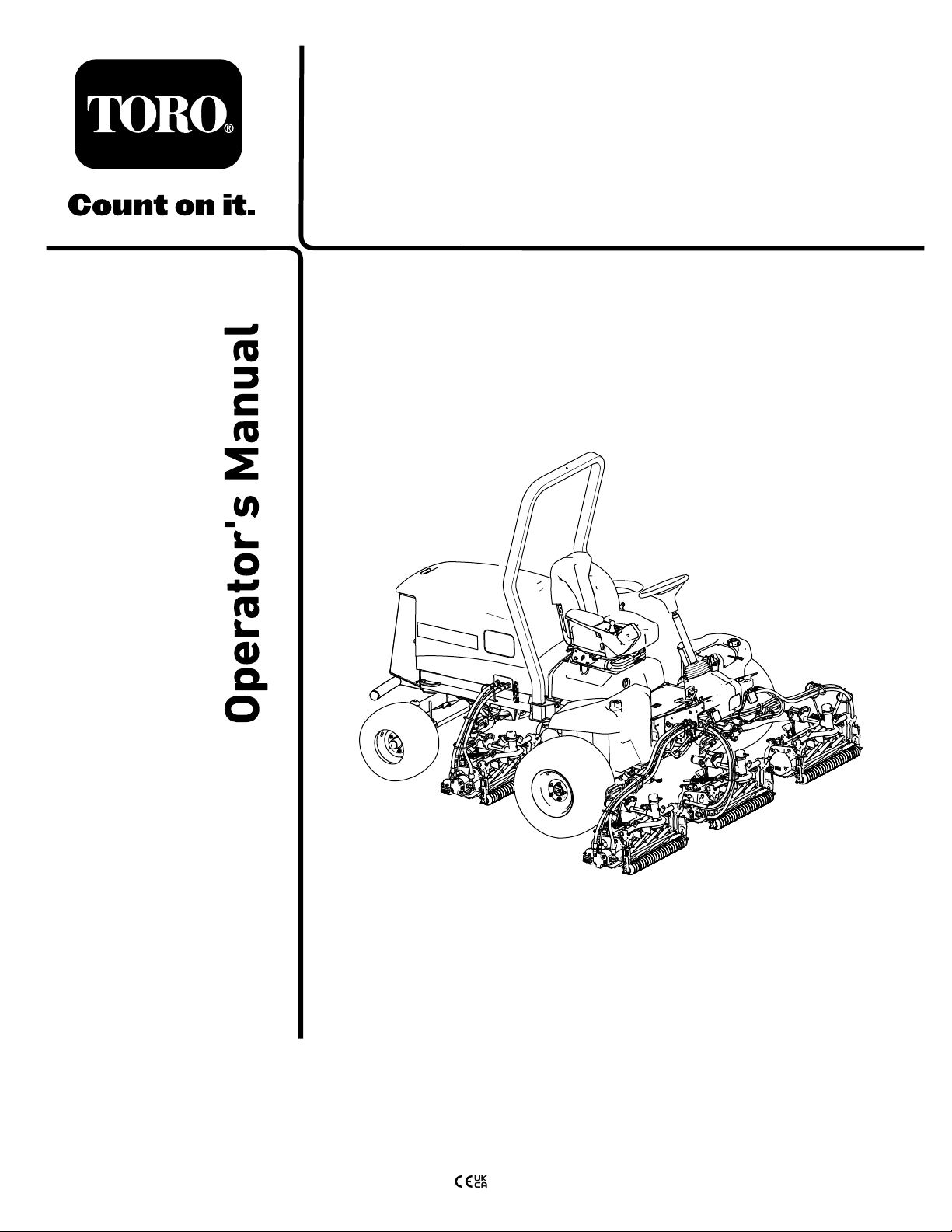
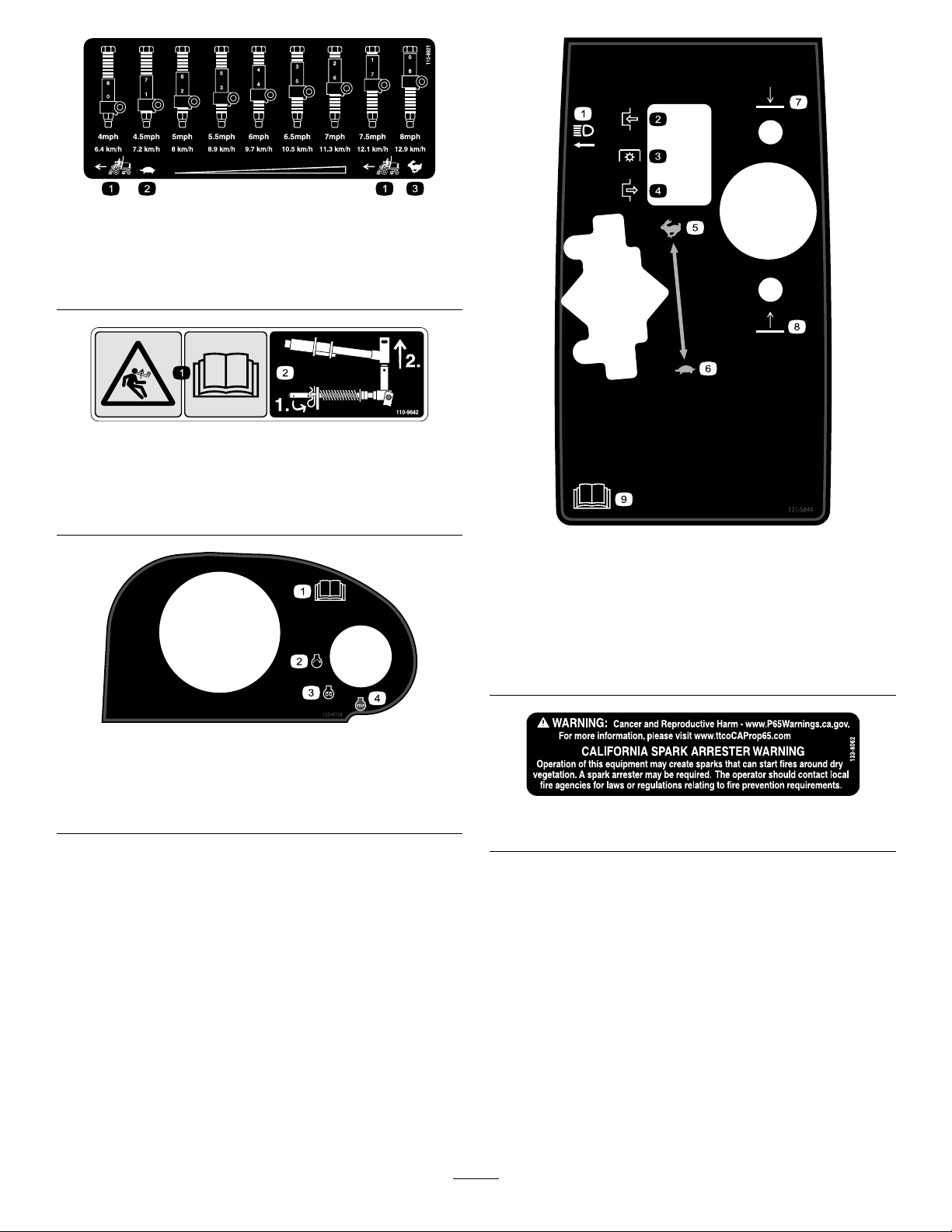
SafetyandInstructionalDecals..........................5
Setup......................................................................10
1PreparingtheMachine...................................10
2AdjustingtheControl-ArmPosition..................11
3InstallingtheCuttingUnits...............................11
4UsingtheCutting-UnitKickstand....................19
5InstallingtheCEHoodLock...........................19
6ApplyingtheCEDecals.................................21
ProductOverview...................................................22
Controls...........................................................22
SeatControls................................................24
UsingtheMenus...........................................25
Specications..................................................28
Attachments/Accessories.................................28
BeforeOperation.................................................29
BeforeOperationSafety...................................29
FuelSpecication.............................................29
FuelTankCapacity...........................................30
AddingFuel......................................................30
PerformingDailyMaintenance..........................30
CheckingtheInterlockSwitches.......................30
DuringOperation.................................................31
DuringOperationSafety...................................31
StartingtheEngine...........................................32
HydraulicFilter-RestrictionIndicator.................32
ShuttingOfftheEngine.....................................32
AdjustingtheTurf-Compensation
Spring...........................................................32
AdjustingtheLift-ArmCounterbalance.............33
AdjustingtheLift-ArmTurnaround
Position.........................................................33
SettingtheReelSpeed.....................................34
UnderstandingtheDiagnosticLight..................35
OperatingTips.................................................35
AfterOperation....................................................36
AfterOperationSafety......................................36
Tie-DownPointLocations.................................36
HaulingtheMachine.........................................36
PushingorTowingtheMachine........................36
Maintenance...........................................................38
MaintenanceSafety..........................................38
RecommendedMaintenanceSchedule(s)...........38
DailyMaintenanceChecklist.............................40
Pre-MaintenanceProcedures..............................41
PreparingforMaintenance...............................41
OpeningtheHood............................................41
ClosingtheHood..............................................41
OpeningtheScreen..........................................41
ClosingtheScreen...........................................42
TiltingtheSeat..................................................42
LoweringtheSeat.............................................42
JackingPointLocations....................................43
Lubrication..........................................................43
GreasingtheBearingsandBushings................43
EngineMaintenance...........................................45
EngineSafety...................................................45
CheckingtheAirFilter.......................................45
ServicingtheAirCleaner..................................45
ResettingtheAirFilterServiceIndicator............46
OilSpecication................................................46
CheckingtheLeveloftheEngineOil.................46
CrankcaseOilCapacity....................................47
ChangingtheEngineOilandFilter....................47
FuelSystemMaintenance...................................48
DrainingWaterfromtheFuel-Water
Separator......................................................48
ReplacingtheWater-SeparatorFilter................48
BleedingtheFuelSystem.................................49
CheckingtheFuelLinesand
Connections..................................................49
DrainingtheFuelT ank......................................49
CleaningtheFuel-PickupTubeScreen.............49
ElectricalSystemMaintenance...........................52
ElectricalSystemSafety...................................52
DisconnectingtheBattery.................................52
ConnectingtheBattery.....................................53
ChargingtheBattery.........................................53
ServicingtheBattery.........................................53
ReplacingaFuse-BlockFuse...........................53
ReplacingtheTelematicFuse...........................54
ReplacingtheTECControllerFuse...................54
DriveSystemMaintenance..................................55
CheckingtheTireAirPressure..........................55
CheckingtheT orqueoftheWheel
Nuts..............................................................55
AdjustingtheTractionDriveforNeutral.............55
CheckingtheRear-WheelAlignment................56
AdjustingtheRearWheelT oe-in.......................56
CoolingSystemMaintenance..............................57
CoolingSystemSafety.....................................57
CoolantSpecication........................................57
CheckingtheCoolantLevel..............................58
RemovingDebrisfromtheCooling
System..........................................................58
BrakeMaintenance.............................................59
AdjustingtheParkingBrakes............................59
AdjustingtheParking-BrakeLatch....................60
BeltMaintenance................................................61
TensioningtheAlternatorBelt...........................61
HydraulicSystemMaintenance...........................62
HydraulicSystemSafety...................................62
HydraulicFluidSpecications...........................62
CheckingtheHydraulic-FluidLevel...................62
CheckingtheHydraulicLinesand
Hoses............................................................63
ReplacingtheHydraulicFilters.........................63
HydraulicFluidCapacity...................................64
ChangingtheHydraulicFluid............................64
CuttingUnitSystemMaintenance........................65
BladeSafety.....................................................65
CheckingtheReel-to-BedknifeContact............65
BacklappingtheCuttingUnits...........................65
3

ChassisMaintenance...........................................67
InspectingtheSeatBelt....................................67
ExtendedChassisMaintenance...........................68
ChassisandEngine..........................................68
Cleaning..............................................................68
WashingtheMachine.......................................68
Storage...................................................................69
StorageSafety..................................................69
PreparingtheTractionUnit...............................69
PreparingtheEngine........................................69
StoringtheBattery............................................69
Safety
Thismachinehasbeendesignedinaccordance
withENISO5395(whenyoucompletethesetup
procedures)andANSIB71.4-2017.
GeneralSafety
Thisproductiscapableofamputatinghandsandfeet
andofthrowingobjects.
•Readandunderstandthecontentsofthis
Operator’sManualbeforestartingtheengine.
•Useyourfullattentionwhileoperatingthe
machine.Donotengageinanyactivitythat
causesdistractions;otherwise,injuryorproperty
damagemayoccur.
•Donotputyourhandsorfeetnearmoving
componentsofthemachine.
•Donotoperatethemachinewithoutallguards
andothersafetyprotectivedevicesinplaceand
functioningproperlyonthemachine.
•Keepbystandersandchildrenoutoftheoperating
area.Neverallowchildrentooperatethemachine.
•Shutofftheengine,removethekey,andwait
forallmovementtostopbeforeyouleavethe
operator’sposition.Allowthemachinetocool
beforeadjusting,servicing,cleaning,orstoringit.
Improperlyusingormaintainingthismachinecan
resultininjury.Toreducethepotentialforinjury,
complywiththesesafetyinstructionsandalways
payattentiontothesafety-alertsymbol,which
meansCaution,Warning,orDanger—personalsafety
instruction.Failuretocomplywiththeseinstructions
mayresultinpersonalinjuryordeath.
4

SafetyandInstructionalDecals
Safetydecalsandinstructionsareeasilyvisibletotheoperatorandarelocatednearanyarea
ofpotentialdanger.Replaceanydecalthatisdamagedormissing.
decalbatterysymbols
BatterySymbols
Someorallofthesesymbolsareonyourbattery.
1.Explosionhazard6.Keepbystandersaway
fromthebattery.
2.Nore,opename,or
smoking
7.Weareyeprotection;
explosivegasescan
causeblindnessandother
injuries.
3.Causticliquid/chemical
burnhazard
8.Batteryacidcancause
blindnessorsevereburns.
4.Weareyeprotection.9.Flusheyesimmediately
withwaterandgetmedical
helpfast.
5.ReadtheOperator's
Manual.
10.Containslead;donot
discard
decal93-6689
93-6689
1.Warning—donotcarrypassengers.
decal93-6696
93–6696
1.Storedenergyhazard—readtheOperator'sManual.
decal93-7272
93-7272
1.Cutting/dismembermenthazard;fan—stayawayfrom
movingparts.
decal106-6754
106-6754
1.Warning—donottouchthehotsurface.
2.Cutting/dismembermenthazard,fan;entanglementhazard,
belt—stayawayfrommovingparts.
decal106-6755
106-6755
1.Enginecoolantunder
pressure.
3.Warning—donottouchthe
hotsurface.
2.Explosionhazard—read
theOperator'sManual.
4.Warning—readthe
Operator'sManual.
decal110-0986
110-0986
1.Pressthebrakepedalandparkingbrakepedaltosetthe
parkingbrake.
2.Pressthebrakepedaltoapplythebrake.
3.Pressthetractionpedaltomovethemachineforward.
4.Reelenabledmode
5.Transportmode
5

decal110-8921
110-8921
1.Tractionunitspeed
2.Slow
3.Fast
decal110-9642
110-9642
1.Storedenergyhazard—readtheOperator'sManual.
2.Movethecotterpintotheholeclosesttotherodbracket
andthenremovetheliftarmandpivotyoke.
decal120-4158
120–4158
1.ReadtheOperator’s
Manual.
3.Engine—preheat
2.Engine—start4.Engine—stop
decal121-5644
121–5644
1.Lightswitch6.Slow
2.Engage7.Lower
3.Powertake-off8.Raise
4.Disengage9.ReadtheOperator’s
Manual.
5.Fast
decal133-8062
133-8062
6

decal145-5261
145-5261
1.Readthe
Operator's
Manualforfuse
information.
4.Electric7.TECcontroller
2.Powerpoint(12
V)
5.Enginestart8.TECcontroller
3.Headlights6.Airrideseat
suspension
(optional)
9.TECcontroller
decal133-2930
133-2930
1.Warning—donotoperatethismachineunlessyouaretrained.4.Tippinghazard—driveslowlywhenturning;donotturnsharply
whiletravelingfast;onlydriveonslopeswiththecuttingunits
lowered;alwayswearaseatbelt.
2.Warning—wearhearingprotection.5.Warning—donotparkonslopes;engagetheparkingbrake,
lowerthecuttingunits,shutofftheengine,andremovethe
ignitionkeybeforeleavingthemachine.
3.Thrownobjecthazard—keepbystandersoutoftheoperating
area.
6.Warning—readtheOperator'sManual;donottowthe
machine.
7

CEMachines
decal133-2931
133-2931
Note:Thismachinecomplieswiththeindustrystandardstabilitytestinthestaticlateralandlongitudinaltestswiththemaximum
recommendedslopeindicatedonthedecal.ReviewtheinstructionsforoperatingthemachineonslopesintheOperator’sManualas
wellastheconditionsinwhichyouwouldoperatethemachinetodeterminewhetheryoucanoperatethemachineintheconditions
onthatdayandatthatsite.Changesintheterraincanresultinachangeinslopeoperationforthemachine.Ifpossible,keepthe
cuttingunitsloweredtothegroundwhileoperatingthemachineonslopes.Raisingthecuttingunitswhileoperatingonslopescan
causethemachinetobecomeunstable.
1.Warning—readtheOperator'sManual;donotoperatethis
machineunlessyouaretrained.
4.Tippinghazard—donotdriveacrossordownslopesgreater
than15°;onlydriveonslopeswiththecuttingunitslowered;
alwayswearaseatbelt.
2.Warning—wearhearingprotection.5.Warning—donotparkonslopes;engagetheparkingbrake,
lowerthecuttingunits,shutofftheengine,andremovethe
ignitionkeybeforeleavingthemachine.
3.Thrownobjecthazard—keepbystandersaway.6.Warning—readtheOperator'sManual;donottowthe
machine.
8

decal136-3721
136-3721
1.ReadtheOperator’s
Manualforlubrication
information.
6.Engineairlter11.Enginecoolant16.Fluids
2.Brakefunctions7.Engineoil12.Engineoillevel17.Capacity
3.Checkevery8hours.8.Fanbelt13.Fuel18.Fluidinterval(hours)
4.Hydraulicuid9.Battery14.ReadtheOperator’s
Manual.
19.Filterinterval(hours)
5.Tirepressure10.Radiatorscreen15.Fuel/Waterseparator
9

Setup
LooseParts
Usethechartbelowtoverifythatallpartshavebeenshipped.
ProcedureDescriptionQty.Use
1Nopartsrequired–Preparethemachine.
2Nopartsrequired–Adjustthecontrol-armposition.
Rightfronthoseguide1
3Leftfronthoseguide1Installthecuttingunits.
4Cutting-unitkickstand1Installthecutting-unitkickstand.
Hoodlock,seal,andjamnut1
5Washer1InstalltheCEhoodlock.
CEdecal1
Productionyeardecal1
6Warningdecal1
ApplytheCEdecals.
MediaandAdditionalParts
DescriptionQty.Use
Operator'sManual1Readthemanualsbeforeoperatingthemachine.
Engineowner’smanual1Usethemanualtoreferenceengineinformation.
DeclarationofConformity1Thisdocumentindicatesconformitywithcertainstandards.
Operatortrainingmaterial1Reviewthetrainingmaterialbeforeoperatingthemachine.
Note:Determinetheleftandrightsidesofthe
machinefromthenormaloperatingposition.
1
PreparingtheMachine
NoPartsRequired
Procedure
1.Parkthemachineonalevelsurface,lowerthe
cuttingunits,andengagetheparkingbrake.
2.Shutofftheengine,removethekey,andwaitfor
allmovingpartstostop.
3.Checkthetireairpressurebeforeuse;referto
CheckingtheTireAirPressure(page55).
Note:Thetiresareoverinatedforshipping.
Adjustthetireairpressurebeforeoperatingthe
machine.
4.Checkthehydraulic-uidlevel;refertoChecking
theHydraulic-FluidLevel(page62).
5.Greasethemachine;refertoGreasingthe
BearingsandBushings(page43).
Important:Failuretoproperlygreasethe
machinewillresultinprematurefailureof
criticalparts.
6.Openthehoodandcheckthecoolantlevel;refer
toCheckingtheCoolantLevel(page58).
7.Checktheleveloftheengine-oillevel,andclose
andlatchthehood;refertoCheckingtheLevel
oftheEngineOil(page46).
Note:Theengineshipswithoilinthe
crankcase;however,checktheoillevelbefore
andaftertheengineisrststarted.
10

2
AdjustingtheControl-Arm
Position
NoPartsRequired
Procedure
Youcanadjustthecontrol-armpositionyourcomfort.
1.Loosenthe2boltssecuringthecontrolarmto
theretainingbracket(Figure3).
g004152
Figure3
1.Controlarm3.Bolts(2)
2.Retainingbrackets
2.Rotatethecontrolarmtothedesiredposition
andtightenthe2bolts.
3
InstallingtheCuttingUnits
Partsneededforthisprocedure:
1Rightfronthoseguide
1Leftfronthoseguide
PreparingtheMachine
1.Removethereelmotorsfromtheshipping
brackets.
2.Removeanddiscardtheshippingbrackets.
3.Ateachcuttingunitliftarm,removethelynchpin
thatsecuresthecaptotheliftarmpivotyoke,
andremovethecap(Figure4).
g003975
Figure4
1.Lynchpin2.Cap
PreparingtheCuttingUnits
1.Removethecuttingunitsfromthecartons.
2.Assembleandadjustasdescribedinthecutting
unitOperator'sManual.
3.Makesurethatthecounterweight(Figure5)is
installedattheproperendofthecuttingunitas
describedinthecuttingunitOperator'sManual.
11

g003320
Figure5
1.Counterweight
PositioningtheTurfCompensating
SpringandInstallingtheHose
Guide
CuttingUnits4
g375671
Figure6
1.Cuttingunit15.Cuttingunit5
2.Cuttingunit26.Reelmotor
3.Cuttingunit37.Weight
4.Cuttingunit4
1.Ifthehairpinisinstalledintherearholeofthe
compensation-springrod—removethehairpin
andinsertitintheholenexttothebracket
(Figure17).
g375689
Figure7
1.Hairpin
2.Removethe2angelocknuts(3/8inch)and2
carriagebolts(3/8x1-1/4inches)thatsecure
theturf-compensatorbrackettothecutting-unit
frame(Figure18).
g375690
Figure8
1.Carriagebolt(3/8x1-1/4
inches)
3.Flangelocknut(3/8inch)
2.Turf-compensatorbracket
3.Removetheangelocknut(3/8inch)that
securesthecapscrewoftheturfcompensation
springtotherighttabofthecarrierframe,
andremovethecompensationspringfromthe
cuttingunit(Figure19).
Note:Donotremovetheangeserratednut
fromthecapscrew.
12

g375691
Figure9
1.Capscrew3.Flangelocknut(3/8inch)
2.Righttab(Carrierframe)
4.Assemblethecapscrewoftheturfcompensation
springtotherighttabofthecarrierframe(Figure
20)withtheangelocknut(3/8inch).
g375694
Figure10
1.Flangelocknut(3/8inch)3.Capscrew
2.Righttab(Carrierframe)
5.Alignthestudsofthelefthoseguidewith
theholesinthecutting-unitframeandthe
turf-compensatorbracket(Figure21).
Note:Thesupportloopofthehoseguidealigns
towardthecenterlineofthemachine.
g375687
Figure11
1.Turf-compensatorbracket3.Stud(hoseguide)
2.Flangelocknut(3/8inch)4.Inboard
6.Assemblethehoseguideandturf-compensator
brackettothecutting-unitframewiththe2ange
locknuts(3/8inch).
7.T orquethelocknutsandboltsto37to45N∙m
(27to33ft-lb).
InstallingtheHoseGuide
CuttingUnits5
g375672
Figure12
1.Cuttingunit15.Cuttingunit5
2.Cuttingunit26.Reelmotor
3.Cuttingunit37.Weight
4.Cuttingunit4
1.Ifthehairpinisinstalledintherearholeofthe
compensation-springrod—removethehairpin
andinsertitintheholenexttothebracket
(Figure12).
13

g375689
Figure13
1.Hairpin
2.Removethe2angelocknuts(3/8inch)and2
carriagebolts(3/8x1-1/4inches)thatsecure
theturf-compensatorbrackettothecutting-unit
frame(Figure14).
g375690
Figure14
1.Carriagebolt(3/8x1-1/4
inches)
3.Flangelocknut(3/8inch)
2.Turf-compensatorbracket
3.Alignthestudsoftherighthoseguidewith
theholesinthecutting-unitframeandthe
turf-compensatorbracket(Figure15).
Note:Ensurethatthesupportloopofthe
hoseguidealignstowardthecenterlineofthe
machine.
g375688
Figure15
1.Stud(hoseguide)3.Flangelocknut(3/8inch)
2.Turf-compensatorbracket4.Inboard
4.Assemblethehoseguideandturf-compensator
brackettothecutting-unitframewiththe2ange
locknuts(3/8inch).
5.T orquethelocknutsto37to45N∙m(27to33
ft-lb).
PositioningtheTurfCompensating
Spring
CuttingUnit2
g379514
Figure16
1.Cuttingunit15.Cuttingunit5
2.Cuttingunit26.Reelmotor
3.Cuttingunit37.Weight
4.Cuttingunit4
1.Ifthehairpinisinstalledintherearholeofthe
compensation-springrod—removethehairpin
andinsertitintheholenexttothebracket
(Figure17).
14

g375689
Figure17
1.Hairpin
2.Removethe2angelocknuts(3/8inch)and2
carriagebolts(3/8x1-1/4inches)thatsecure
theturf-compensatorbrackettothecutting-unit
frame(Figure18).
g375690
Figure18
1.Carriagebolt(3/8x1-1/4
inches)
3.Flangelocknut(3/8inch)
2.Turf-compensatorbracket
3.Removetheangelocknut(3/8inch)that
securesthecapscrewoftheturfcompensation
springtotherighttabofthecarrierframe,
andremovethecompensationspringfromthe
cuttingunit(Figure19).
Note:Donotremovetheangeserratednut
fromthecapscrew.
g375691
Figure19
1.Capscrew3.Flangelocknut(3/8inch)
2.Righttab(Carrierframe)
4.Assemblethecapscrewoftheturfcompensation
springtotherighttabofthecarrierframe(Figure
20)withtheangelocknut(3/8inch).
g375694
Figure20
1.Flangelocknut(3/8inch)3.Capscrew
2.Righttab(Carrierframe)
5.Aligntheholesintheturf-compensatorbracket
withtheholesinthecutting-unitframe(Figure
21).
Note:Thesupportloopofthehoseguidealigns
towardthecenterlineofthemachine.
15

g378789
Figure21
1.Turf-compensatorbracket3.Flangelocknut(3/8inch)
2.Carriagebolt(3/8x1-1/4
inches)
4.Inboard
6.Assembletheturf-compensatorbrackettothe
cutting-unitframewiththe2carriagebolts(3/8x
1-1/4inches)and2angelocknuts(3/8inch).
7.T orquethelocknutsandboltsto37to45N∙m
(27to33ft-lb).
InstallingtheKickstand
Foreachcuttingunit,securethekickstandtothe
chainbracketwiththesnapperpin(Figure22).
g004144
Figure22
1.Chainbracket3.Cutting-unitkickstand
2.Snapperpin
InstallingtheFrontCuttingUnits
totheLiftArms
1.Slideacuttingunitundertheliftarm(Figure23).
g375274
Figure23
1.Cap3.Lift-armyoke
2.Snapperpin4.Carrierframeshaft
2.Assemblethelift-armyokeontothecarrier
frameshaft.
3.Assemblethecaptothepivot-armshaft,and
aligntheholesinthecarrierframeshaft,pivot
armshaft,andcap.
4.Securethecapandthecarrier-frameshaftto
thelift-armyokewiththesnapperpin.
LockingtheCutting-UnitPivotforCutting
GrassonaHillSide—Lockthecutting-unit
pivotstopreventthecuttingunitsfromrotating
downhillwhencuttingacrossthefaceofahill.
Usetheholeinthelift-armpivotshaft(Figure
24)tolockthecuttingunit.Usetheslotfora
steeringcuttingunit.
g375251
Figure24
1.Snap-pinpositions3.Slot(lift-armpivotshaft)
2.Hole(lift-armpivotshaft)
16

InstallingtheRearCuttingUnitsto
theLiftArms
CuttingUnitsadjustedfora1.2cm(3/4inch)
orHigherHeightofCut
1.Slideacuttingunitundertheliftarm(Figure25).
g375252
Figure25
1.Cap3.Lift-armyoke
2.Snapperpin4.Carrierframeshaft
2.Assemblethelift-armyokeontothecarrier
frameshaft.
3.Assemblethecaptothepivot-armshaft,and
aligntheholesinthecarrierframeshaft,pivot
armshaft,andcap.
4.Securethepivotarmshaftandcaptothecarrier
frameshaftwiththesnapperpin.
LockingtheCutting-UnitPivotforCutting
GrassonaHillSide—Lockthecutting-unit
pivotstopreventthecuttingunitsfromrotating
downhillwhencuttingacrossthefaceofahill.
Usetheholeinthelift-armpivotshaft(Figure
25)tolockthecuttingunit.Usetheslotfora
steeringcuttingunit.
g375251
Figure26
1.Snap-pinpositions3.Slot(lift-armpivotshaft)
2.Hole(lift-armpivotshaft)
5.Repeatsteps1and2fortheotherrearcutting
unit.
InstallingtheRearCuttingUnitsto
theLiftArms
CuttingUnitsadjustedfora1.2cm(3/4inch)
orLowerHeightofCut
1.Removethelynchpinandwashersecuringthe
tothelift-armpivotshafttotheliftarm,andslide
thepivotshaftoutoftheliftarm(Figure27).
g375236
Figure27
1.Lift-armpivotshaft4.3.Liftarm(rearcuttingunit)
2.Lift-armpivotshaft4.Washer
2.Assemblethelift-armyokeontothecarrier
frameshaft(Figure28).
17

g375237
Figure28
1.Cap3.Lift-armyoke
2.Snapperpin4.Carrierframeshaft
3.Assemblethecaptothepivot-armshaft,and
aligntheholesinthecarrierframeshaft,pivot
armshaft,andcap.
4.Securethepivotarmshaftandcaptothecarrier
frameshaftwiththesnapperpin.
LockingtheCutting-UnitPivotforCutting
GrassonaHillSide—Lockthecutting-unit
pivotstopreventthecuttingunitsfromrotating
downhillwhencuttingacrossthefaceofahill.
Usetheholeinthelift-armpivotshaft(Figure
29)tolockthecuttingunit.Usetheslotfora
steeringcuttingunit.
g375251
Figure29
1.Snap-pinpositions3.Slot(lift-armpivotshaft)
2.Hole(lift-armpivotshaft)
5.Slideacuttingunitundertheliftarm(Figure30).
g375239
Figure30
1.Lynchpin3.Liftarm
2.Lift-armshaft4.Washer
6.Insertthelift-armshaftintotheliftarm,and
secureshafttothearmwiththelynchpinand
washer.
7.Repeatsteps1through6fortheotherrear
cuttingunit.
InstallingtheCuttingUnitLift-Arm
Chains
Securethelift-armchaintothechainbracketwiththe
snapperpin(Figure31).
Note:Usethenumberofchainlinksdescribedinthe
cuttingunitOperator'sManual.
g003948
Figure31
1.Lift-armchain3.Snapperpin
2.Chainbracket
InstallingtheReelMotors
1.Coatthesplineshaftofthereelmotorwithclean
grease.
2.OilthereelmotorO-ringandinstallitontothe
motorange.
3.Installthemotorbyrotatingitclockwisesothat
themotorangesclearthebolts(Figure32).
18

g004127
Figure32
1.Reel-drivemotor2.Mountingbolts
4.Rotatethemotorcounterclockwiseuntilthe
angesencirclethebolts,andthentightenthe
bolts.
Important:Makesurethatthereelmotor
hosesarenottwisted,kinked,oratriskof
beingpinched.
5.T orquethemountingboltsto(27to33ft-lb).
4
UsingtheCutting-Unit
Kickstand
Partsneededforthisprocedure:
1Cutting-unitkickstand
Procedure
Wheneveryoumusttipthecuttingunittoexposethe
bedknife/reel,propuptherearofthecuttingunitwith
thekickstandtomakesurethatthenutsontheback
endofthebedbar-adjustingscrewsarenotrestingon
theworksurface(Figure33).
g003985
Figure33
1.Cutting-unitkickstand
Securethekickstandtothechainbracketwiththe
snapperpin(Figure34).
g004144
Figure34
1.Chainbracket3.Cutting-unitkickstand
2.Snapperpin
19

5
InstallingtheCEHoodLock
Partsneededforthisprocedure:
1Hoodlock,seal,andjamnut
1Washer
Procedure
1.Unlatchandraisethehood.
2.Removetherubbergrommetfromtheholein
theleftsideofthehood(Figure35).
g004143
Figure35
1.Rubbergrommet
3.Ensurethatthesealisassembledtothehood
lock(Figure36).
g375326
Figure36
1.Hoodlatch3.Seal
2.Nut4.Washer
4.Removethenutfromthelock.
5.Outsidethehood,insertthehookendofthe
latchthroughtheholeinthehood.
Note:Thesealisalignedtotheoutsideofthe
hood.
6.Insidethehood,Securethelocktothehood
withthewasherandnut.
7.Closethehood,andusetheenclosedhood-latch
keytocheckthatthehookofthelockengages
theframecatchwhenlocked.
20
This manual suits for next models
1
Table of contents
Other Toro Lawn And Garden Equipment manuals

Toro
Toro 44922 User manual

Toro
Toro 30370 User manual

Toro
Toro Bullseye QuickGroom 700 User manual

Toro
Toro TXL 2000 User manual

Toro
Toro 121-5132 User manual

Toro
Toro 41323 User manual

Toro
Toro 22473 User manual

Toro
Toro 22472 User manual

Toro
Toro Bullseye QuickGroom 550 User manual

Toro
Toro 29521 User manual

Toro
Toro 03662 User manual

Toro
Toro ECx User manual

Toro
Toro Greens Aerator User manual

Toro
Toro 58630 User manual

Toro
Toro Ultra Sonic Boom 41219 User manual

Toro
Toro procore sr54 User manual

Toro
Toro 39514 User manual

Toro
Toro Groundsmaster 7200 Series User manual

Toro
Toro ProCore 648 User manual

Toro
Toro 58630 User manual