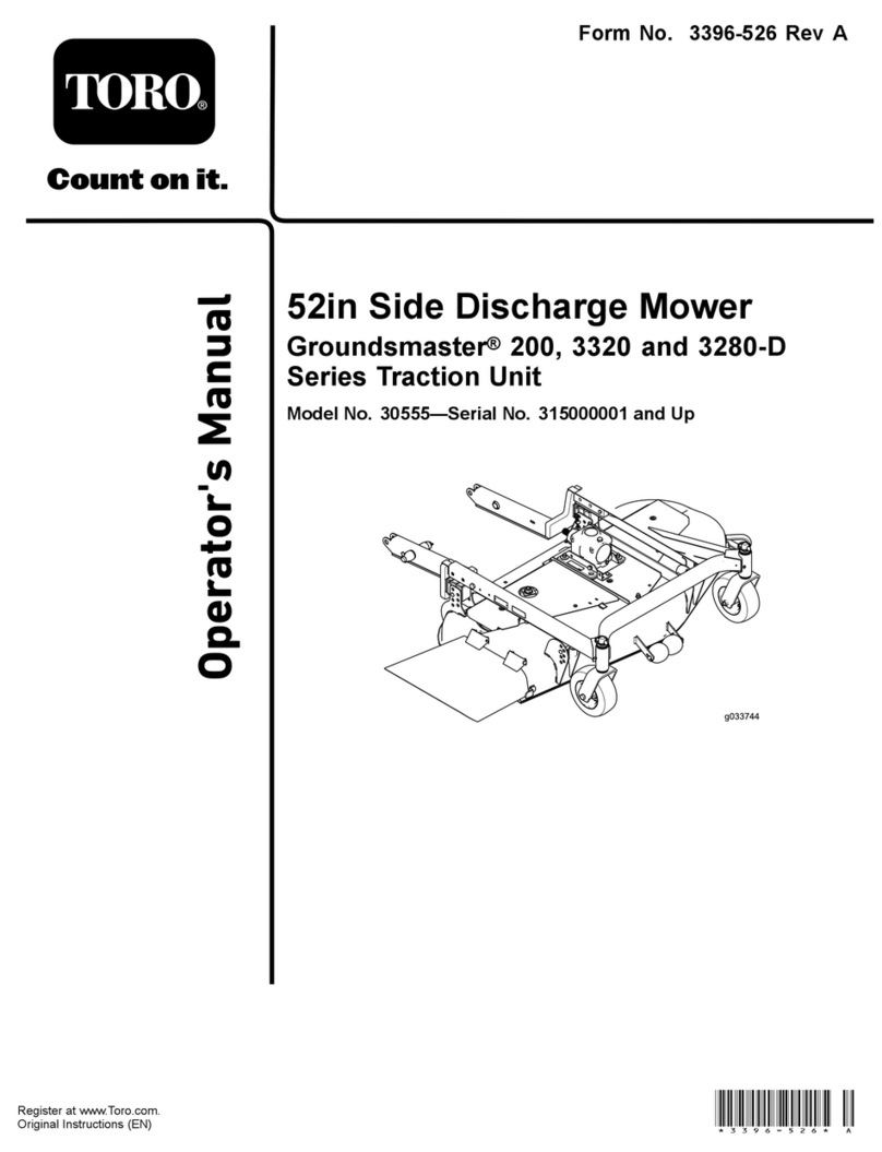
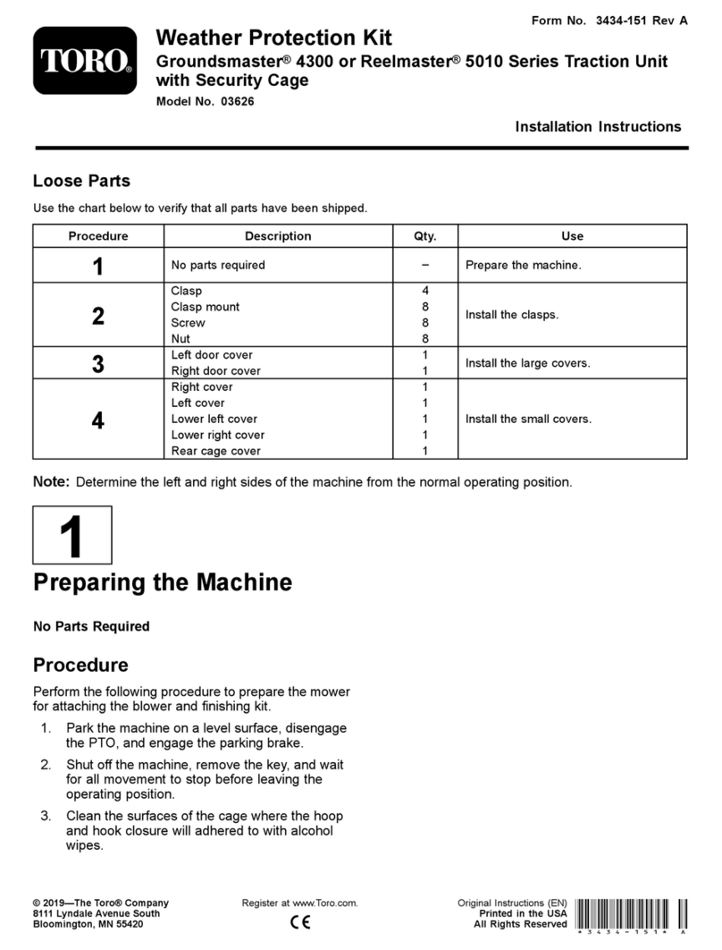
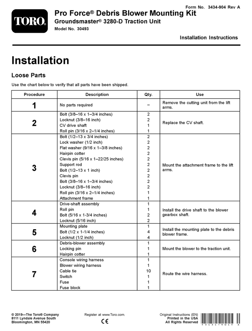
Toro 02861 User manual

FormNo.3410-508RevA
ElectricLiftKit
TM5490/TM7490TrailedMowers
ModelNo.02861—SerialNo.400000000andUp
InstallationInstructions
WARNING
CALIFORNIA
Proposition65Warning
ThisproductcontainsachemicalorchemicalsknowntotheStateofCaliforniato
causecancer,birthdefects,orreproductiveharm.
ThisproductcomplieswithallrelevantEuropeandirectives.Fordetails,pleaseseetheDeclarationofIncorporation(DOI)at
thebackofthispublication.
Safety
Beforeinstallingthekit:
•ReadthemachineOperator'sManualandtheseInstallation
Instructions.
•Alwaysweareyeprotection.
Important:Alwaysseekprofessionaladvicefromyour
localauthorizeddealerif,afterstudyingthis,youare
unsurehowtoinstallthiskit.
SafetyandInstructionalDecals
Safetydecalsandinstructionsareeasilyvisibletotheoperatorandarelocatednearanyareaofpotential
danger.Replaceanydecalthatisdamagedormissing.
decal111-1777
111-1777
1.Cuttingunitrotationcontrol4.Reverserotation7.Rightwingarmliftcontrol
2.Forwardrotation5.Leftwingarmliftcontrol8.Overrideliftcontrol
3.Disengagecuttingcylinder6.Center3or5armliftcontrol9.Emergencystop
©2016—TheToro®Company
8111LyndaleAvenueSouth
Bloomington,MN55420
Registeratwww.T oro.com.OriginalInstructions(EN)
PrintedintheUK
AllRightsReserved*3410-508*A

Installation
LooseParts
Usethechartbelowtoverifythatallpartshavebeenshipped.
ProcedureDescriptionQty.Use
Control-boxbracket1
Setscrew(8x25mm)2
Washer(8mm)10
Locknut(8mm)5
Electriccontrolbox1
Self-tappingscrews(6x12mm)4
Umbilicalcableassembly1
Liftmanifold1
Solenoidvalve(closed)1
Solenoid1
Bondedseal(1/4inch)4
Adapter(1/4inchmalex1/4inchmale)3
Plug(1/4inchmale)1
Plug(3/8inchmale)2
Bondedseal(3/8inch)5
Adapter(3/8inchmalex3/8inchmale)3
Adapter(1/4inchmalex3/8inchmale)1
Checkvalve(3/8inch)1
Coupling(3/8inchmalex3/8inch
female)1
Elbow(3/8inchmalex3/8inchfemale)1
Tee(3/8inchmalex3/8inchfemalex
3/8inchmale)1
Crosstting(1/4inchmale)1
Elbow(1/4inchfemalex1/4inch
female)1
Bolt(8x75mm)2
Bolt(8x65mm)1
Hose(3/8inchx575mm)1
1
Hose(1/4inchx2.16m)1
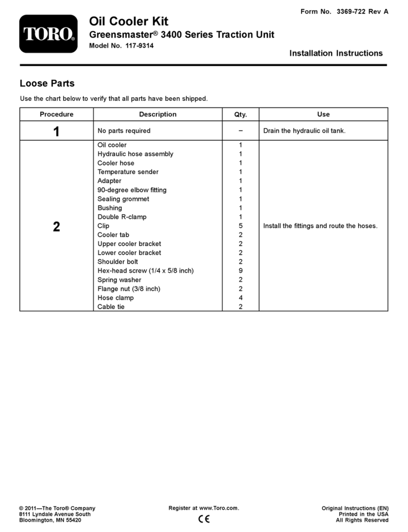
Installtheelectriccontrolbox.
2

ProcedureDescriptionQty.Use
Actuatorbracket1
Proximitysensor1
Proximity-sensorbracket1
Setscrew(6x25mm)2
Washer(6mm)4
Locknut(6mm)2
Capscrew(5x20mm)2
Washer(5mm)4
Locknut(5mm)2
Spacer1
Solenoidvalve(closed)1
Linebody1
Bondedseal(3/8inch)2
Adapter(1/4inchfemalex3/8inch
male)1
Bondedseal(1/4inch)1
Hose(1/4inchx380mm),90°xstraight1
Tee(1/4inchmalex1/4inchmalex1/4
inchfemale)1
Adapter(1/4inchmalex1/4inchmale),
1.4mmorice1
Cylinderrodspringpin1
Bush1
Washer(10mm)1
Valvecylinder1
Bondedseal(3/4inch)1
Adapter(1/4inchmalex3/4inchmale)1
Swiveltee(1/4inchfemale)1
Adapter(1/4inchmalex1/4inchmale),
0.8mmorice1
Hose(1/4inchx2.156m)1
Adapter(1/4inchmalex3/8inchmale)1
Splitpin1
Cabletie8
2
Hosetie(368x4.8mm)1
Installtherotaryvalvecylinder
assembly.
Remote-controlbox1
Remote-controlbracket2
Capscrew(8x25mm)4
Washer(8mm)8
Nut(8mm)4
3
Locknut(8mm)4
Installtheremotecontrolboxand
brackets.
Important:Donotdiscardanycomponentsthatareremoveduntiltheinstallationhasbeencompleted,assome
existingpartswillneedtobeusedforinstallingthekit.
3

1
InstallingtheElectricControl
Box
Partsneededforthisprocedure:
1Control-boxbracket
2Setscrew(8x25mm)
10Washer(8mm)
5Locknut(8mm)
1Electriccontrolbox
4Self-tappingscrews(6x12mm)
1Umbilicalcableassembly
1Liftmanifold
1Solenoidvalve(closed)
1Solenoid
4Bondedseal(1/4inch)
3Adapter(1/4inchmalex1/4inchmale)
1Plug(1/4inchmale)
2Plug(3/8inchmale)
5Bondedseal(3/8inch)
3Adapter(3/8inchmalex3/8inchmale)
1Adapter(1/4inchmalex3/8inchmale)
1Checkvalve(3/8inch)
1Coupling(3/8inchmalex3/8inchfemale)
1Elbow(3/8inchmalex3/8inchfemale)
1Tee(3/8inchmalex3/8inchfemalex3/8inchmale)
1Crosstting(1/4inchmale)
1Elbow(1/4inchfemalex1/4inchfemale)
2Bolt(8x75mm)
1Bolt(8x65mm)
1Hose(3/8inchx575mm)
1Hose(1/4inchx2.16m)
Procedure
1.Parkthemachineonalevelsurface,disengagethe
tractorPTO,andengagetheparkingbrakeofthe
tractorandtheparkingbrakeofthetrailedmower.
2.Lowerthecuttingunitstotheground.
3.Turnoffthetractorengineandremovetheignitionkey.
4.Removeallcontrolcablesfromtheliftandoverride
controlvalvesFigure1.
5.Removethenutsandboltssecuringtheexisting
control-leverbrackettothemachine(Figure1).
g028993
Figure1
1.Controllevers3.Controlcables
2.Control-leverbracket4.Bolts(nutsnotshown)
6.Removeanddiscardthecontrolleversandthebracket.
7.Disconnectallhoseconnectionstotheoverridevalve
(Figure2),andremovethehosethatconnectstothe
rearpump.
g025355
Figure2
1.Liftvalve2.Overridevalve
8.Disconnectallhoseconnectionstotheliftcontrol
valve(Figure2).
9.Removetheliftcontrolvalveandtheoverridecontrol
valvefromthemachine.
10.Fastenthecontrol-boxbrackettotheexistinglift-valve
mountingbracketonthefrontofthechassisusing2
setscrews(8x25mm),4plainwashers(8mm),and2
locknuts(8mm);refertoFigure3.
4

g025356
Figure3
1.Setscrew(8x25mm),23.Washer(8mm),4
2.Control-boxbracket4.Locknut(8mm),2
11.Fastentheelectriccontrolboxtothebracketusing4
self-tappingscrews(6x12mm).
g025357
Figure4
1.Electriccontrolbox2.Self-tappingscrew(6x12
mm),4
12.Taketheumbilicalcableassemblyandidentifytheend
with2controlboxconnectors.Passthisendofthe
cablethroughthekeyhole-shapedholeatthefrontof
thebracketandsecureitwiththebacknutsprovided.
g025358
Figure5
1.Umbilicalcableassembly
13.Connectthe2umbilicalcableplugstotheelectric
controlbox,usingthelargecabletieprovided.
14.Assemblethelift-controlblockassemblywiththe
ttingsasshowninFigure6andFigure7.
6
5
7
1
2
45 45 31 G025630
g025630
Figure6
1.Bondedseal(1/4inch)5.Bondedseal(3/8inch)
2.Adapter(1/4inchmalex
1/4inchmale)
6.Adapter(3/8inchmalex
3/8inchmale)
3.Plug(1/4inchmale)7.Liftmanifold
4.Plug(3/8inchmale)
5

1
G025513
2345
g025513
Figure7
1.Crosstting(1/4inch
male)
4.Bondedseal(1/4inch)
2.Elbow(1/4inchfemalex
1/4inchfemale)
5.Liftmanifold
3.Adapter(1/4inchmalex
1/4inchmale)
15.Fastenthelift-controlblockassemblytothebracket
using2bolts(8x75mm),1bolt(8x65mm),6plain
washers(8mm),and3locknuts(8mm).
Note:Someofthesolenoidsmayneedtobeloosened
orremovedtogainaccesstotheboltholes.
1
G025408
3
3
5
2
4
3
3
g025408
Figure8
1.Bolts(8x75mm)4.Bolt(8x65mm)
2.Locknut(8mm)5.Locknuts(8mm)
3.Washers(8mm)
16.Connectthelifthosestotheirrelevantconnectorson
theliftcontrolblock.
Note:Somehoseswillrequirearrangingforneatness.
Wherenecessary,slackenthehosettingsateachend,
orientatetosuitandensurethatbothendsofthehose
ttingsaretightened.
1
7
G025409
23
8654
g025409
Figure9
1.Hose(1/4inchx2.16m),
totherotaryvalveatthe
rearofthemachine
5.Hose(existing),tothe
centerliftcylinder
2.Hose(existing),tothe
frontleftliftcylinder
6.Hose(existing),totheleft
wingliftcylinder
3.Hose(existing),tothe
frontrightliftcylinder
7.Hose(existing),tothe
frontmanifold
4.Hose(existing),totheright
wingliftcylinder
8.Hose(3/8inchx57.5cm),
totheliftpump
17.ReferringtoFigure10,assemblealinebody,asolenoid
valve,andasolenoid.Fitthecoupling,thebonded
seal,andtheelbowtoport1ofthelinebody.Fita
3/8inchbondedseal,a3/8inchmalex3/8inch
maleadapter,two3/8inchbondedseals,checkvalve,
and3/8x1/4inchmaleadaptertoport2oftheline
body.FittheassemblytotheteeonthePportofthe
liftcontrolblock.Fitthehosefromtheteetothelift
pump.Fitthehosefromtherotaryvalveattherearof
themachinetothecheckvalve.
Note:Ensurethatthearrowonthecheckvalvepoints
awayfromthelinebody.
6

g188311
Figure10
Somettingsnotshown
1.Solenoid7.Adapter(1/4inchmalex
3/8inchmale)
2.Solenoidvalve8.Coupling(3/8inchmalex
3/8inchfemale)
3.Linebody9.Elbow(3/8inchmalex3/8
inchfemale),90°
4.Bondedseal(3/8inch)10.Tee(3/8inchmalex3/8
inchfemalex3/8inch
male)
5.Adapter(3/8inchmalex
3/8inchmale)
11.Liftmanifold
6.Checkvalve(3/8inch)
18.Connecttheelectricalleadsfromtheelectriccontrol
boxtotherelevantsolenoids.
1
2
3
4
5
6
7
5
1
6
2
7
3
8
4
8
9
10
G025362
1112
g025362
Figure11
1.Rightwing(labeled2C)7.Labeled2F
2.Middle(labeled2B)8.Cutterreverserotation
(labeled1)
3.Leftwing(labeled2A)9.Tothesolenoidattherear
ofthemachine
4.Liftoverride(labeled3)10.Totheproximitysensor
5.Labeled2D11.Liftcontrolblock
6.Labeled2E12.Electriccontrolbox
2
InstallingtheRotaryValve
CylinderAssembly
Partsneededforthisprocedure:
1Actuatorbracket
1Proximitysensor
1Proximity-sensorbracket
2Setscrew(6x25mm)
4Washer(6mm)
2Locknut(6mm)
2Capscrew(5x20mm)
4Washer(5mm)
2Locknut(5mm)
1Spacer
1Solenoidvalve(closed)
1Linebody
2Bondedseal(3/8inch)
1Adapter(1/4inchfemalex3/8inchmale)
1Bondedseal(1/4inch)
1Hose(1/4inchx380mm),90°xstraight
1Tee(1/4inchmalex1/4inchmalex1/4inchfemale)
1Adapter(1/4inchmalex1/4inchmale),1.4mmorice
1Cylinderrodspringpin
1Bush
1Washer(10mm)
1Valvecylinder
1Bondedseal(3/4inch)
1Adapter(1/4inchmalex3/4inchmale)
1Swiveltee(1/4inchfemale)
1Adapter(1/4inchmalex1/4inchmale),0.8mmorice
1Hose(1/4inchx2.156m)
1Adapter(1/4inchmalex3/8inchmale)
1Splitpin
8Cabletie
1Hosetie(368x4.8mm)
Procedure
1.Attherearofthemachine,removetherearcoverto
gainaccesstotherotaryvalvecontrolsystem(Figure
12).
7

1
G025360
2
g025360
Figure12
1.Rearcover2.Bolts
2.Removetherotaryvalvecylinderassemblyand
disconnectthecylinderfeedhose.
1
G025361
2
g025361
Figure13
1.Rotaryvalvecylinder
assembly
2.Cylinderfeedhose
3.Removetheappropriatescrewsecuringtherotary
brackettotherotaryvalveasshowninFigure14.
1
9
13
12
11
14
2 3
456
1
8G025363
7
10
g025363
Figure14
1.Washer(6mm),48.Locknut(6mm)
2.Setscrew(6x25mm),29.Actuatorbracket
3.Spacer10.Washer(existing)
4.Proximitysensor11.Screw(existing)
5.Washer(5mm)12.Proximity-sensorbracket
6.Capscrew(5x20mm),213.Washer(5mm)
7.Backlaplever14.Locknut(5mm)
4.Assembletheactuatorbracketontotherotarybracket,
andsecureitusingtheoriginalscrewandwasher.
5.Mounttheproximitysensorandthespacerontothe
bracket.Fitthisassemblytotherotaryvalvemounting
bracketandsecureitwith2setscrews(6x25mm),4
washers(6mm)and2locknuts(6mm).
6.Operatethebacklapleverandadjustthepositionof
thesensorassemblysothatthegapbetweenthesensor
andtheactuatoris5mm.
7.Tightenallthefastenersonthesensorassembly.
8.Assemblethenewrotaryvalvecylinderwithanew
cylinderrodspringpin,bush,3/4inchbondedseal,
and3/4inchmalex1/4inchmaleadapter(Figure15).
Note:Usetheoriginalsprings.
8

12345
19
21
4
20
18 17 16 15
6
7
12
10
11
8
9
7
10
14
13
G025354
g025354
Figure15
1.Solenoid(12volt)13.Bush
2.Solenoidvalve(closed)14.Valvecylinder
3.Linebody15.Bondedseal(3/4inch)
4.Bondedseal(3/8inch)16.Adapter(1/4inchmalex
3/4inchmale)
5.Adapter(1/4inchfemalex
3/8inchmale)
17.Swiveltee(1/4inchfemale
x1/4inchfemalex1/4
inchfemale)
6.Bondedseal(1/4inch)18.Adapter(1/4inchmalex
1/4inchmale),0.8mm
orice
7.Hose(1/4inchx38cm),
90°xstraight
19.Hose(1/4inchx2.156m),
tothefrontsolenoidvalve
8.Tee(1/4inchmalex
1/4inchmalex1/4inch
female)
20.Adapter(1/4inchmalex
3/8inchmale)
9.Adapter(1/4inchmalex
1/4inchmale),1.4mm
orice
21.Splitpin
10.Spring(existing)22.Cableties(8),notshown
11.Cylinderrodspringpin23.Largehosetie(368x4.8
mm),notshown
12.Washer(10mm)
9.Removethebacklapreleaseleverfromtherearhole,
andinstallitintothefronthole(Figure16).
1
2
3
G025364
g025364
Figure16
1.Frontslot3.Fronthole
2.Rearhole
10.Fittherotaryvalvecylinderassemblyinthefrontslot
(Figure16),andsecureitusingtheoriginalboltand
slidebush.
11.Attachthecylindertotherotarybracketusingthe
washer(10mm)andthesplitpin.
12.Fitthe1/4inchfemaleteeandthe1/4inchmale
adapter(0.8mmorice)tothecylinderport,and
connectthehosefromthefrontsolenoidvalve.
13.Disconnectthehoseonthelower1/4inchportofthe
rearmanifold.Fita1/4inchmaleteetotheport,and
connectthehose.
14.Assemblealinebodywithasolenoidvalveand
solenoid.Fita3/8inchbondedsealanda3/8inchx
1/4inchmaleadapter(existing),toport1oftheline
body.Fita3/8inchbondedseal,a3/8inchx1/4inch
adapter,a1/4inchbondedseal,anda1/4inchmale
adapter(1.4mmorice)toport1ofthelinebody.
Connecttheassemblytothevalvecylinderlinebody.
15.Connectthehosetotheteeontherearmanifold.
Connecttheotherendtothettingsonthevalve
cylinderlinebody.
16.Runthecablesfromthecontrolboxtotherear
solenoidvalveandtheproximityswitchbracketalong
thecenterofthemachine(underthehydraulictank)to
therear.Connectthecablestothesolenoidandthe
switch,respectively.
17.Keeptherearsolenoidcableandtherearcylinderhose
tidybyusingthe8cabletiesandthelargehosetie(368
x4.8mm)tosecurethemtotheexistinghosesunder
thehydraulicoiltank.
18.Checkallthefastenersandhoseconnections,and
tightenthemasnecessary.
9
3
InstallingtheRemoteControl
BoxandBrackets
Partsneededforthisprocedure:
1Remote-controlbox
2Remote-controlbracket
4Capscrew(8x25mm)
8Washer(8mm)
4Nut(8mm)
4Locknut(8mm)
Procedure
1.Removeanddiscardthecontrolleversandthebracket.
2.Mount1remote-controlbracketonthemachine,as
shown.
76 5 24
G025406
8
321
g025406
Figure17
1.Nut(8mm),25.Locknut(8mm),2
2.Washer(8mm),46.Umbilicalcableassembly
3.Capscrew(8x25mm),27.Remote-controlbox
4.Remote-controlbracket8.Powercable
3.Mounttheotherbracketinasuitablelocationinthe
cabofthetractor.
Important:Refertotheinformationfrom
thetractormanufacturersothatthebracket
installationdoesnotcompromisethesafetyofthe
ROPS.
4.Connectthepowercableintothe12-voltsocketinthe
cabofthetractor.
10

ProductOverview
decal111-1777
Figure18
1.Cuttingunitrotationcontrol4.Reverserotation7.Rightwingarmliftcontrol
2.Forwardrotation5.Leftwingarmliftcontrol8.Overrideliftcontrol
3.Disengagecuttingcylinder6.Center3or5armliftcontrol9.Emergencystop
Controls
EmergencyStop
Thefollowingoccurswhenyouoperatetheemergencystop:
•Allcuttingunitdrivesaredisengaged.
•Allcuttingunitliftarmsarehydraulicallylockedatthe
positiontheywereinwhentheemergencystopbutton
waspressed.Theliftarmswillremaininthisposition
supportedsolelybythehydraulicsystem.
•Theelectricalcontrolsystemisdisabled.
Important:Ifanyofthesefunctionsdonothappen,
consultyourAuthorizedToroDistributorbeforeusing
themachine.
WARNING
Ifyoudonotlowerthecuttingunitstotheground
anddisengagethePTO,someonecouldbe
seriouslyinjured.
Lowerthecuttingunitstotheground,and
disengagethePTO.
OverrideLiftControl
Pushtheoverrideliftcontrolawaytolowerallcuttingunits
simultaneously.Pullitbackwardtoraisethecuttingunits
simultaneously.
Note:Thisfunctionwillonlyoperateoncuttingunitswhere
theindividualcontrolswitchesareinthedown/cutposition.
Thecuttingunitdrivedisengagesquicklywhentheoverride
controlswitchisoperatedtoraisethecuttingunits,ormoved
totheneutral(N)position.Thecuttingunitdriveengages
whenthecuttingunitisapproximately300to400mm
(11-13/16to15-11/16inches)abovegroundlevelwhenthe
overrideswitchisoperatedtolowerthecuttingunits.
Lift/LowerControlSwitches
Pushthelift/lowercontrolswitchesawaytolowerthe
cuttingunitsindependently.Thecuttingunitdriveengages
approximately300to400mm(11-13/16to15-11/16inches)
abovegroundlevel.Pullthelift/lowercontrolswitches
backwardtoraisethecuttingunitsindependently.
Note:Theliftlowercontrolswitcheswillonlyoperatewhen
theoverrideliftcontrolisinthedown/cutposition.
CutterRotationControl
Pushthecutterrotationcontrolawaytodrivethecuttingunits
intheforwardrotation.Pullthecutterrotationcontrolback
andholdittodrivethecuttingunitsinthereverserotation.
Thereversesettingisintendedforcuttingunitblockage
removalonlyandshouldnotbeusedforbacklapping.
Note:Thecutterrotationcontroloperatesonlywhenthe
overrideliftcontrolisinthedown/cutposition.Operate
itonlywhentheoverrideliftcontrolisinthedown/cut
position.
Todisengagedrivetoallcuttingunits,movethecutter
rotationcontroltotheOffposition,ormovetheoverridelift
controltotheNeutral(N)position,and/ordisengagethe
tractorPTO.Inanemergency,operatetheemergencystop
button.
11

PowerIndicatorLight
Whenthelightisilluminated,powerisbeingfedtothe
electricalcontrolbox.Iftheindicatorfailstolight,checkthe
electricalsupplyconnectiontothetractor.
Note:Whenthepowerindicatorlightisnotilluminated,the
electricliftcontrolsystemisinoperative.
HourMeter
Thehourmeterislocatedintheelectricalcontrolboxatthe
frontofthemachineanddisplaysthetotalelapsedcutting
hoursofthemachine.
Specications
Supplyvoltage:12V
Operation
PreparingtoOperatethe
MachinefortheFirstTime
WARNING
Operatingthemachinewiththiskitbeforereading
alltheinstructionscouldleadtopersonalinjuryor
damagetoproperty.
Readthese
Installation Instr uctions
inconjunction
withthe
Operator’ s Man ual
forthetrailedmower
beforeusingthemowerttedwiththisElectricLift
Kit,andensurethatalloperatorsunderstandallthe
instructions.
Important:Checktheelectricalsystemofthemachine,
especiallytheconditionoftheumbilicalcableassembly
andtheconnectionsbetweenthemachineandthe
tractor.Ensurethattheelectricalsystemisinfull
workingorderandthattheemergency-stopsystemis
fullyoperational.
WARNING
Hydraulicuidescapingunderpressurecan
penetrateskin.Fluidinjectedintotheskinmustbe
surgicallyremovedwithinafewhoursbyadoctor
familiarwiththisformofinjury,organgrenemay
result.
•Makesurethatallhydraulic-uidhosesand
linesareingoodconditionandallhydraulic
connectionsandttingsaretightbefore
applyingpressuretothehydraulicsystem.
•Keepyourbodyandhandsawayfrompinhole
leaksornozzlesthatejecthigh-pressure
hydraulicuid.
•Usecardboardorpapertondhydraulicleaks;
neveruseyourhands.
•Safelyrelieveallpressureinthehydraulicsystem
beforeperforminganyworkonthehydraulic
system.
•Seekimmediatemedicalattentionifuidis
injectedintoskin.
Whenthemachineisnotconnectedtothetractor,mount
theremote-controlboxonthebracketonthemachine.
Whenthemachineisconnectedtothetractor,mountthe
remote-controlboxonthebracketinthetractor.
Hooktheumbilicalcablearoundtheelectricalcontrolboxto
liftitofftheoorandpreventitfrombeingcrushed.
Resettheelectricalcontrolsystemwhenpoweringitupfor
thersttimeoranytimewhenelectricalpowerisrestoredto
thecontrolbox.Resetthesystemasfollows:
1.BeforeengagingthePTO,operatetheindividualcutter
lift/lowerswitchesandtheoverrideswitch,andmove
thecutterswitchtotheneutral(N)position.
2.EnsurethattheEmergencyStopbuttonisresetby
rotatingthebuttonclockwiseuntilitpopsout.
OperatingtheMachine
RefertothemachineOperator’sManualformoredetailed
instructionsonhowtooperatethemachine.
1.Ensurethattheimmediateareaisentirelyclear.
2.Ensurethatthetractorparkingbrakeisset,thePTO
driveisdisengaged,theengineisstopped,andthe
ignitionkeyisremoved.
3.Setallcuttingunitarmtransportlatchestothe
automaticlatchingposition,asshowninFigure19.
12

g026019
Figure19
1.Transport
latch—automaticlatching
position
2.Safetylock—ippedup
4.Startthetractorandsettheenginespeedtoaslowidle.
5.EngagetherearPTOdriveofthetractor.
Stopoperatingthemachineasfollows:
1.Locatetheoverrideliftcontrolswitchonthecontrol
pad(Figure18),andpullitbackuntilallthecutting
unitsareraisedtothetransportposition.
2.Releasetheswitch,andengageallofthetransport
latches.
3.DisengagetherearPTOdriveofthetractor,andstop
theengine.
4.Pushtheoverridecontrolswitch,andmovethe
individualliftswitchestotheDropposition.
Note:Thisfullyengagesthearmsintothetransport
latches.
5.Engageallthetransportlatchsafetylocksasshown
inFigure20.
g026020
Figure20
1.Safetylock—engaged
6.Latchtheoutercuttingunits(Figure21).
g026021
Figure21
1.Outercuttingunitlatch
13

DeclarationofIncorporation
TheToroCompany,8111LyndaleAve.South,Bloomington,MN,USAdeclaresthatthefollowingunit(s)
conform(s)tothedirectiveslisted,wheninstalledinaccordancewiththeaccompanyinginstructionsontocertain
ToromodelsasindicatedontherelevantDeclarationsofConformity.
ModelNo.SerialNo.ProductDescriptionInvoiceDescriptionGeneralDescriptionDirective
2006/42/EC
02861400000000andUpElectricLiftKitKITELECTRICLIFT-
TM5490/TM7490ElectricLiftKit2004/108/EC
RelevanttechnicaldocumentationhasbeencompiledasrequiredperPartBofAnnexVIIof2006/42/EC.
Wewillundertaketotransmit,inresponsetorequestsbynationalauthorities,relevantinformationonthispartly
completedmachinery.Themethodoftransmissionshallbeelectronictransmittal.
ThismachineryshallnotbeputintoserviceuntilincorporatedintoapprovedToromodelsasindicatedonthe
associatedDeclarationofConformityandinaccordancewithallinstructions,wherebyitcanbedeclaredin
conformitywithallrelevantDirectives.
Certied:EUTechnicalContact:
MarcVermeiren
ToroEuropeNV
B-2260Oevel-Westerloo
Belgium
DavidKlisTel.003214562960
Sr.EngineeringManagerFax003214581911
8111LyndaleAve.South
Bloomington,MN55420,USA
October14,2016

EuropeanPrivacyNotice
TheInformationT oroCollects
ToroWarrantyCompany(Toro)respectsyourprivacy.Inordertoprocessyourwarrantyclaimandcontactyouintheeventofaproductrecall,weaskyou
tosharecertainpersonalinformationwithus,eitherdirectlyorthroughyourlocalT orocompanyordealer.
TheTorowarrantysystemishostedonserverslocatedwithintheUnitedStateswhereprivacylawmaynotprovidethesameprotectionasapplies
inyourcountry.
BYSHARINGYOURPERSONALINFORMATIONWITHUS,YOUARECONSENTINGTOTHEPROCESSINGOFYOURPERSONALINFORMATION
ASDESCRIBEDINTHISPRIVACYNOTICE.
TheWayToroUsesInformation
Toromayuseyourpersonalinformationtoprocesswarrantyclaims,tocontactyouintheeventofaproductrecallandforanyotherpurposewhichwetell
youabout.ToromayshareyourinformationwithToro'safliates,dealersorotherbusinesspartnersinconnectionwithanyoftheseactivities.Wewillnot
sellyourpersonalinformationtoanyothercompany.Wereservetherighttodisclosepersonalinformationinordertocomplywithapplicablelawsand
withrequestsbytheappropriateauthorities,tooperateoursystemsproperlyorforourownprotectionorthatofotherusers.
RetentionofyourPersonalInformation
Wewillkeepyourpersonalinformationaslongasweneeditforthepurposesforwhichitwasoriginallycollectedorforotherlegitimatepurposes
(suchasregulatorycompliance),orasrequiredbyapplicablelaw.
Toro'sCommitmenttoSecurityofYourPersonalInformation
Wetakereasonableprecautionsinordertoprotectthesecurityofyourpersonalinformation.Wealsotakestepstomaintaintheaccuracyandcurrent
statusofpersonalinformation.
AccessandCorrectionofyourPersonalInformation
Ifyouwouldliketorevieworcorrectyourpersonalinformation,pleasecontactusbyemailat[email protected].
AustralianConsumerLaw
AustraliancustomerswillnddetailsrelatingtotheAustralianConsumerLaweitherinsidetheboxoratyourlocalToroDealer.
374-0282RevC

TheToroWarranty
ATwo-YearLimitedWarranty
ConditionsandProductsCovered
TheT oroCompanyanditsafliate,T oroWarrantyCompany,pursuant
toanagreementbetweenthem,jointlywarrantyourT oroCommercial
product(“Product”)tobefreefromdefectsinmaterialsorworkmanship
fortwoyearsor1500operationalhours*,whicheveroccursrst.This
warrantyisapplicabletoallproductswiththeexceptionofAerators
(refertoseparatewarrantystatementsfortheseproducts).Wherea
warrantableconditionexists,wewillrepairtheProductatnocosttoyou
includingdiagnostics,labor,parts,andtransportation.Thiswarranty
beginsonthedatetheProductisdeliveredtotheoriginalretailpurchaser.
*Productequippedwithanhourmeter.
InstructionsforObtainingWarrantyService
YouareresponsiblefornotifyingtheCommercialProductsDistributoror
AuthorizedCommercialProductsDealerfromwhomyoupurchasedthe
Productassoonasyoubelieveawarrantableconditionexists.Ifyouneed
helplocatingaCommercialProductsDistributororAuthorizedDealer,or
ifyouhavequestionsregardingyourwarrantyrightsorresponsibilities,
youmaycontactusat:
ToroCommercialProductsServiceDepartment
ToroWarrantyCompany
8111LyndaleAvenueSouth
Bloomington,MN55420-1196
952–888–8801or800–952–2740
E-mail:[email protected]
OwnerResponsibilities
AstheProductowner,youareresponsibleforrequiredmaintenanceand
adjustmentsstatedinyourOperator'sManual.Failuretoperformrequired
maintenanceandadjustmentscanbegroundsfordisallowingawarranty
claim.
ItemsandConditionsNotCovered
Notallproductfailuresormalfunctionsthatoccurduringthewarranty
periodaredefectsinmaterialsorworkmanship.Thiswarrantydoesnot
coverthefollowing:
•Productfailureswhichresultfromtheuseofnon-T ororeplacement
parts,orfrominstallationanduseofadd-on,ormodiednon-T oro
brandedaccessoriesandproducts.Aseparatewarrantymaybe
providedbythemanufactureroftheseitems.
•Productfailureswhichresultfromfailuretoperformrecommended
maintenanceand/oradjustments.Failuretoproperlymaintainyour
ToroproductpertheRecommendedMaintenancelistedinthe
Operator’sManualcanresultinclaimsforwarrantybeingdenied.
•ProductfailureswhichresultfromoperatingtheProductinanabusive,
negligent,orrecklessmanner.
•Partssubjecttoconsumptionthroughuseunlessfoundtobedefective.
Examplesofpartswhichareconsumed,orusedup,duringnormal
Productoperationinclude,butarenotlimitedto,brakepadsand
linings,clutchlinings,blades,reels,rollersandbearings(sealedor
greasable),bedknives,sparkplugs,castorwheelsandbearings,tires,
lters,belts,andcertainsprayercomponentssuchasdiaphragms,
nozzles,andcheckvalves,etc.
•Failurescausedbyoutsideinuence.Conditionsconsideredtobe
outsideinuenceinclude,butarenotlimitedto,weather,storage
practices,contamination,useofunapprovedfuels,coolants,lubricants,
additives,fertilizers,water,orchemicals,etc.
•Failureorperformanceissuesduetotheuseoffuels(e.g.gasoline,
diesel,orbiodiesel)thatdonotconformtotheirrespectiveindustry
standards.
•Normalnoise,vibration,wearandtear,anddeterioration.
•Normal“wearandtear”includes,butisnotlimitedto,damagetoseats
duetowearorabrasion,wornpaintedsurfaces,scratcheddecalsor
windows,etc.
Parts
Partsscheduledforreplacementasrequiredmaintenancearewarranted
fortheperiodoftimeuptothescheduledreplacementtimeforthatpart.
Partsreplacedunderthiswarrantyarecoveredforthedurationofthe
originalproductwarrantyandbecomethepropertyofT oro.Torowillmake
thenaldecisionwhethertorepairanyexistingpartorassemblyorreplace
it.T oromayuseremanufacturedpartsforwarrantyrepairs.
DeepCycleandLithium-IonBatteryWarranty:
DeepcycleandLithium-Ionbatterieshaveaspeciedtotalnumberof
kilowatt-hourstheycandeliverduringtheirlifetime.Operating,recharging,
andmaintenancetechniquescanextendorreducetotalbatterylife.Asthe
batteriesinthisproductareconsumed,theamountofusefulworkbetween
chargingintervalswillslowlydecreaseuntilthebatteryiscompletelyworn
out.Replacementofwornoutbatteries,duetonormalconsumption,
istheresponsibilityoftheproductowner.Batteryreplacementmaybe
requiredduringthenormalproductwarrantyperiodatowner’sexpense.
Note:(Lithium-Ionbatteryonly):ALithium-Ionbatteryhasapartonly
proratedwarrantybeginningyear3throughyear5basedonthetime
inserviceandkilowatthoursused.RefertotheOperator'sManualfor
additionalinformation.
MaintenanceisatOwner’sExpense
Enginetune-up,lubrication,cleaningandpolishing,replacementoflters,
coolant,andcompletingrecommendedmaintenancearesomeofthe
normalservicesT oroproductsrequirethatareattheowner’sexpense.
GeneralConditions
RepairbyanAuthorizedT oroDistributororDealerisyoursoleremedy
underthiswarranty.
NeitherTheToroCompanynorToroWarrantyCompanyisliablefor
indirect,incidentalorconsequentialdamagesinconnectionwiththe
useoftheToroProductscoveredbythiswarranty,includingany
costorexpenseofprovidingsubstituteequipmentorserviceduring
reasonableperiodsofmalfunctionornon-usependingcompletion
ofrepairsunderthiswarranty.ExceptfortheEmissionswarranty
referencedbelow,ifapplicable,thereisnootherexpresswarranty.All
impliedwarrantiesofmerchantabilityandtnessforusearelimitedto
thedurationofthisexpresswarranty.
Somestatesdonotallowexclusionsofincidentalorconsequential
damages,orlimitationsonhowlonganimpliedwarrantylasts,sotheabove
exclusionsandlimitationsmaynotapplytoyou.Thiswarrantygivesyou
speciclegalrights,andyoumayalsohaveotherrightswhichvaryfrom
statetostate.
Noteregardingenginewarranty:
TheEmissionsControlSystemonyourProductmaybecoveredby
aseparatewarrantymeetingrequirementsestablishedbytheU.S.
EnvironmentalProtectionAgency(EPA)and/ortheCaliforniaAirResources
Board(CARB).Thehourlimitationssetforthabovedonotapplytothe
EmissionsControlSystemWarranty.RefertotheEngineEmissionControl
WarrantyStatementsuppliedwithyourproductorcontainedintheengine
manufacturer’sdocumentationfordetails
CountriesOtherthantheUnitedStatesorCanada
CustomerswhohavepurchasedT oroproductsexportedfromtheUnitedStatesorCanadashouldcontacttheirToroDistributor(Dealer)toobtain
guaranteepoliciesforyourcountry,province,orstate.IfforanyreasonyouaredissatisedwithyourDistributor'sserviceorhavedifcultyobtaining
guaranteeinformation,contacttheToroimporter.374-0253RevD
Table of contents
Other Toro Lawn Mower Accessories manuals

Toro
Toro 30104 User manual

Toro
Toro 110-2026 User manual

Toro
Toro 79413 User manual

Toro
Toro E-Z Vac TimeCutter HD 79345 User manual

Toro
Toro Greensmaster 04134 User manual

Toro
Toro 72144 Quick start guide

Toro
Toro SUPER RECYCLER 59193 User manual

Toro
Toro 31984 User manual

Toro
Toro 125-5180 User manual

Toro
Toro TimeCutter 139-7478 User manual

Toro
Toro 147-1660 User manual

Toro
Toro 134-4277 User manual

Toro
Toro 02710 Manual

Toro
Toro 30509 User manual

Toro
Toro Recycler 59197 User manual

Toro
Toro 78537 User manual

Toro
Toro 580-D BOXER ROPS User manual

Toro
Toro 08220 User manual

Toro
Toro 120-6275 User manual

Toro
Toro Greensmaster TriFlex 3300 User manual