Toro 133-0157 User manual

FormNo.3399-460RevC
RearRollerBrushMVPKit
Reelmaster®3555,3575,5010,and5010-HSeriesCuttingUnitwith
5-inchor7-inchReel
ModelNo.133-0157
ModelNo.133-0158
InstallationInstructions
ThisproductcomplieswithallrelevantEuropeandirectives.Fordetails,pleaseseetheDeclarationof
Incorporation(DOI)atthebackofthispublication.
Installation
LooseParts
Usethechartbelowtoverifythatallpartshavebeenshipped.
DescriptionQty.Use
Nopartsrequired–Determinetherollerbrushorientation.
Roller-brushhousing1
Hex-socketbolt(3/8x1inch)2
Greasetting(90°)1
Shoulderbolt(angehexsocket)1
Roller-brushassembly1
Shoulderbolt1
Beltcover/plateassembly1
Bolt(5/16x1/2inch)4
Spacer1
Drivepulley1
Flange-headbolt(3/8x2inches)1
Belt1
Shimwasher(asrequiredforbeltalignment)1
Driveshaft(right-handthreads)1
Driveshaft(left-handthreads)1
Installtherollerbrush.
Highheight-of-cutbrush(optional)–Installthehighheight-of-cutbrush—forHOCgreaterthan
2.5cm(1inch).
Important:Fora5-inchcuttingunitdrivebyan
electricreelmotor,youmustorder1weight(Part
No.127-4259-03)and2bolts(PartNo.322-7).
Note:Determinetheleftandrightsidesofthecutting
unitfrombehindthecuttingunit.
Important:UsetheRearRollerBrushKitonly
whencuttingintheheight-of-cutrangeof6to
25mm(1/4to1inch).Usethehighheight-of-cut
brushwhencuttingabove25mm(1inch).Referto
InstallingtheHighHeight-of-CutBrush(page8).
©2019—TheToro®Company
8111LyndaleAvenueSouth
Bloomington,MN55420
Registeratwww.T oro.com.OriginalInstructions(EN)
PrintedintheUSA
AllRightsReserved*3399-460*C

DeterminingtheRoller
BrushOrientation
RefertoFigure1todeterminethepositionoftheroller
brushandreelmotors.
g027187
Figure1
1.Cuttingunit15.Cuttingunit5
2.Cuttingunit26.Reelmotor
3.Cuttingunit37.Rightroller-brushdrive
assembly
4.Cuttingunit48.Leftroller-brushdrive
assembly
Important:Theseinstructionsandillustrations
showtheinstallationofthekitoncuttingunits
withtherearrollerbrushmountedontheleftend
ofthecuttingunit.
InstallingtheRollerBrush
InstallingtheDriveshaft
1.Restrainthereelforremoval;refertoRestraining
theReelforRemovingThreadedInserts(page
11).
2.Removeanddiscardthecutting-unitthreaded
insertfortherear-roller-brushdrive(Figure2).
g032009
Figure2
1.Threadedinsert(insert
withleft-handthreads
shown)
3.Driveshaft
2.Agrooveonthefaceof
theinsertordriveshaft
indicatesleft-hand
threads.
4.Applythread-locking
compoundhere.
Note:Cuttingunits1,3,and5useinsertsand
driveshaftswithleft-handthreads(Figure1).
3.Restrainthereelforinstallation;referto
RestrainingtheReelforInstallingThreaded
Inserts(page12).
4.Applythread-lockingcompoundtothedriveshaft
threads(Figure2)andinstalleithertheleftor
rightdriveshaft,torquingitto115to128N∙m(85
to95ft-lb).
Note:Discardtheother(unused)driveshaft
includedinthekit.
MountingtheRoller-Brush
Housing
1.LightlygreasetheO-ringandensurethatthe
O-ringisinstalledontheroller-brushhousing
(Figure3).
2

g020371
Figure3
1.Roller-brushhousing2.O-ring
2.ForModel133-0158kitforReelmaster
5010machineswith7-inchcuttingunits
only:Mounttheroller-brushhousingtothe
reel-bearinghousingwith2hex-socketbolts(3/8
x1inch);refertoFigure4.
Note:Positiontheroller-brushhousingsothat
thethreadedholeistowardthefrontofthe
cuttingunit.
g037640
Figure4
1.Roller-brushhousing3.Hex-socketbolt
2.Threadedhole4.Frontofthemachine
3.ForModel133-0157kitforReelmaster5010
machineswith5-inchcuttingunitsonly:
•Forahydraulic-driverreelmotor:Install
2bolts(5/16x1/2inch)onthetopofthe
rollerbrushhousingasshowninFigure5
(hydraulic5-inchreelmotorsonly).
g028040
Figure5
1.Order1weight(PartNo.
127-4259-03)and2bolts
(PartNo.322-7)forthe
electricreelmotor.
3.Roller-brushhousing
2.Bolts(5/16x1/2inch)for
thehydraulicreelmotor
•Foranelectric-drivenreelmotor:Order
andinstall1weight(PartNo.127-4259-03)
and2bolts(PartNo.322-7)asshownin
Figure5.
Note:The2bolts(5/16x1/2inch)fromthe
kitarenotused.
Note:FortheReelmaster5010-H
machinewitha5-inchor7-inchcutting
unitwithanelectric-drivenreelmotor:On
thereelmotorsideplate,replacethefront
sideplateshoulderboltwithaangehex
socketshoulderboltasshowninFigure6.
g035933
Figure6
ReelMotorSideofCuttingUnit
1.Frontsideplateshoulder
bolt(removeanddiscard)
2.Flangehexsocket
shoulderbolt(new)
3

InstallingtheRollerBrush
Assembly
1.Removethegreasettingfortherollerfromthe
sideofthecuttingunitthathastheroller-brush
housing(Figure7).
g031872
Figure7
1.Greasetting
2.Installthe90°greasettingsothatitfaces
rearward(Figure8).
g031873
Figure8
1.Spacer3.Greasetting(90°)
2.Side-platemountingange4.Flangelocknutsand
washers(removethem)
3.Removethe2angelocknutsandwashers
securingeachrollerbrackettothesideplates
(Figure8).
Note:Donotremovethebolts.Also,remove
anyspacerspositionedonthetopsideofthe
side-platemountingange.
4.Positiontheleftorrightroller-brushassembly
mountingbracketsontotheroller-bracketbolts
(Figure9).
g037641
Figure9
1.Leftroller-brushassembly3.Washer(4)
2.Roller-brushmounting
bracket
4.Flangelocknut(4)
Important:Mounttheroller-brushassembly
mountingbracketsdirectlytothetopsurface
ofthecutting-unitside-platemounting
ange.Donotputspacersbetweenthe
roller-brushmountingbracketsandthe
side-platemountinganges.Savethe
additionalspacersforpotentiallateruse.
5.Securethebrush-assemblymountingbrackets
tothecutting-unitsideplateswiththenutsand
washersthatyoupreviouslyremoved.
4

InstallingtheRollerBrushPlate
1.Slideeachexcludersealoutwarduntilthelip
sealsareinlightcontactwitheachbearing
housing(Figure10).
g027192
Figure10
1.Bearinghousing2.Excluderseal
2.Applyacoatingofgreasetotheinnerdiameter
ofthegrommetintheroller-brushhousing
(Figure11).
g037642
Figure11
1.Bolt(5/16x1/2inch)4.Cleanoutanypaint
fromthethreadsusing
a5/16–18tapbefore
screwingintheshoulder
bolt.
2.Shoulderbolt5.Roller-brushhousing
3.Grommet6.Brush-plateassembly
3.Installtheleftorrightroller-brushplate(Figure
11).
Note:Whenyouinserttheprotrusionon
theplateintothegrommetintheroller-brush
housing,ensurethatthegrommetstaysproperly
seatedinthehousing.Theroller-brushplate
isproperlyseatedwhenthereisnoresistance
fromtherubbergrommetanditpivotsfreely.
Note:Ensurethattheidler-pulleyassemblyis
installedonthebottomasshowninFigure12.
g035650
Figure12
Left(top)andRight(bottom)Idler-PulleyAssemblies
1.Leftbrushplate4.Idler-armassembly
2.Rightbrushplate5.Spring
3.Idlerpulley
4.Applythread-lockingcompoundtothe2bolts
(5/16x1/2inch)andusethemtomountthe
brushplatetotheroller-brushbearinghousing
(Figure11).
Note:T orquetheboltsto20to25N∙m(15to
19ft-lb).
5.Cleanoutanypaintfromthethreadsinthe
roller-brushhousing,usinga5/16–18tap,before
screwingintheshoulderbolt(Figure11).
Important:Ifthethreadsarenotcleaned
beforetheshoulderboltisscrewedin,the
boltcouldbreak.
6.Applythread-lockingcompoundtotheshoulder
bolt(Figure11).
5

7.Securethebrushplatetotheroller-brush
housingwiththeshoulderbolt(Figure11).
Note:Torquetheboltto20to25N∙m(15to
19ft-lb).
Note:Theshoulderboltshouldnotclampthe
platetothehousing.
8.Checktoensurethattheroller-brushplateis
paralleltothecutting-unitsideplate.Ifitisnot
parallel,proceedasfollows:
A.Loosenthe2angelocknutssecuring
theroller-brushmountingbrackettothe
cutting-unitsideplate(Figure13).
g027194
Figure13
1.Loosentheseboltsforpositioningtherollerbrush.
2.Loosentheseangelocknutsformakingtheroller-brush
plateparallel.
B.Rotatetheroller-brushbearinghousinguntil
thebrushplateisparalleltothecutting-unit
sideplate(Figure13).
C.Tightenthe2angelocknutssecuring
theroller-brushmountingbrackettothe
cutting-unitsideplate(Figure13).
PositioningtheRollerBrush
1.Loosenthe2boltssecuringeachroller-brush
bearinghousingtotheroller-brushmounting
bracket(Figure13).
Note:Theboltsshouldbeloose.
2.Positiontherollerbrushsothatitisjusttouching
orrestingontherearroller(Figure14).
Important:Theroller-brushshaftmustnot
contactthecutting-unitsideplate.
Important:Heavybrushcontactonthe
rollerwillcauseprematurebrushwear.
g027303
Figure14
1.Bearinghousing(some
partsnotshown)
5.Lightcontact
2.Sideplate6.Rearroller
3.Rollerbrush7.Greasetting
4.Ensurethatthereis
clearancehere.
Note:Theroller-brushshaftmustbeparallel
totherearroller.
Important:Positionbothroller-brush
bearinghousingssothattheyareparallel
tothegroundtoensureclearanceforthe
rear-rollergreasetting.
3.Tightenthe2boltssecuringeachroller-brush
bearinghousingtotheroller-brushmounting
brackets.
6

InstallingtheDrivePulley
1.Insertthespacerontotheshaftinthebearing
housing(Figure15).
g027195
Figure15
1.Driveshaft3.Drivepulley
2.Spacer4.Flange-headbolt(3/8x2
inches)—torqueitto47to
54N∙m(35to40ft-lb)
2.Insertthedrivepulleyintothespacerandonto
thedriveshaft(Figure15).
Note:Ensurethatthepulleytabsarepositioned
intheslotinthedriveshaft.
3.Securethepulleyandspacertothedriveshaft
withaange-headbolt(3/8x2inches);refer
toFigure15.
Note:Torquetheboltto47to54N∙m(35to
40ft-lb).
Important:Iftheboltisnotproperly
torqued,theboltwillcomeloose.
InstallingtheBelt
1.Installthebeltontothepulleysasfollows:
•Loopthebeltaroundthedrivepulleyand
thenoverthetopoftheidlerpulley(Figure
16).
g027196
Figure16
1.Drivepulley3.Belt
2.Idler-pulleyassembly4.Drivenpulley
•Startthebeltonthedrivenpulley(Figure
17).
•Useadeep-wellsocket(9/16inch)torotate
thebrushassemblyandguidethebeltonto
thedrivenpulley(Figure17).
g020390
Figure17
1.Belt2.Deep-wellsocket(9/16
inch)
Important:Ensurethattheribsonthebelt
areproperlyseatedinthegroovesineach
pulleyandthatthebeltisinthecenterofthe
idlerpulley.
7

2.Pushdownontheidlerpulleytoensurethatthe
idler-pulleyassemblypivotsfreely.
CompletingtheInstallation
1.Checkthealignmentofthebeltandpulleys;
refertoCheckingthePulleyAlignment(page9).
2.Slidethebeltcoverontothemountingboltsand
securethecoverwith2angenuts(Figure18).
Important:Donotovertightenthenutsto
preventdamagingthecover.
g037643
Figure18
1.Beltcover3.Flangenuts
2.Setscrewinstalled4.Setscrewremoved
3.Ensurethatthetopsetscrewisinstalled;remove
anddiscardthebottomsetscrewfordrainage
(Figure18).
4.Lubricatethegreasettingsoneachofthe
roller-brushbearinghousingswithNo.2lithium
grease(Figure19).Wipeoffanyexcessgrease,
especiallyaroundtheexcluderseals.
g032011
Figure19
InstallingtheHigh
Height-of-CutBrush
Optional
Installthehighheight-of-cutbrush(soldseparately)
whentheheightofcutis2.5cm(1inch)ormore(5or
morespacersinstalledbelowthesideplatepad).
1.Ifarollerbrushisinstalledonthecutting
unit,removethe2bolts,washers,andnuts
securingthenon-drivebearinghousingtothe
bearing-housingmountingbracket(Figure20
andFigure21).
g037644
Figure20
1.Non-drivebearinghousing4.Washer(2)
2.Flangenuts5.Bolt(2)
3.Mountingbracket
2.Slidethenon-drivebearinghousingandthe
excludersealoffthebrushshaft(Figure21).
g027201
Figure21
1.Non-drivebearinghousing3.Brushshaft
2.Excluderseal
3.Removethe2J-boltsandthenuts(Figure22).
4.Slidetheexistingbrushoffthebrushshaft
(Figure22).
8

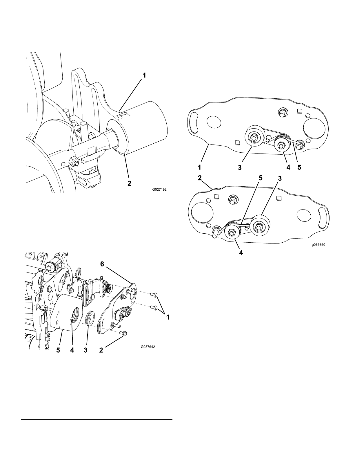
5.Loosenthe2bolts,washers,andnutssecuring
thedrive-bearinghousingtothebearing-housing
mountingbracket(Figure22).
6.Slidethehighheight-of-cutbrushontothebrush
shaft(Figure22).
7.Clampthebrushontotheshaftwiththe2J-bolts
andnutspreviouslyremoved(Figure22).
Important:Insertthethreadedendofthe
J-boltsthroughtheouterholesofthebrush
shaftwhilehookingthecurvedendsofthe
J-boltsintotheinnerholes.
8.TorquetheJ-boltlocknutsto2to3N∙m(20to
25in-lb).
g037645
Figure22
1.Highheight-of-cutbrush3.Loosenthesebolts.
2.J-bolts4.Nuts
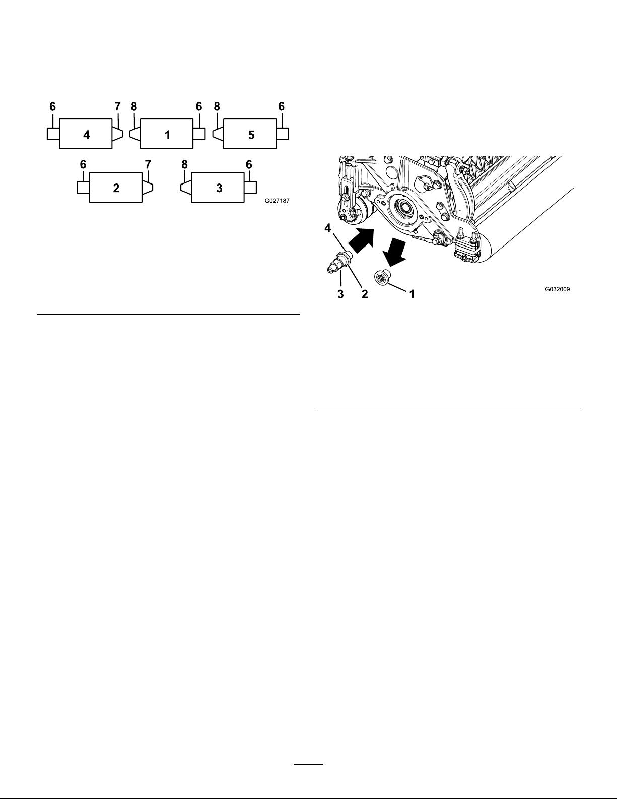
9.Installtheexcludersealandthenon-drive
bearinghousingontothebrushshaft(Figure21).
10.Mountthenon-drivebearinghousingtothe
bearing-housingmountingbracketwiththe2
bolts,washers,andnutspreviouslyremoved.
Note:Becarefulnottoknockthesealspring
off.
11.Tightenthe2bolts,washers,andnutssecuring
thedrive-bearinghousingtothebearing-housing
mountingbracket.
Maintenance
•Ensurethatthebrushisparalleltotherollerwith
1.5mm(0.060inch)clearancetolightcontact.
•Greasethettingsevery50hoursandafterevery
washing.
•Whenreplacingarollerbrush,torquetheJ-bolts
to2to3N∙m(20to25in-lb).
•Whenreplacingthebrush-shaft-drivenpulley,
torquethenutto36to45N∙m(27to33ft-lb).
•Whenreplacingthebrush-drivepulley,apply242
Loctite(blue)andtorquetheboltto47to54N∙m
(35to40ft-lb).
Note:Therollerbrush,theidlerbearing,andthebelt
areconsideredconsumableitems.
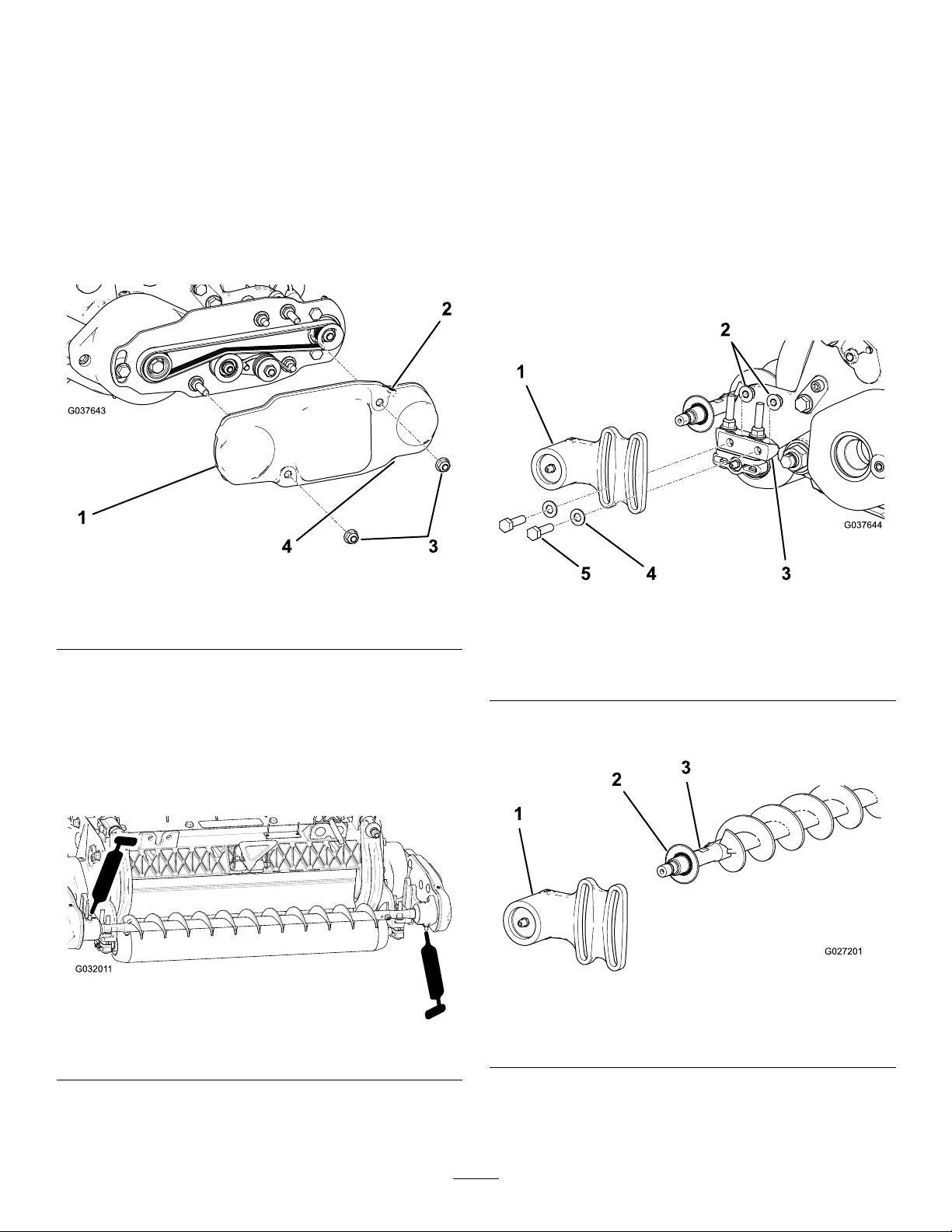
CheckingthePulley
Alignment
Important:Ensurethatthebeltisproperly
tensionedpriortocheckingthealignment.
1.Layastraightedgealongtheouterfaceofthe
drivepulley(Figure23).
Important:Onlylaythestraightedgeacross
thedrivepulley,donotlayitacrossthedrive
andthedrivenpulley.
2.Ensurethattheouterfacesofthedrivepulley
andthedrivenpulleyareinlinewithin0.76mm
(0.030inch).
Important:Donotusetheidlerpulleyto
checkthealignment.
3.Ifthepulleysarenotaligned,refertoAdjusting
thePulleyAlignment(page10).
Important:Thebeltmayfailprematurelyif
thepulleysarenotproperlyaligned.
g027197
Figure23
9

AdjustingthePulley
Alignment
1.Thedrivenpulley(attheroller-brushshaft)can
moveinorout(Figure24).
Note:Makenoteofwhichwaythepulleyneeds
tomovewhencheckingthebeltalignment;refer
toCheckingthePulleyAlignment(page9).
g037639
Figure24
1.Drivenpulley3.Driven-pulleynut
2.Idlerpulley
2.Whilerotatingthereel,whichrotatesthedrive
pulley,prythebeltoffthedrivepulley(Figure
24).
Note:Wearapaddedgloveoruseaheavyrag
torotatethereel.
3.Removethelocknutsecuringthedrivenpulley
tothebrushshaft(Figure24orFigure25).
Note:Usea1/2-inchwrenchontheroller-brush
shaftatstokeepitfromrotating.
4.Removethedrivenpulleyfromtheshaft(Figure
25).
5.Ifthepulleyneedstomoveout,adda0.8mm
(0.032inch)thickwasher(Figure25).
Important:Ifthepulleyneedstomovein,
removetheexisting0.8mm(0.032inch)thick
washer.
6.InstallthepulleyasshowninFigure25.
g009077
Figure25
1.Locknut3.Washer—0.8mm(0.032
inch)thick
2.Drivenpulley4.Brush-shaftats
7.Whileholdingtheatsoftheroller-brushshaft,
securethedrivenpulleyontheshaftwiththe
angenut(3/8–16)previouslyremoved.
Note:Seatthelocknut;thentorqueitto36to
45N∙m(27to33ft-lb).
8.Installthebeltontothepulleysasfollows:
A.Loopthebeltaroundthedrivepulleyand
thenoverthetopoftheidlerpulley(Figure
26).
g031875
Figure26
1.Drivenpulley3.Drivepulley
2.Idler-pulleyassembly4.Belt
B.Startthebeltonthedrivenpulley(Figure
26).
C.Usea9/16-inchdeep-wellsockettorotate
thebrushassemblyandguidethebeltonto
thedrivenpulley(Figure27).
10

g020390
Figure27
1.Belt2.9/16-inchdeep-wellsocket
Important:Ensurethattheribsonthebelt
areproperlyseatedinthegroovesineach
pulleyandthatthebeltisinthecenterofthe
idlerpulley.
9.Checkthepulleyalignment;refertoChecking
thePulleyAlignment(page9).
RestrainingtheReel
WARNING
Thecuttingreelbladesaresharpandcapable
ofamputatinghandsandfeet.
•Keepyourhandsandfeetoutsideofthe
reel.
•Ensurethatthereelisrestrainedbefore
servicingit.
RestrainingtheReelforRemoving
ThreadedInserts
1.Loosentheshield-boltontheleftsideofthe
cuttingunitandraisetherearshield(Figure28).
2.Insertalong-handledprybar(recommended
3/8"x12"withscrewdriverhandle)throughthe
backofthecuttingreel,closesttothesideofthe
cuttingunitthatyouwillbetorquing(Figure28).
3.Placetheprybaragainsttheweldsideofthe
reelsupportplate(Figure28).
Note:Inserttheprybarbetweenthetopofthe
reelshaftandthebacksof2reelbladessothat
thereelwillnotmove.
Important:Donotcontactthecuttingedge
ofanybladeswiththeprybar;thismay
damagethecuttingedgeand/orcauseahigh
blade.
Important:Theinsertontheleftsideof
thecuttingunithasleft-handthreads.The
insertontherightsideofthecuttingunithas
right-handthreads.
11

g280383
Figure28
1.Threadedinsertfor
removal
4.Reelshaft
2.Loosentheshieldbolt.5.Reelsupportplate
3.Rearshield6.Prybarinsertedalong
theweldsideofthereel
supportplate.
4.Restthehandleoftheprybaragainsttherear
roller.
5.Completetheremovalofthethreadedinsert
whileensuringthattheprybarstaysinplace,
thenremovetheprybar.
6.Lowertherearshieldandtightentheshield-bolt.
RestrainingtheReelforInstalling
ThreadedInserts
1.Insertalong-handledprybar(recommended
3/8"x12"withscrewdriverhandle)throughthe
frontofthecuttingreel,closesttothesideofthe
cuttingunitthatyouwillbetorquing(Figure29).
2.Placetheprybaragainsttheweldsideofthe
internalcuttingreelreinforcement(Figure29).
Note:Theprybarshouldcontactabladeatthe
front,thereelshaft,andabladeatthebackof
thebackofthereel,lockingitinplace.
Important:Donotcontactthecuttingedge
ofanybladeswiththeprybar;thismay
damagethecuttingedgeand/orcauseahigh
blade.
Important:Theinsertontheleftsideof
thecuttingunithasleft-handthreads.The
insertontherightsideofthecuttingunithas
right-handthreads.
g280384
Figure29
1.Threadedinsertfor
installation
3.Weldsideofsupportplate
2.Reelshaft4.Prybar
3.Restthehandleoftheprybaragainsttheroller
4.Pertheinsert’sinstallationinstructionsand
torquerequirements,completetheinstallationof
thethreadedinsertwhileensuringthatthepry
barstaysinplace,thenremovetheprybar.
12

Notes:

Notes:

Notes:

DeclarationofIncorporation
TheT oroCompany,8111LyndaleAve.South,Bloomington,MN,USAdeclaresthatthefollowingunit(s)
conform(s)tothedirectiveslisted,wheninstalledinaccordancewiththeaccompanyinginstructionsontocertain
ToromodelsasindicatedontherelevantDeclarationsofConformity.
ModelNo.SerialNo.ProductDescriptionInvoiceDescriptionGeneralDescriptionDirective
133-0157—
RearRollerBrushMVPKit,
Reelmaster5010-HSeries
CuttingUnitwith5inReel
RM5010/35505"X22"
RRBMVPKITRollerBrushKit2006/42/EC
133-0158—
RearRollerBrushMVPKit,
Reelmaster5010-HSeries
CuttingUnitwith7inReel
RM5010/35757"X22"
RRBMVPKITRollerBrushKit2006/42/EC
RelevanttechnicaldocumentationhasbeencompiledasrequiredperPartBofAnnexVIIof2006/42/EC.
Wewillundertaketotransmit,inresponsetorequestsbynationalauthorities,relevantinformationonthispartly
completedmachinery.Themethodoftransmissionshallbeelectronictransmittal.
ThismachineryshallnotbeputintoserviceuntilincorporatedintoapprovedT oromodelsasindicatedonthe
associatedDeclarationofConformityandinaccordancewithallinstructions,wherebyitcanbedeclaredin
conformitywithallrelevantDirectives.
Certied:AuthorizedRepresentative:
MarcelDutrieux
ManagerEuropeanProductIntegrity
ToroEuropeNV
Nijverheidsstraat5
2260Oevel
Belgium
JohnHeckel
Sr.EngineeringManager
8111LyndaleAve.South
Bloomington,MN55420,USA
February15,2019
This manual suits for next models
1
Table of contents
Other Toro Lawn Mower Accessories manuals

Toro
Toro RT1200 User manual

Toro
Toro 78534 User manual

Toro
Toro 114-1584 User manual

Toro
Toro 31950 User manual

Toro
Toro 99-8515 User manual

Toro
Toro Kevlar 02878 User manual

Toro
Toro 23163 User manual

Toro
Toro Groundsmaster 300 Series User manual

Toro
Toro Groundsmaster 200 Series User manual

Toro
Toro 30346 User manual