Toro GREENS AERATOR 09120 User manual

®
OPERATOR’S
MANUAL
FORM NO. 3318--399GB
MODEL NO. 09120—60001 & UP
GREENS AERATOR
©The Toro Company—1996
To assure maximum safety, optimum performance, and gain
knowledge of the product, it is essential that you or any other
operator read and understand the contents of this manual
before the engine is ever started. Pay particular attention to
the SAFETY INSTRUCTIONS highlighted by this symbol—
The safety alert symbol means CAUTION, WARN-
ING or DANGER—personal safety instruction.
Failure to comply with the instruction may result in
personal injury.

2
TABLE OF CONTENTS
Page
Safety Instructions 3
Safety and Instruction Decals 5
Before Operating 7
Check Crankcase Oil 7
Fill Fuel Tank with Gasoline 7
Check Hydraulic System Fluid 8
Controls 9
Operating Instructions 10
Starting/Stopping Engine 10
Install Tines 10
Adjust Coring Depth 11
Check Frame Height 11
Operating Procedure 12
Check Interlock System 12
Override System 13
Training Period 14
Before Aerating 14
Aerating Procedure 14
Transport Operation 14
Inspection and Cleanup After Use . 14
Lubrication 15
Troubleshooting 17
Foreword
The Greens Aerator has advanced concepts in engineering, design and safety; and if maintained properly, will give excel-
lent service.
Since this is a high-quality product, Toro is concerned about the future use of the machine and safety of the user.
Therefore, read this manual to familiarize yourself with proper set-up, operation and maintenance instructions. The
major sections of the manual are:
1. Safety Instructions 3. Operation
2. Before Operating 4. Lubrication
Certain information in this manual is emphasized. DANGER, WARNING and CAUTION identify personal safety relat-
ed information. IMPORTANT identifies mechanical information demanding special attention. Be sure to read this
directive because it deals with the possibility of damaging a part or parts of the machine. NOTE identifies general infor-
mation worthy of special attention.

This safety alert symbol means CAUTION, WARNING or
DANGER — “personal safety instruction.” Read and
understand the instruction because it has to do with safety.
Failure to comply with the instruction may result in per-
sonal injury.
Improper use or maintenance of the machine can result in
injury. To reduce the potential for injury, comply with the
following safety instructions.
BEFORE OPERATING
1. Read and understand the contents of this Operator’s
Manual before operating the machine. Become
familiar with all controls and know how to stop
quickly. A free replacement manual is available by
sending complete Model and Serial Number to:
The Toro Company
8111 Lyndale Avenue South Minneapolis,
Minnesota 55420
2. Do not allow children to operate the machine. Do
not allow adults to operate the machine without prop-
er instruction.
3. Before attempting to start engine, disengage the trac-
tion drive and move the gear shift to neutral.
4. Remove all debris or other objects that might inter-
fere with operation. Keep all bystanders away from
the work area.
5. Keep all shields and safety devices in place. If a
shield, safety device or decal is defective or damaged,
repair or replace it before resuming operation. Also,
tighten any loose nuts, bolts and screws to assure the
machine is in safe operating condition.
6. Do not operate the machine while wearing sandals,
tennis shoes, sneakers or shorts. Also, do not wear
loose fitting clothing that could get caught in moving
parts. Always wear long pants and substantial shoes.
Wearing safety glasses, safety shoes, ear protection
and a helmet is advisable and required by some local
ordinances and insurance regulations.
7. Fill the fuel tank with gasoline before starting the
engine. Avoid spilling gasoline. Since gasoline is
flammable, handle it carefully.
A. Use an approved gasoline container.
B. Do not fill the tank while the engine is hot or
running,
C. Do not smoke while handling gasoline.
D. Fill the fuel tank outdoors and up to about one
inch (25 mm) from top of the tank, not the filler
neck.
E. Wipe up any spilled gasoline.
WHILE OPERATING
8. Start the engine when the traction drive is disen-
gaged, and the gear shift lever is in neutral.
9. Do not run the engine in a confined area without ade-
quate ventilation. Exhaust fumes are hazardous and
could possibly be deadly.
10. Using the machine demands attention, and to prevent
loss of control:
A. Use only in daylight or when there is good arti-
ficial light.
B. Watch for holes or other hidden hazards.
C. Do not transport the machine close to a sand
trap, ditch, creek or other hazard.
11. If the tines strike a solid object or the machine
vibrates abnormally, shut the engine off. Remove the
high-tension wire from the spark plug to prevent pos-
sibility of accidental starting, Check the coring head
and traction unit for damage and defective parts.
Repair any damage before restarting the engine and
operating the tines. Be sure the tines are in good
condition and all bolts are tight.
12. Do not touch the engine or muffler while the engine
is running or soon after it is stopped. These areas
could be hot enough to cause a burn.
13. Before leaving the operator’s position—behind han-
dle or leaving machine unattended, raise the coring
head, raise the lockup brackets, disengage the traction
drive, move the gear shift to neutral and shut OFF the
engine.
Safety Instructions
3

Safety Instructions
4
MAINTENANCE
14. Disconnect the high-tension wire from the spark plug
to prevent accidental starting of the engine when ser-
vicing, adjusting or storing the machine.
15. If the traction unit must be tipped to perform mainte-
nance or an adjustment, drain the gasoline from fuel
tank and oil from crankcase.
16. To reduce potential fire hazard, keep the engine free
of excessive grease, grass, leaves and accumulations
of dirt.
17. Be sure the machine is in safe operating condition by
keeping nuts, bolts and screws tight. Check the tine
mounting bolts and nuts frequently to be sure they are
tightened to specification.
18. If the engine must be running to perform a mainte-
nance adjustment, keep hands, feet, clothing and
other parts of the body away from the tines and other
moving parts.
19. Make sure all hydraulic line connectors are tight, and
all hydraulic hoses and lines are in good condition
before applying pressure to the system.
20. Keep body and hands away from pin hole leaks or
nozzles that eject hydraulic fluid under high pressure.
Use paper or cardboard, not hands, to search for
leaks. Hydraulic fluid escaping under pressure can
have sufficient force to penetrate skin and do serious
damage. If fluid is ejected into the skin it must be
surgically removed within a few hours by a doctor
familiar with this form of injury or gangrene may
result.
21. Before disconnecting or performing any work on the
hydraulic system, all pressure in system must be
relieved by stopping the engine and lowering the
implement to the ground.
22. Do not overspeed the engine by changing governor
settings. To be sure of safety and accuracy, have an
Authorized TORO Distributor check maximum
engine speed with a tachometer.
23. The engine must be shut off before checking oil or
adding oil to the crankcase.
24. Allow the engine to cool before storing the machine
in any enclosure such as a garage or storage shed.
Make sure the fuel tank is empty if the machine is to
be stored more than 30 days. Do not store the
machine near any open flame or where gasoline
fumes may be ignited by a spark. Always store gaso-
line in a safety approved, red metal container.
25. Perform only those maintenance instructions
described in this manual. If major repairs are ever
needed or assistance is desired, contact an Authorized
Toro Distributor. To ensure optimum performance
and safety, always purchase genuine TORO replace-
ment parts and accessories to keep the Toro all
TORO. NEVER USE “WILL-FIT”’ REPLACE-
MENT PARTS AND ACCESSORIES MADE BY
OTHER MANUFACTURERS. Look for the TORO
Iogo to assure genuineness. Using unproved replace-
ment parts and accessories could void the warranty of
The Toro Company
Sound &Vibration Levels
Sound Levels
This unit has an equivalent continuous A-weighted sound
pressure at the operator ear of: 92 dB(A), based on mea-
surements of identical machines per 84/538/EEC.
This unit has a sound power level of 104 dB(A)/1pW,
based on measurements of identical machines per proce-
dures outlined in Directive 79/113/EEC and amendments.
Vibration Level
This unit has a vibration level of 8.0 m/s2at the posterior,
based on measurements of identical machines per ISO
2631 procedures.

5
Symbol Glossary
SAFETY ALERT
SYMBOL GENERAL HAZARD
SAFETY ALERT CRUSHING OF
WHOLE BODY,
APPLIED FROM
ABOVE
CRUSHING OF
FINGERS OR HAND,
FORCE APPLIED
FROM SIDE
CUTTING OF
FINGERS OR HAND CUTTING OF FOOT CRUSHING OR
PUNCTURE OF FOOT,
CORING HEAD
WHOLE BODY ENTANGLEMENT,
IMPLEMENT INPUT DRIVE LINE FINGERS OR HAND
ENTANGLEMENT,
CHAIN DRIVE
THROWN OR FLYING
OBJECTS, WHOLE
BODY EXPOSURE
RUNOVER/BACKOVER,
GREENS AERATOR RUNOVER/BACKOVER,
HC 4000 AERATOR SECURE LIFTING CYLINDER WITH
LOCKING DEVICE BEFORE
GETTING IN HAZARDOUS AREA
INSERT SAFETY LOCK
BEFORE GETTING IN
HAZARDOUS AREA
STAY A SAFE DISTANCE FROM MACHINE,
GREENS AERATOR STAY A SAFE DISTANCE FROM MACHINE,
HC 4000 AERATOR
STAY CLEAR OF ARTICULATION
AREA WHILE ENFINE IS RUNNING,
GREENS AERATOR
DO NOT OPEN OR REMOVE
SAFETY SHIELDS WHILE
ENGINE IS RUNNING
SHUT OFF ENGINE & REMOVE
KEY BEFORE LEAVING OPERATOR
POSITION, GREENS AERATOR
CONSULT TECHNICAL MANUAL
FOR PROPER SERVICE
PROCEDURES
READ OPERATOR’S
MANUAL HEARING PROTECTION
MUST BE WORN BRAKE SYSTEM ENGAGE DISENGAGE

Symbol Glossary
6
P
1 INCH (25mm)
P
ON/START OFF/STOP FAST SLOW CONTINUOUS
VARIABLE,
LINEAR
ENGINE START ENGINE STOP
PARK UNLEADED FUEL FUEL TANK FILL
LINE LOCK UNLOCK CORING HEAD
ALWAYS HAVE CORING HEAD
FULLY UP FOR TRANSPORT &
FULLY DOWN FOR CORING
TRACTION DRIVE MANUAL CHOCK WHEELS IN PARKED POSITION,
ALWAYS PARK ON LEVEL SURFACE,
FAIRWAY AERATOR
ALWAYS FORK FROM FRONT OR REAR
OF MACHINE, HC 4000 AERATOR LEVER OPERATION

Engine: Briggs & Stratton, Vanguard, 4-cycle, air-cooled,
2-cylinder 11.9 kW (16 hp) @ 3600 rpm, 74.4 cm3(29.3
cu. in) displacement. Electric start. Large capacity dual
element air cleaner. Full pressure lubrication 1.55 l (3.5
pint) oil capacity. Solid-state electronic ignition.
Electrical: 12-volt battery, 32-amp-hour. 16-amp alterna-
tor. Ignition switch and interlock switches on control han-
dle, transmission and coring head clutch.
Fuel Capacity: 17 l (4.5 gallons) unleaded gasoline.
Traction Drive: Double-banded V-belt from mechanical
clutch on engine to Peerless Model 2361 transaxle. Two
speeds forward and one reverse. Wheels driven individual-
ly by chains from transaxle.
Ground Speed:
1st Gear Forward: 1.8 km/h @ 3600 rpm (coring)
2nd Gear Forward: 5.3 mph @3600 rpm (transport)
Reverse: 3.1 km/h @ 1800 rpm.
Ground Clearance: 10.2 cm (4 inches).
Tires/Wheels: Two steering tires (front): 13 X 5.00-6, 2
ply, rib tread tubeless.
Two drive tires (rear): 18 X 9.50-8, 4 ply, Rib Terra
tubeless. Drop center demountable rims, greaseable
tapered roller bearings.
Recommended tire pressure for front and back tires is 69
kPa (10 psi).
Frame: Welded steel construction—tricycle.
Service Brake: Disc-type mounted to transaxle.
Controls: Traction clutch, coring head hydraulic lift and
key switch on control console. Throttle and choke on
engine. Transaxle shift lever on frame. Interlock switches
and service brake on steering handle.
Implement Drive: Triple banded V-belt from engine to
coring head.
Coring Unit Construction: Welded steel frame con-
struction with four crankshafts mounted in precision ball
bearings. Crankshafts drive four coring arms/tine heads.
Drive: No. 50 O-ring sealed roller chain from counter-
shaft to coring crankshafts.
Lift: Single hydraulic cylinder powered by a vane type
pump. Control valve actuated by lift control lever.
Tine Heads: 4 individual heads each holding three tines.
Deflector chutes direct cores rearward away from drive
components.
Coring Width: 27 inches
Hole Pattern: 2.25 inches X 2.5 inches
Coring Depth: Up to 3.5 inches.
Tines: Case hardened tubing, hollow tapered design. 5/8"
tines standard. 12 tines required per unit.
Dimensions:
Length: 193 cm (76 inches)
Width: 141 (55.5 inches)
Height: 99.1 cm (39 inches)
Wheelbase: 111.8 cm (44 inches)
Weight: 461.8 kg (1236 pounds)
Optional Accessories:
5/8" Tine Part No. 59-3670
1/2" Tine Part No. 94-3419
3/8" Tine Part No. 59-3690
3/8" Slotted Tine Part No. 94-3418
5/8" Long Wear Tine Part No. 59-9770
5/16" Solid Spiker Tine Part No. 77-5320
*3/4" Tine Part No. 62-4600
*3/4" Slotted Tine Part No. 92–7941
*Tine Block Part No. 62-4610
3/8" Slotted Tine Kit Part No. 94-6814
1/4" Spiker Tine Kit Model 09153
Windrower Model 09150
Coring Head Stand Model 09152
Tire Scrapers Model 09151
*3/4" tines requires 8 optional Tine blocks
7
Specifications

8
ACTIVATE AND CHARGETHE
BATTERY
1. Since the battery is not filled with electrolyte or acti-
vated, bulk electrolyte with 1.260 specific gravity
must be purchased from a local battery supply outlet.
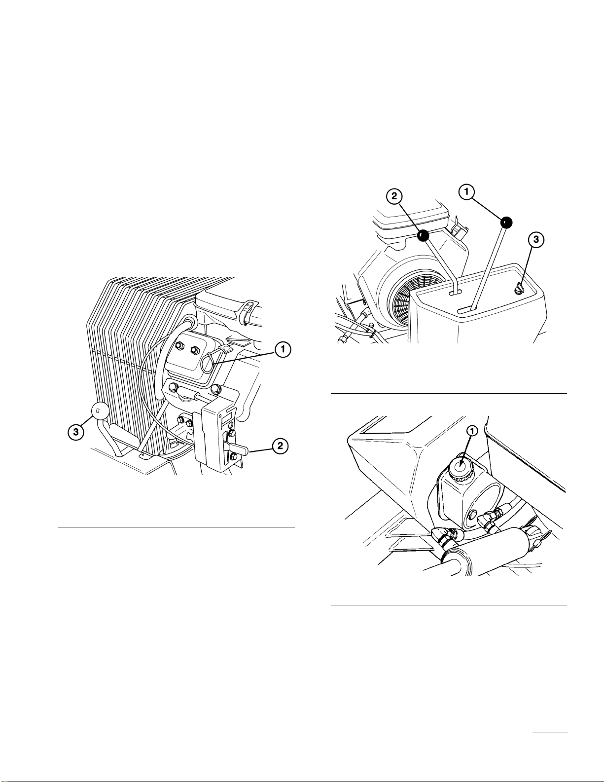
2. Remove the wing nuts and washers securing the bat-
tery clamp to the battery bolts and remove the battery
from the machine. Remove the filler caps from the
battery and slowly fill each cell until electrolyte is
just above the plates (Fig. 1)
Figure 1
1. Wing nuts & washers 3. Battery pad
2. Battery clamp 4. Support rods
3. Replace filler caps and connect a 3- to 4-am battery
charger to the battery posts. Charge the battery at a
rate of 3 to 4 amperes for 4 to 8 hours.
4. When the battery is charged, disconnect the charger
from the electrical outlet and battery posts.
5. Remove the filler caps. Slowly add electrolyte to each
cell until the level is up to the fill ring. Install the
filler caps.
Important: Do not over-fill the battery. Electrolyte
will overflow onto other parts of the machine and
sever corrosion and deterioration will result.
6. Mount the battery on the battery pad with the termi-
nal posts toward the rear of the machine.
7. Secure the battery with the battery bolts, clam, wash-
ers and wing nuts (Fig 2).
8. Install the positive cable (rubber boot over the end) to
the positive terminal and the negative cable (black to
the negative terminal of the battery and secure with
carriage bolts, lockwashers and nuts. Slide the rubber
boot over the positive terminal to prevent possible
short-out.
CHECKTHE CRANKCASE OIL
The engine is shipped with 1.5 l of oil in the crankcase;
however, the oil level must be checked before and after the
engine is first started.
1. Position the machine on a level surface.
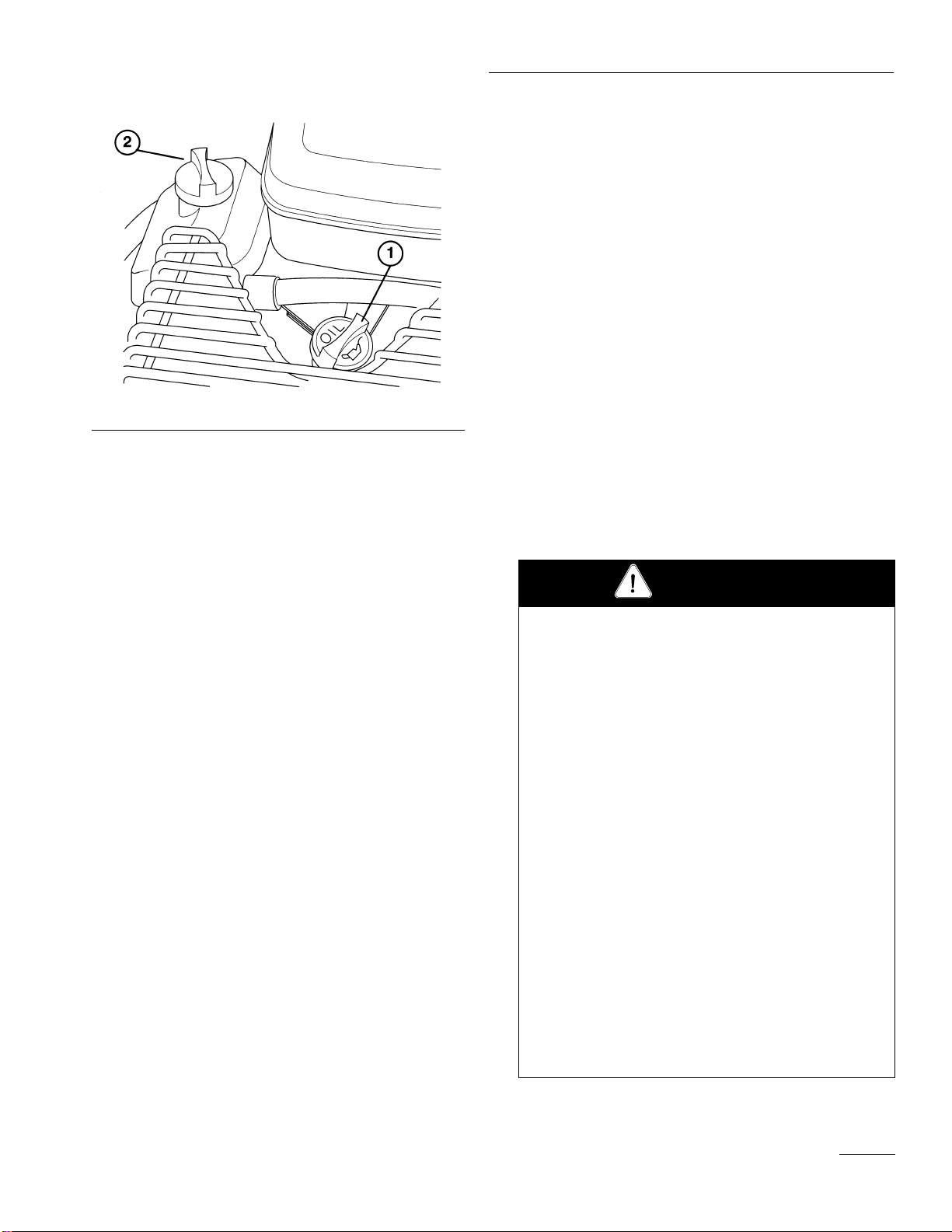
2. Remove the dipstick and wipe it with a clean rag.
Push the dipstick down into the dipstick tube and
make sure it is seated fully. Pull the dipstick out and
check the level of oil (Fig. 2). If the oil level is low,
add enough oil to raise the level to the FULL mark
on dipstick.
Before Operating
Wear safety goggles and rubber gloves when work-
ing with electrolyte. Charge the battery in a well-
ventilated place so gases produced while charging
can dissipate. Since the gases are explosive, keep
open flames and electrical spark away from the bat-
tery; do not smoke.
Nausea may result if the gases are inhaled. Unplug
the charger from the electrical outlet before connect-
ing or disconnecting charger leads.
CAUTION
Before Operating
9
Figure 2
1. Dip stick 2. Filler cap
3. Remove the filler cap and pour oil into the filler neck
until the level is at the FULL mark on the dipstick.
The engine uses any high-quality oil having the
American Petroleum Institute—API- “service classifi-
cation” SF. Oil viscosity—weight —must be selected
according to ambient temperature. Temperature/ vis-
cosity recommendations are:
A. Above +32°F (0° C)—Use SAE 30, and if it is
not available, 10W-30 or 10W-40 are acceptable
substitutes.
B. Below +32°F (0° C)—Use SAE 5W-20 or 5W-
30, and if they are not available. 10W30 or
10W-40 are acceptable substitutes.
IMPORTANT: Check the oil level every eight (8)
operating hours or daily. Initially, change the oil
after the first 8 hours of operation; thereafter,
under normal conditions, change the oil after each
50 hours of operation and the filter after every 100
hours of operation. However, change the oil more
frequently when the engine is operated in extreme-
ly dusty or dirty conditions, under heavy load or
in high ambient temperatures.
FILLTHE FUELTANK WITH
GASOLINE
This engine is certified to operate on unleaded gasoline.
Use clean, fresh, unleaded gasoline with a minimum of 85
octane. Do not mix oil with gasoline. Purchase fuel in
quantity that can be used within 30 days to assure fuel
freshness. Use Briggs & Stratton Gasoline Additive (See
your authorized Briggs & Stratton Service Dealer for Part
No. 5041 or the single-use pouch.)
In countries other than the U.S.A., leaded gasoline may
be used if it is commercially available and unleaded is
unavailable.
Note: Some fuels called oxygenated or reformulated
gasolines, are gasoline blended with alcohols or ethers.
Excessive amounts of these blends can damage the fuel
system or cause performance problems. Do not use
gasoline which contains Methanol. If any undesirable
operating symptoms occur, use gasoline with a lower
percentage of alcohol or ether.
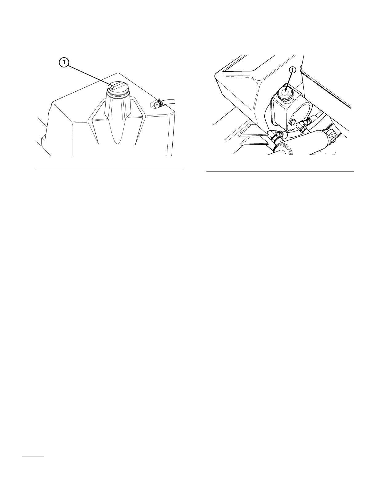
1. Remove the cap from the fuel tank (Fig. 2) and fill
the 4.5 gallon tank to within 1 inch from the top with
unleaded gasoline. Install the fuel tank cap tightly.
Because gasoline is flammable, use caution when
storing or handling it. Do not fill the fuel tank
while the engine is running, hot or when the
machine is in an enclosed area. Vapors may build
up and be ignited by a spark or flame source many
feet away. DO NOT SMOKE while filling the fuel
tank to prevent the possibility of an explosion.
Always fill the fuel tank outside and wipe up any
spilled gasoline before starting the engine. Use a
funnel or spout to prevent spilling gasoline before
starting the engine and fill the tank to about 1 inch
(25 mm) below the filler neck. Store gasoline in a
clean safety-approved container and keep the cap in
place on the container. Keep gasoline in a cool,
well-ventilated place; never in an enclosed area such
as a hot storage shed. To assure volatility, do not
buy more than a 30-day supply of gasoline.
Gasoline is a fuel for internal combustion engines;
therefore, do not use it for any other purpose. Since
many children like the smell of gas, keep it out of
their reach because the fumes are explosive and dan-
gerous to inhale.
DANGER
10
Figure 3
1. Vented fuel tank cap
2. To prevent a fire hazard, wipe up gasoline that may
have spilled.
CHECK HYDRAULIC SYSTEM
FLUID
The hydraulic system is designed to operate on SAE 10
W-30 engine oil or, as a substitute, SAE 10 W-40 engine
oil. The machine’s reservoir is filled at the factory with
2.7 pints of SAE 10 W-30 engine oil. However, check the
level of hydraulic fluid before the engine is first started
and daily thereafter.
1. Position the machine on a level surface and raise the
coring head to the full up position.
2. Remove the dipstick cap (Fig. 4) from the filler neck
and wipe it with a clean cloth. Insert the dipstick cap
into the filler neck; then remove it and check the level
of fluid. If the level is not within 1.25 cm (1⁄2inch)
from the full mark on the dipstick, add SAE 10W-30
engine oil to raise the level to full mark. Do not
overfill.
3. Install the dipstick filler cap onto the filler neck.
4. Run the engine for one minute, recheck the level of
fluid and add oil as needed.
Figure 4
1. Dip stick cap
11
Ignition Switch (Fig. 5)—The ignition switch, which is
used to start and stop the engine, has three positions: OFF,
ON and START. Rotate key clockwise—START posi-
tion—to engage starter motor. Release key when the
engine starts. The key will automatically return to the ON
position. To shut the engine off, rotate key counter-
clock–wise to the OFF position.
Choke (Fig. 5)—To start a cold engine, close the carbure-
tor choke by pulling the choke control outward to the ON
position. After the engine starts, regulate the choke to
keep the engine running smoothly. As soon as possible,
open the choke by pushing it inward to the OFF position.
A warm engine requires little or no choking.
Figure 5
1. Choke
2. Throttle
3. Gear shift lever
Throttle (Fig. 5)—The throttle is used to operate the
engine at various speeds. Moving the throttle upward
increases engine speed—FAST; rearward decreases engine
speed—SLOW. The throttle controls the speed of the cor-
ing head and, in conjunction with traction clutch, controls
the ground speed of the machine.
Gear Shift Lever (Fig. 5)—The transmission has two for-
ward speeds, neutral and reverse, and has an inline shaft
pattern. Do not shift while unit is moving, because trans-
mission damage may occur.
Traction Drive Lever (Fig.6)—Shift to the desired gear
and move the traction drive lever to the engage position to
move forward or reverse. One of the hand-operated inter-
lock levers (Fig. 7).
Coring Head Lever (Fig. 6)—Raises and lowers the cor-
ing head and engages and disengages the drive.
Figure 6
1. Traction drive lever
2. Coring head lever
3. Ignition switch
Figure 7
1. Interlock lever switches 2. Service brake
Interlock Lever Switches (2) (Fig. 7)—Switches permit
engine operation when the coring head is lowered. They
also hold the traction drive lever in the engaged position.
One handle switch must be activated before engaging the
traction drive or lowering the coring head when engine is
running.
C
on
t
ro
l
s

12
Operating
Service Brake (Fig. 7)—Used to slow the traction opera-
tion.
STARTING/STOPPING ENGINE
1. Make sure both wires are installed on the spark plugs.
2. Make sure the traction drive is disengaged and the
gear shift lever is in Neutral.
3. Pull the choke lever out to the ON position—when
starting a cold engine—and the throttle lever to the
mid position.
4. Insert the key into the ignition switch and turn it
clockwise to start the engine. Release the key when
the engine starts. Gradually return the choke lever to
the OFF position (lever all the way in) after the
engine starts and warms up.
IMPORTANT: To prevent overheating of the
starter motor, do not the starter longer than 10 sec-
onds. After 10 seconds of continuous cranking,
wait 60 seconds before engaging the starter again.
5. Make sure the coring head is in the raised position.
Note: When starting the engine for the first time, or
after engine, transmission or axle overhaul, operate
the machine in forward and reverse for one to two
minutes to be sure all parts operate correctly.
6. To stop the engine, move the throttle control down-
ward to the SLOW position and turn the ignition key
to “OFF”,
INSTALLTHE TINES
1. Start the engine: refer to Starting/Stopping instruc-
tions.
2. Move the coring head lever to the “UP” position to
raise the coring head.
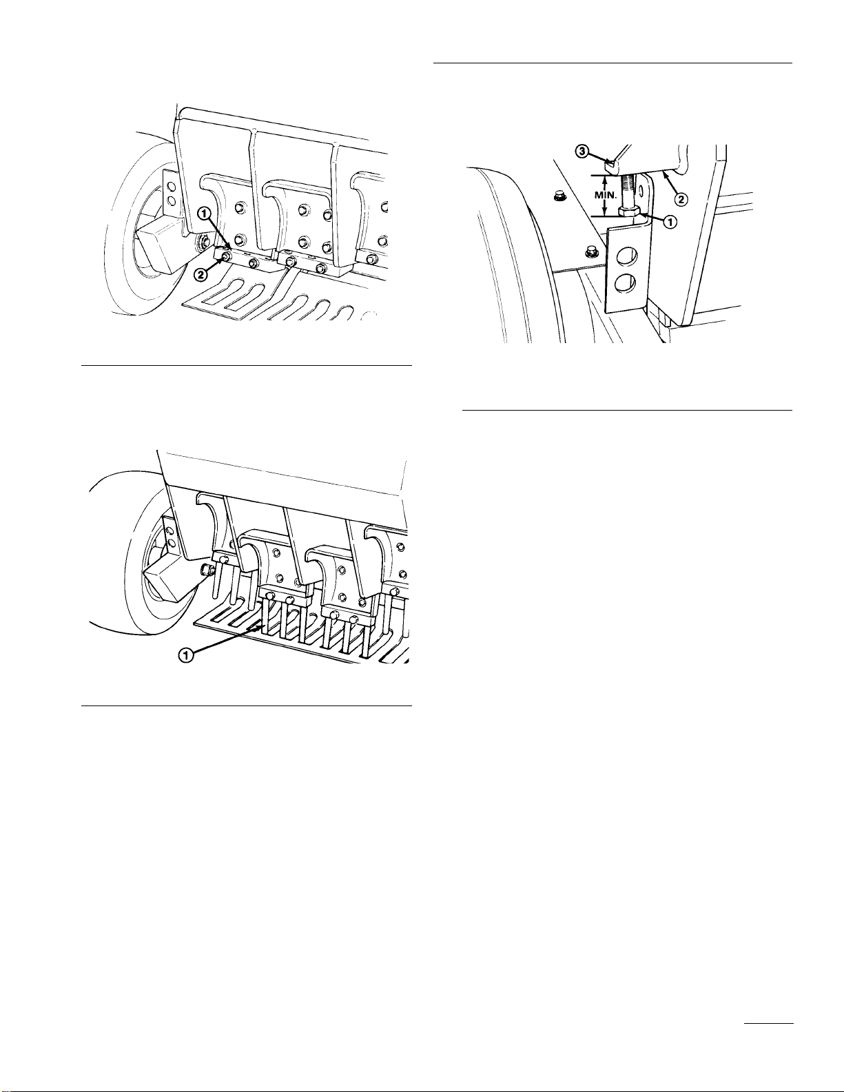
3. Stop the engine and raise the lock-up brackets on
each side of the chassis (Fig. 8). Lower the coring
head until it rests on brackets.
Figure 8
1. Lock-up bracket
4. Loosen (2) hex nuts on each tine block until tines can
be inserted. Insert tines until they bottom out on the
flange in the tine block (Fig. 8).
Operating Instructions
Operating
13
Figure 9
1. Tine block
2. Mounting nut
5. Tighten the mounting nuts to 100-110 ft/lb. torque
(Fig. 10).
Figure 10
1. Tine
ADJUSTTHE CORING DEPTH
1. Raise the coring head and engage the lock-up brack-
ets.
2. Loosen the jam nut on top of the adjusting bracket
(Fig. 11).
3. Thread the adjusting screw into the bracket to
increase coring depth. Thread it out to decrease
depth (Fig.11).
4. Repeat this procedure using the long end of the
height gauge on each rear wheel spindle (Fig. 13).
Figure 11
1. Coring depth adjustment screw
2. Adjusting bracket
3. Jam nut
5. Best recommended coring depth is achieved when the
distance from the end of the screw head to the brack-
et is 11⁄16” (Fig. 11).
IMPORTANT: Do not adjust the screw to a setting
less than 11⁄16” or damage to turf guards may
occur.
6. Make sure adjustments are the same on both sides of
the coring head and tighten the jam nuts.
CHECK FRAME HEIGHT
1. Position the machine on a level surface.
2. Slide the short end of the frame height gauge under
the front axle to verify height. The gauge should
contact the axle when on the floor. Check both sides
(Fig. 12).

14
Operating
Figure 12
1. Front axle 2. Height gauge
3. Increase or decrease tire pressures to attain the
required height.
4. Repeat the procedure using the long end of the height
gauge on each rear wheel spindle (Fig. 13).
5. Regulate tire pressure as required.
Figure 13
1. Rear wheel spindle
2. Height gauge Regulate tire pressure as required.
OPERATING PROCEDURE
1. Make sure wire is installed on spark plug and fuel
valve is open.
2. Start the engine: refer to Starting/Stopping instruc-
tions.
3. Make sure coring head is in the up position.
4. Squeeze left interlock lever against handle.
5. Move shift lever to “L” (low) for Coring or “H”
(high) for Transport.
Note: If you encounter resistance during gear selec-
tion, jog the clutch handle until the gears align. Do
not shift gears while machine is moving. DO NOT
FORCE SHIFT LEVER AS DAMAGE WILL
OCCUR.
6. Move traction drive lever to engage position.
7. To engage and lower coring head, move coring head
lever to down position and hold until coring head is
completely lowered.
CHECK INTERLOCK SYSTEM
The safety interlock system’s purpose is to prevent the
engine from cranking or starting unless the traction drive
lever is disengaged and the coring head is raised. It also
interrupts engine operation if a handle-mounted interlock
lever is not activated when the coring head is lowered.
To check the interlock system:
1. Position the machine on a flat, open area. Start the
engine; refer to Starting and Stopping instructions.
2. Check the clutch switch (Fig. 14) with a continuity
tester or ohm meter and replace it if damaged. The
switch must be closed when the gear shift lever is in
a gear. The switch must open when shifting between
Neutral, First, and Second gears.
3. To adjust the switch, loosen the mounting screws and
reposition the switch as required.
4. If the coring head is in the raised position and the
engine will not start, or continues to run when the
coring head is down and the interlock lever(s)
released, there is a defect in the interlock system, pro-
ceed to step 5.
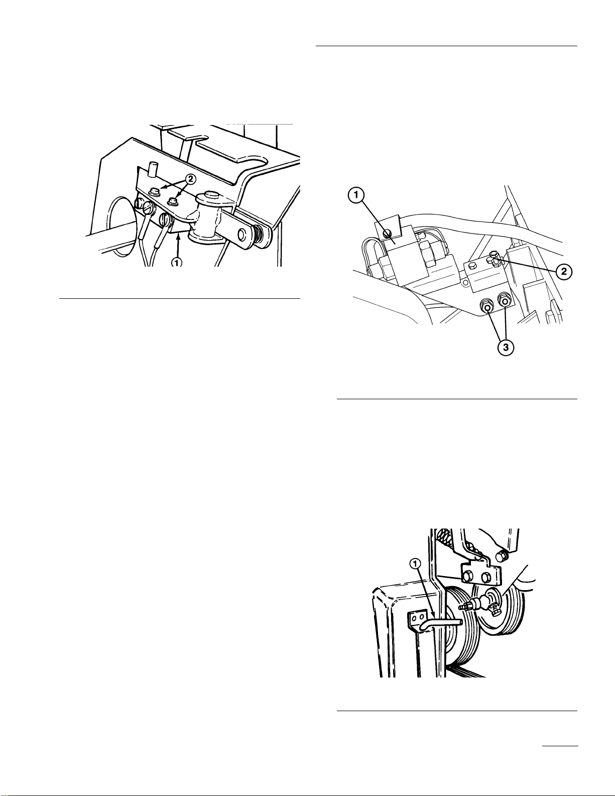
5. Check the coring head switch (Fig. 15) with a conti-
nuity tester or ohm meter and replace if damaged.
The switch plunger must be depressed when the cor-
ing head is in the raised position.
Operating
15
Note: Before coring head switch can be adjusted,
coring head drive belt must be correctly adjusted..
Figure 14
1. Traction switch
2. Mounting screws
6. If an adjustment to the switch is required, proceed as
follows:
A. Stop the engine and lower the coring head onto
the stand.
B. Remove the override pin from the storage brack-
et on the front of the coring head cover
(Fig. 16).
C. Push down on the override lever (Fig. 14) until
the holes in lever bracket and the coring bracket
are aligned, then insert the pin through the
holes.
D. Loosen the adjusting screw jam nut and (2)
flange nuts (Fig. 12).
E. Turn the ignition switch to the START position,
but do not start the engine.
F. While holding the ignition switch in the START
position, tighten the adjusting screw until the
engine cranks.
G. Release the ignition switch and tighten the
adjusting screw one more turn.
H. Tighten the adjusting screw jam nut and (2)
flange nuts.
I. Restart the engine and raise the coring head.
J. Stop the engine, remove the override pin and
reinstall it in the storage bracket.
K. Start the engine and check all modes of opera-
tion. The coring head should not run when on
coring head lock-up brackets.
Figure 15
1. Coring head switches
2. Adjusting screw & jam nut
3. Mounting screws
OVERRIDE SYSTEM
The coring head is equipped with a release mechanism
that allows the engine to be started when the coring head
is in the lowered position.
1. Remove override pin from storage bracket on front of
coring head cover (Fig. 16).
Figure 16
1. Override pin

16
Operating
2. Push down on override lever until holes in lever
bracket and coring head are aligned, then insert pin
through holes (Fig. 17).
Figure 17
1. Override lever
2. Lever bracket
3. Override pin
3. Restart the engine and raise the coring head.
4. Stop the engine, remove the pin and reinstall in stor-
age bracket.
TRAINING PERIOD
Before aerating greens with the Greens Aerator, find a
clear area and practice starting and stopping, raising and
lowering coring head, turning, etc. This training period
will help the operator gain confidence in the performance
of the Greens Aerator.
BEFORE AERATING
Inspect the green for debris and determine the best direc-
tion and pattern to operate machine.
AERATING PROCEDURES
1. Approach the green with the gear shift lever in the
“L” (low) position.
2. Lower the coring head after you attain the desired
starting position. Make sure the coring head is
engaged before the tines are within one inch of the
turf.
3. Use the rubber guides hanging from front of chassis
to align rows.
TRANSPORT OPERATION
Make sure the coring head is in the up position and the
coring head lock-up brackets are up. Set the gear shift
lever in the “H” (high) position if faster ground speed is
required. Use the service brake to slow the machine while
going down steep hills to avoid loss of control. Always
approach rough areas at a reduced speed and cross severe
undulations carefully.
INSPECTION AND CLEAN-UP
AFTER USE
At completing operation, thoroughly wash the machine
with a garden hose without a nozzle so excessive water
pressure will not cause contamination and damage the
seals and bearings. After cleaning, inspect the machine
for possible hydraulic fluid leaks, damage or wear to
hydraulic and mechanical components and check the tines
for sharpness.
Always have the coring head fully raised when
transporting and fully lowered when coring so the
safety interlock system functions correctly. If the
coring head lowers by itself, correct this malfunc-
tion before continuing operation.
CAUTION

Lubrication
The Greens Aerator has grease fittings that must be lubri-
cated daily with No. 2 General Purpose Lithium Base
Grease. Damper pivots must be lubricated every 4 hours
of operation.
The bearings and bushings that must be lubricated are:
front wheels (Fig. 18), rear wheel spindles (Fig. 19), front
handle shaft (Fig. 20), damper pivots (4) (Fig. 21), traction
roller latch pin (Fig. 22) speed control lever (Fig 23) and
coring head switch (Fig. 24).
Figure 18
Figure 19
Figure 20
Figure 21
Figure 22
Figure 23
Figure 24
17
Maintenance

18
Maintenance
✓Safety interlock operation
✓Brake operation
✓Fuel level
✓Engine oil
✓Frame height
✓Air Filter/pre-cleaner condition
✓Clean the engine cooling fins
✓Hydraulic system oil level
✓Unusual operating noises
✓Tine & stomper arm condition
✓Hydraulic hoses for damage
✓Fluid leaks
✓Tire pressure
✓Instrument operations
✓Tighten loose fasteners
✓Lubricate dampener pivots1
✓Lubricate all grease fittings1
✓Touch-up damaged paint
1 = Immediately after every washing, regardless of the
interval listed
Maintenance Procedure Maintenance Interval & Service
✝Initial break in at 8 hours
Change the engine oil filter
Service the spark plugs
Grease the wheel bearing
Grease the steering handle spindle
Check the battery fluid level
Check the battery cable connections
Check the coring head chain tension
Check the hydraulic pump belt tension
Replace safety switches
Change transaxle gear lubricant
Replace the hydraulic oil
Adjust the valves and torque the head bolts
Decarbon the combustion chamber
✝Change the engine oil
Service the air filter cartridge
Lubricate the coring head switch assembly
Service the Air Filter Pre-Cleaner
Lubricate the Dampener Pivots
Check the condition of the tines
Check the engine oil level
Every
50 hours Every
100 hours
Every
25 hours
Every
5hours
Minimum Recommended Maintenance Intervals
Annual Recommendations:
Items are recommended every 500 hours or
one year, whichever occurs first.
Check Daily:
Maintenance
19
ENGINE CARE
The Engine Manual supplied with your Greens Aerator
provides the maintenance procedures for service of the air
cleaner, oil requirements, ignition components, etc.
Note: If the Greens Aerator is to be operated at altitudes
of 3000 feet or above sea level, it may require a high alti-
tude carburetor main jet. Order Part No. 8055537 from
your Authorized Briggs & Stratton Service Dealer.
CHANGING HYDRAULIC SYSTEM
OIL
The hydraulic system oil must be changed immediately
when any contamination, sludge, water or condensation
appears.
1. Remove the tines from the tine blocks and lower the
coring head; refer to Install Tines.
2. Position a drain pan under the chassis below the
pump assembly (Fig. 25).
3. Remove the hose clamp securing the return hose to
the pump. Disconnect the hose from the pump, allow-
ing oil to flow into the drain pan.
4. Connect the return hose to the pump and secure it
with the hose clamp.
Figure 25
1. Pump reservoir
5. Fill pump reservoir; refer to Checking Hydraulic
System Fluid.
6. Check all connections for possible leaks.
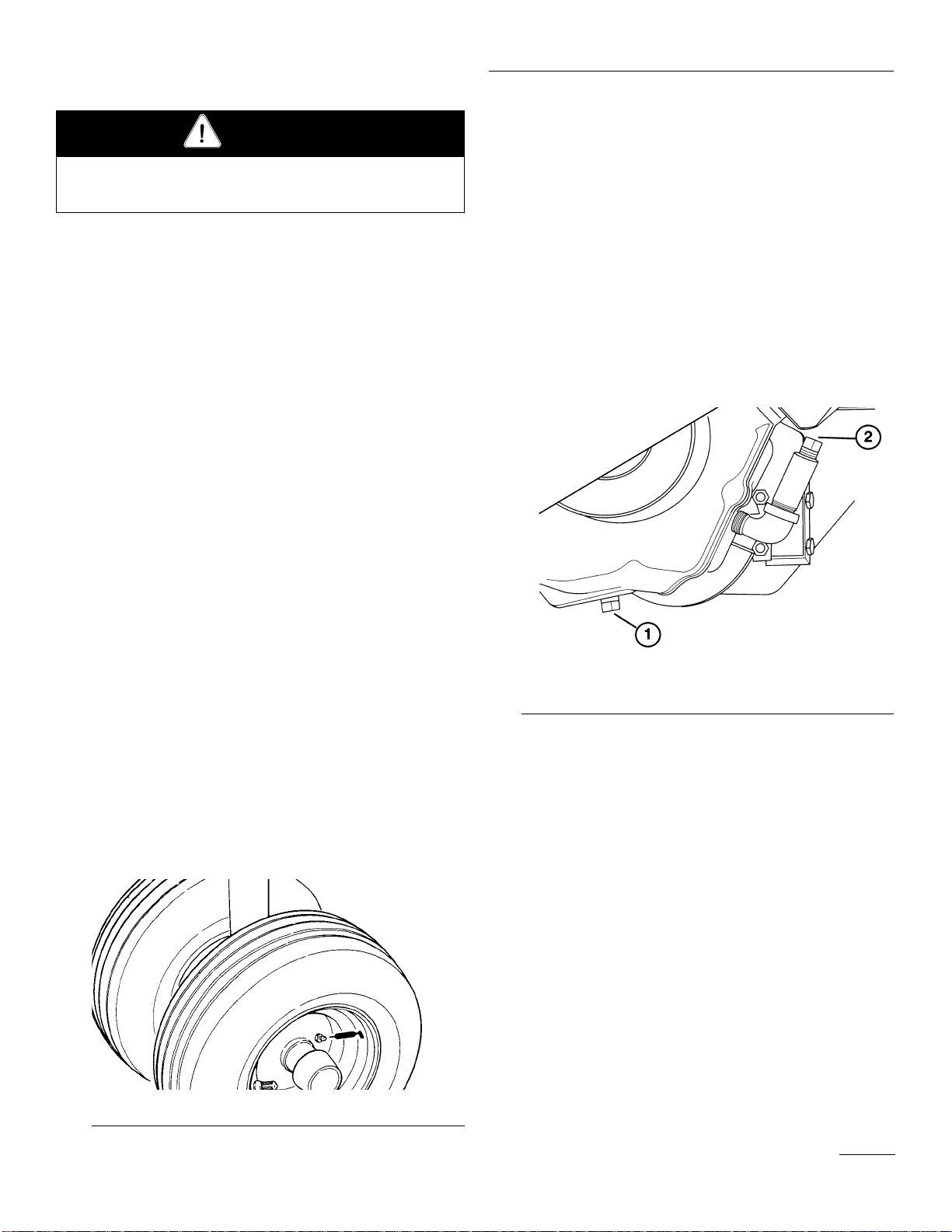
CHANGINGTRANSAXLE OIL
Each year oil in transaxle must be changed. If possible,
run the machine just before changing oil. Warm oil flows
more freely and carries more contaminants than cold oil.
1. Place a drain pan below the drain plug on the axle.
Clean the area around the drain plug (Fig. 26).
Figure 26
1. Drain plug
2. Fill plug
2. Remove the drain plug and allow oil to flow into the
drain pan. After oil is drained, install the drain plug.
3. Remove the fill plug (Fig. 26) and pour approx. 1.89 l
(64 oz.) of SAE E.P. 90 wt. oil into the extension
tube. Stop when the oil level reaches the top of the
tube.
4. To check the oil level in the future: remove the plug
and add oil as required to bring the level to the top of
the tube.
Before servicing or making adjustments to the machine,
stop engine and remove key from the switch.
CAUTION

20
Check front and rear
axle heights Check engine RPM
(3600 max, no load)
Bent, worn, loose or
plugged tines or
loose tine holder
Check gear selec-
tion
Depth-adjustment
bolts set equally
Adjust axle height
using height gauge.
(Regulate tire pres-
sure).
Adjust RPM using
tachometer.
Unplug, tighten, or
replace tines or
tighten tine holder
Coring to be done in
“L” (low) gear
Adjust depth bolts
Check freeplay in tine
arm and crank bear-
ings.
Check coring head
chain tension.
Check coring head
timing.
Loose coring head
pivot points.
Check damper
length and freeplay
in bushings and
bearings.
Replace bearings Adjust chain.Adjust timing.
Tighten or replace if
bent or damaged.
Make sure damper
is adjusted to cor-
rect specification.
Check wheel assem-
blies for loose bear-
ings or tire runout.
Replace bearings or
tires.
Hole QualityTrouble Shooting
Other manuals for GREENS AERATOR 09120
1
Table of contents
Other Toro Tiller manuals


Popular Tiller manuals by other brands

WOLSELEY
WOLSELEY Merry Tiller Major Instructions for operation and use

Gearmore
Gearmore ARENA-VATOR III AV3-4 Assembly/operators/parts manual

Cub Cadet
Cub Cadet FT 24 R Front-Tine Garden Tiller Operator's manual

Craftsman
Craftsman Incredi-Pull 316.29256 Operator's manual

AL-KO
AL-KO BF 5002R user manual

Craftsman
Craftsman 917.293482 owner's manual

MTD
MTD 216-100A Owner's operating service instruction manual

Stiga
Stiga SILEX 75-G Instructions for use

Villager
Villager VTB 375 Original instruction manual

SNOWJOE
SNOWJOE sunjoe 24V-TLR-SJG-RM Operator's manual

Craftsman
Craftsman 247.29933 Operator's manual

McCulloch
McCulloch 532 43 21-09 Operator's manual


