Toro 58604 User manual

FormNo.3454-794RevA
FrontTineTiller/Cultivator
58604
Motoazada
58604
Motoculteuràdents/cultivateuravant
58604
www.T oro.com.*3454-794*


FormNo.3454-791RevA
FrontTineTiller/Cultivator
ModelNo.58604—SerialNo.322006941andUp
Registeratwww.Toro.com.
OriginalInstructions(EN)*3454-791*

ItisaviolationofCaliforniaPublicResourceCode
Section4442or4443touseoroperatetheengineon
anyforest-covered,brush-covered,orgrass-covered
landunlesstheengineisequippedwithaspark
arrester,asdenedinSection4442,maintainedin
effectiveworkingorderortheengineisconstructed,
equipped,andmaintainedforthepreventionofre.
WARNING
CALIFORNIA
Proposition65Warning
Theengineexhaustfromthisproduct
containschemicalsknowntotheStateof
Californiatocausecancer,birthdefects,
orotherreproductiveharm.
Useofthisproductmaycauseexposure
tochemicalsknowntotheStateof
Californiatocausecancer,birthdefects,
orotherreproductiveharm.
Introduction
Thistillerisintendedtobeusedbyresidential
homeownersorprofessional,hiredoperatorsto
breakthroughhardsoilconditionsforplantingand
cultivatinggardens.Usingthisproductforpurposes
otherthanitsintendedusecouldprovedangerousto
youandbystanders.
Readthisinformationcarefullytolearnhowtooperate
andmaintainyourproductproperlyandtoavoid
injuryandproductdamage.Youareresponsiblefor
operatingtheproductproperlyandsafely.
Visitwww.T oro.comformoreinformation,including
safetytips,trainingmaterials,accessoryinformation,
helpndingadealer,ortoregisteryourproduct.
Wheneveryouneedservice,genuineToroparts,or
additionalinformation,contactanAuthorizedService
DealerorT oroCustomerServiceandhavethemodel
andserialnumbersofyourproductready.Figure1
identiesthelocationofthemodelandserialnumbers
ontheproduct.Writethenumbersinthespace
provided.
g357999
Figure1
1.Modelandserialnumberlocation
ModelNo.
SerialNo.
Thismanualidentiespotentialhazardsandhas
safetymessagesidentiedbythesafety-alertsymbol
(Figure2),whichsignalsahazardthatmaycause
seriousinjuryordeathifyoudonotfollowthe
recommendedprecautions.
g000502
Figure2
Safety-alertsymbol
Thismanualuses2wordstohighlightinformation.
Importantcallsattentiontospecialmechanical
informationandNoteemphasizesgeneralinformation
worthyofspecialattention.
©2022—TheToro®Company
8111LyndaleAvenueSouth
Bloomington,MN554202
Contactusatwww.Toro.com.
PrintedintheUSA
AllRightsReserved

Contents
Safety.......................................................................3
GeneralSafety...................................................3
SafetyandInstructionalDecals..........................4
Setup........................................................................6
1InstallingtheTines...........................................7
2InstallingtheLowerHandlebarAssembly
andShields.....................................................9
3InstallingtheUpperHandlebars.....................10
4InstallingtheDragStake.................................11
5ConnectingtheEngineSwitchCable..............12
6AddingOiltotheEngine.................................12
ProductOverview...................................................13
Controls...........................................................13
Specications..................................................13
BeforeOperation.................................................14
BeforeOperationSafety...................................14
AddingFuel......................................................15
ChangingtheTineConguration......................15
AdjustingtheHandlebars..................................17
PerformingDailyMaintenance..........................17
DuringOperation.................................................17
DuringOperationSafety...................................17
StartingtheMachine.........................................18
ShuttingOfftheEngine.....................................18
AdjustingtheDragStake..................................19
TillingSoil.........................................................19
AfterOperation....................................................19
AfterOperationSafety......................................19
Maintenance...........................................................20
MaintenanceSafety..........................................20
RecommendedMaintenanceSchedule(s)...........20
Pre-MaintenanceProcedures..............................21
PreparingforMaintenance...............................21
EngineMaintenance...........................................21
ServicingtheAirCleaner..................................21
ServicingtheEngineOil....................................22
ServicingtheSparkPlug...................................23
FuelSystemMaintenance...................................24
ServicingtheFuelFilter....................................24
BeltMaintenance................................................25
CheckingandAdjustingtheBeltTension...........25
ReplacingtheDriveBelt...................................26
Cleaning..............................................................27
CleaningtheTineAxleShaft.............................27
Storage...................................................................27
StorageSafety..................................................27
StoringtheMachine..........................................27
Troubleshooting......................................................29
Safety
Thismachinehasbeendesignedinaccordancewith
ANSIB71.8-2016.
DANGER
Theremaybeburiedutilitylinesinthework
area.Diggingintothemmaycauseashock
oranexplosion.
Havethepropertyorworkareamarkedfor
buriedlinesanddonotdiginmarkedareas.
Contactyourlocalmarkingserviceorutility
companytohavethepropertymarked(for
example,intheUS,call811forthenationwide
markingservice).
GeneralSafety
Thisproductiscapableofamputatinghandsand
feetandofthrowingobjects.Alwaysfollowallsafety
instructionstoavoidseriouspersonalinjuryordeath.
•Read,understand,andfollowtheinstructions
andwarningsinthisOperator’sManualandon
themachineandattachmentsbeforestartingthe
engine.
•Bethoroughlyfamiliarwiththecontrolsandthe
properuseoftheequipment.Knowhowtostop
themachineanddisengagethecontrolsquickly.
•Donotputyourhands,feet,otherbodyparts,or
clothingnearorundertherotatingtinesorother
movingpartsofthemachine.
•Donotoperatethemachinewithoutallproper
shields,guards,andothersafetyprotective
devicesinplaceandfunctioningproperlyonthe
machine.
•Keepbystanders,especiallysmallchildren,and
petsoutoftheoperatingarea.
•Donotallowchildrentooperatethemachine.
Allowonlypeoplewhoareresponsible,trained,
familiarwiththeinstructions,andphysically
capabletooperatethemachine.
•Shutoffthemachineandwaitforallmovingparts
tostopbeforeyouleavetheoperator’sposition.
Disconnectthespark-plugwire,keepitawayfrom
theplugtopreventaccidentalstarting,andallow
themachinetocoolbeforeadjusting,fueling,
unclogging,servicing,cleaning,orstoringthe
machine.
Improperlyusingormaintainingthismachinecan
resultininjury.T oreducethepotentialforinjury,
complywiththesesafetyinstructionsandalways
payattentiontothesafety-alertsymbol,which
meansCaution,Warning,orDanger—personalsafety
3

instruction.Failuretocomplywiththeseinstructions
mayresultinpersonalinjuryordeath.
SafetyandInstructionalDecals
Safetydecalsandinstructionsareeasilyvisibletotheoperatorandarelocatednearanyarea
ofpotentialdanger.Replaceanydecalthatisdamagedormissing.
decal133-8062
133-8062
decal144-4848
144-4848
1.Squeezethethrottletoengagethetines.
decal144-4853
144-4853
1.Engine—shutoff
decal144-4872
144-4872
1.Tostartthemachine,movetheswitchtotheONposition,
engagethechoke,placeonehandonthemachineand
pulltherecoilhandle,andmovethechokelevertotheRUN
position.
decal144-4873
144-4873
1.Warning—readthe
Operator’sManual.
3.Removingthe
shields—removethe
handknobs,rotatethe
handlebarsback,and
removethesideshields.
2.Thrownobject
hazard—keepshields
inplacewhenoutertines
areinstalled.
4

decal144-4874
144-4874
1.Warning—readthe
Operator’sManual.
3.Installingthe
shields—slidetheside
shieldon,raisethe
handlebars,andinstallthe
handknob.
2.Thrownobject
hazard—keepshields
inplacewhenoutertines
areinstalled.
decal148-4868
148-4868
1.Warning—readtheOperator’sManual.6.Warning—lookbehindyouwhenoperatingthemachinein
reverse.
2.Warning—alloperatorsshouldbetrainedbeforeoperating
themachine.
7.Warning—donotoperateoverburiedlines.
3.Warning—keepbystandersaway.8.Warning—keepfeetawayfrommovingparts.
4.Warning—stayawayfrommovingparts;keepallguardsin
place.
9.Warning—shutofftheengineanddisconnectthespark
plugandreadtheOperator’sManualbeforeperforming
maintenance.
5.Entanglementhazard,belt—stayawayfrommovingparts.
5

Setup
LooseParts
Usethechartbelowtoverifythatallpartshavebeenshipped.
ProcedureDescriptionQty.Use
Leftoutertineset1
Rightoutertineset1
Tineshaftsleeve2
Locknut(M10)2
Lockwasher2
1
Bolt(M10x45mm)2
Installthetinesandshields.
Locknut(M8)2
Washer2
Hexbolt(M8x40mm)2
Leftsideshield1
Rightsideshield1
2
Pulleyboxcover1
Installthelowerhandlebarassembly
andshields.
Bolt(M8x40mm)4
Bolt(M6x40mm)4
Washer4
Locknut(M8)4
Locknut(M6)4
Lefthandlebar1
Middledashpanel1
3
Righthandlebar1
Assemblethemachine.
Lockpin1
4Dragstake1Installthedragstake.
5Nopartsrequired–Connecttheengineswitchcable.
6Engineoil1Addingoiltotheengine.
6

1
InstallingtheTines
Partsneededforthisprocedure:
1Leftoutertineset
1Rightoutertineset
2Tineshaftsleeve
2Locknut(M10)
2Lockwasher
2Bolt(M10x45mm)
Procedure
WARNING
Whentheoutertinesareinstalled,operating
themachinewithoutthesideshieldscould
exposeyouorotherstotinecontact,causing
injuryordeath.
•Alwaysinstallthesideshieldswhenever
theoutertinesareinstalled.
•Neverputyourhandsorfeetunderthe
machine.
1.Removethehandknobboltsfrombothsides
ofthetiller.Cutthecabletiesfromthelower
handlebarassemblyandseparateitfromthe
pulleybox.
g395597
Figure3
1.Handknob
7

2.Removethelockpinfrom1tinesetandslideoff
theoutertine.Rotateitandslideitontoalign
withthesecondholeoftheinnertine.Secureit
withthelockpin.
Repeatthisstepfortheothertineset.
Important:Installthelockpinfromthefront
ofthetillersothatthewirehingesoverthe
topofthetinepipeandlatchestothepinon
therearofthetine,asshowninFigure5.
g395577
Figure4
g358135
Figure5
1.Wirehingepoint
3.Ensurethatthearrowsonthelefttinesetfollow
forwardrotationandslidethesetoverthetine
shaftsleeve.Alignthemountingholesand
securethetinesettothemachine.
Repeatthisstepfortherighttineset.
g395576
Figure6
1.Arrowfollowingforward
rotation
4.Lockwasher
2.Locknut(M10)5.Bolt(M10x45mm)
3.Tineshaftsleeve
8

2
InstallingtheLower
HandlebarAssemblyand
Shields
Partsneededforthisprocedure:
2Locknut(M8)
2Washer
2Hexbolt(M8x40mm)
1Leftsideshield
1Rightsideshield
1Pulleyboxcover
Procedure
1.Alignthelowerhandlebarassemblymountholes
withthelowermountholesonthepulleyboxand
securebothsidesoftheassemblyasshown.
g395575
Figure7
1.Locknut—M8(2)3.Hexbolt—M8x40mm(2)
2.Washer(2)
2.Rotatethelowerhandlebarassemblyawayfrom
theengine.
g395578
Figure8
3.Foreachsideshield,aligntheshieldgrooves
withthecentertineshield,slidethesideshield
ontothecentertineshield,andpushituntilyou
hear/feelitclickintoplace.Ensurethatthe
shieldissecure.
g358168
Figure9
9

4.Rotatethelowerhandlebarassemblytoward
theenginetothedesiredpositionandinstall
thehandknobsthroughthemountholesand
tightenthem.
g358169
Figure10
5.Removethe4boltsfromthepulleyboxcover.
Placethecoverontothepulleyboxandsecure
itwiththebolts.
g395579
Figure11
1.Boltsfrompulleyboxcover
(4)
2.Pulleyboxcover
3
InstallingtheUpper
Handlebars
Partsneededforthisprocedure:
4Bolt(M8x40mm)
4Bolt(M6x40mm)
4Washer
4Locknut(M8)
4Locknut(M6)
1Lefthandlebar
1Middledashpanel
1Righthandlebar
Procedure
1.Alignthe2righthandlebarmountholeswith
thelowerhandlebarmountholesatthedesired
heightandsecureitasshown.Repeatforthe
lefthandlebar.
g358243
Figure12
1.Righthandlebar4.Washer
2.Lefthandlebar5.Bolt—M8x40mm(2)
3.Nut—M8(2)
10

2.Installthemiddledashpanel.Routetheengine
switchcablethroughtheholeontheleftsideof
thepanelasshowninFigure14.
g358244
Figure13
1.Bolt—M6x40mm(4)3.Drivecable
2.Middledashpanel4.Nut—M6(4)
g361564
Figure14
3.Tightenallfasteners.
4.Ifdesired,securethedrivecableusingacable
tie.
5.InserttheZ-bendendofthedrivecableintothe
middleholeofthedrive-controllever.
Note:Ensurethatthereisnoexcessslackin
thecableandthattheleverremainsinthefull
upposition.
g358470
Figure15
1.Drive-controlleverholes
4
InstallingtheDragStake
Partsneededforthisprocedure:
1Lockpin
1Dragstake
Procedure
Installthedragstakeatthedesiredheight;referto
AdjustingtheDragStake(page19).
g358242
Figure16
1.Dragstake2.Lockpin
11
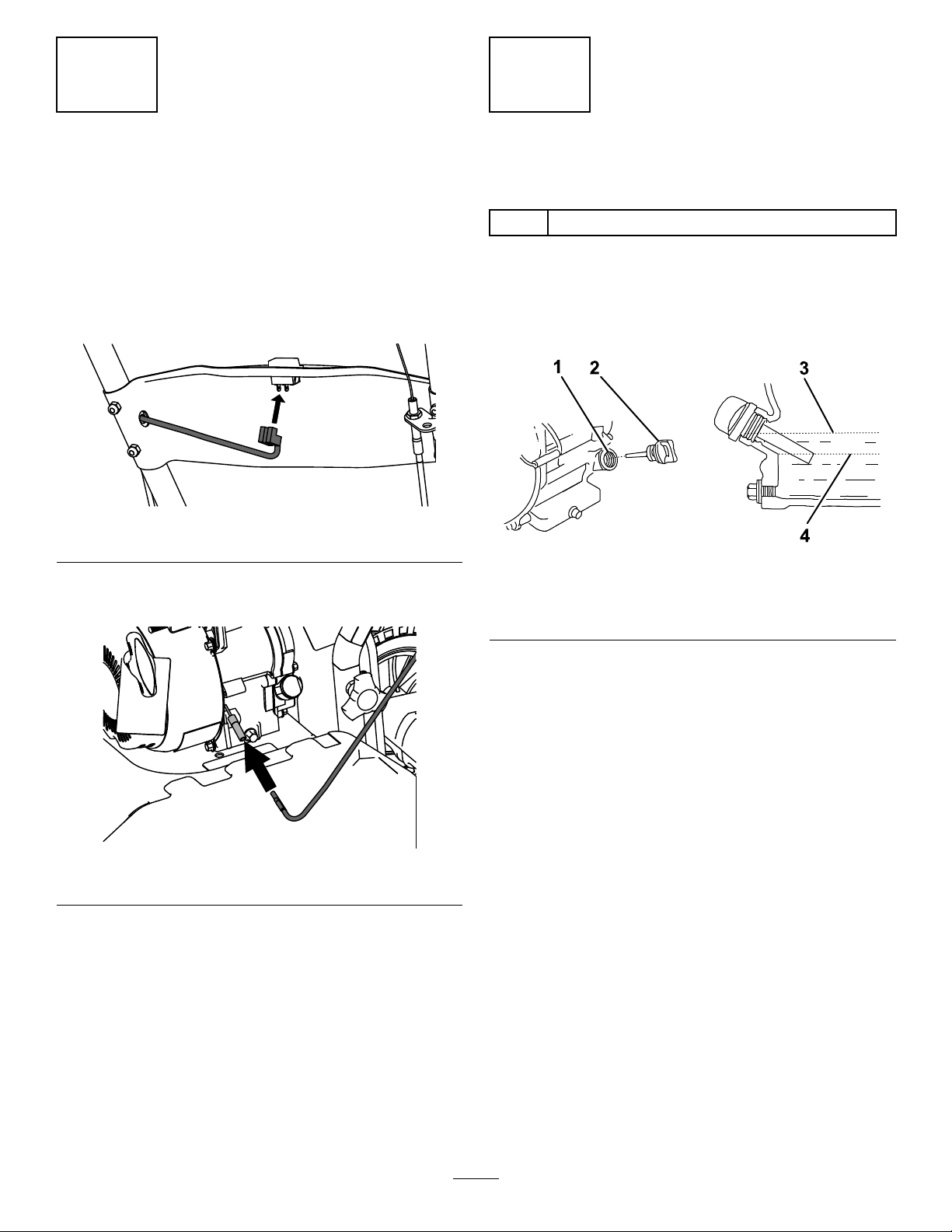
5
ConnectingtheEngine
SwitchCable
NoPartsRequired
Procedure
1.Plugtheengineswitchcableintotheengine
on/offswitch.
g361563
Figure17
2.Plugtheotherendofthecableintotheconnector
ontheengine.
g361571
Figure18
6
AddingOiltotheEngine
Partsneededforthisprocedure:
1Engineoil
Procedure
1.Movethemachinetoalevelsurface.
2.Removethedipstick.
g360549
Figure19
1.Fillertube3.Upperlimit
2.Dipstick4.Lowerlimit
3.Slowlyaddoilintothellertubeuntilthelevelis
atthetopthreadofthetube.
4.Insertthedipstickintotheoil-lltubeandtighten
it.
12

ProductOverview
g358001
Figure20
1.Throttlecontrol9.Removablesideshield
2.Chokelever10.Tines
3.Fuelcap11.Adjustablecable
4.Drive-controllever12.Pulleybox
5.Engineon/offswitch13.Wheel
6.Handgrip14.Dragstake
7.Recoilhandle15.Handlebar-adjustment
knob
8.Oil-llcap
Controls
EngineOn/OffSwitch
UsetheengineOn/Offswitchtoshuttheengineoff.
EnsurethattheswitchisintheONpositionbefore
startingtheengine.
ThrottleControl
Thethrottlecontrolstheenginespeed,andithasa
continuous-variablesetting.
Operatethemachineusingfullthrottleforbest
performance.
ChokeLever
MovethechokeleverontheenginetotheCHOKE
positionwheninitiallystartingacoldengine,then
moveitintotheRUNpositiononcestarted.
Drive-ControlLever
Squeezethedrive-controllevertothehandgripto
engagethetines.Releaseittodisengagethetines.
Specications
Specicationsanddesignaresubjecttochange
withoutnotice.
Height95cm(37.3inches)
Length127cm(50.0inches)
Width61cm(24.0inches)
Weight35.4kg(78lb)
Tillingwidth28,41,or53cm(11,16,or21
inches)
Tillingdepth28cm(11inches)
Toensureoptimumperformanceandcontinuedsafety
certicationofthemachine,useonlygenuineT oro
replacementpartsandaccessories.Replacement
partsandaccessoriesmadebyothermanufacturers
couldbedangerous,andsuchusecouldvoidthe
productwarranty.
13

Operation
Note:Determinetheleftandrightsidesofthe
machinefromthenormaloperatingposition.
BeforeOperation
BeforeOperationSafety
GeneralSafety
•Donotallowchildrenoruntrainedadultstooperate
orservicethemachine.Localregulationsmay
restricttheageoftheoperator.
•Usingthismachineisstrenuous.Youmustbein
goodphysicalconditionandmentallyalert.Ifyou
haveanyconditionthatmightbeaggravatedby
strenuouswork,checkwithyourdoctorbefore
operatingthemachine.
•Shutoffthemachineandwaitforallmovingparts
tostopbeforeyouleavetheoperator’sposition.
Disconnectthespark-plugwire,keepitawayfrom
theplugtopreventaccidentalstarting,andallow
themachinetocoolbeforeadjusting,fueling,
unclogging,servicing,cleaning,orstoringthe
machine.
•Becomefamiliarwiththesafeoperationofthe
equipment,operatorcontrols,andsafetysigns.
•Checkthatallguardsandsafetydevices,suchas
deectors,areinplaceandfunctioningproperly.
Donotoperatethemachineunlesstheyare
functioningproperly.
•Knowhowtoshutofftheenginequickly.
•Keepbystanders,especiallysmallchildren,and
petsoutoftheoperatingarea.
•Thoroughlyinspecttheareawhereyouwilluse
themachineandremoveallobjectsthatcould
interferewiththeoperationofthemachineorthat
themachinecouldthrow.
FuelSafety
•Useextremecareinhandlingfuel.Itisextremely
ammableanditsvaporsareexplosive.
•Extinguishallcigarettes,cigars,pipes,andother
sourcesofignition.
•Useonlyanapprovedfuelcontainer.
•Donotremovethefuelcaporaddfueltothetank
whiletheengineisrunningorhot.
•Allowtheenginetocoolbeforellingthefueltank.
•Donotllthefueltankindoors.
•Donotoverllthefueltank.Replacethefuelcap
andtightenitsecurelyafterfueling.Cleanup
spilledfuelbeforestartingtheengine.
•Donotllcontainersinsideavehicleoronatruck
ortrailerbedwithaplasticliner.Alwaysplace
containersontheground,awayfromthevehicle
beforelling.
•Removethemachinefromthetruckortrailer
beforellingthefueltank.Ifthisisnotpossible,
thenaddfuelfromaportablecontainerratherthan
fromafuel-dispensernozzle.
•Keepthefuel-dispensernozzleincontactwith
therimofthefueltankorcontaineropeningat
alltimesuntilfuelingiscomplete.Donotusea
nozzlelock-opendevice.
•Ifyouspillfuelonyourclothing,changeyour
clothingimmediately.
•Ifyouspillfuel,donotattempttostarttheengine;
movethemachineawayfromthespillandavoid
creatingasourceofignitionuntilthefuelvapors
havedissipated.
•Ifyoumustdrainthefueltank,doitoutdoors.
•Storefuelinafuelcontainerandkeepitoutofthe
reachofchildren.
•Donotstorethemachinewithfuelinthefueltank
orfuelcontainerwherethereisanopename,
spark,orpilotlight,suchasonawaterheateror
otherappliance.Allowtheenginetocoolbefore
storingthemachineinanyenclosure.
•Fuelisharmfulorfatalifswallowed.Long-term
exposuretovaporscancauseseriousinjuryand
illness.
–Avoidprolongedbreathingofvapors.
–Keepyourhandsandfaceawayfromthe
nozzleandthefuel-tankopening.
–Keepfuelawayfromyoureyesandskin.
14

AddingFuel
FuelSpecications
TypeUnleadedgasoline
Minimumoctanerating87(US)or91(research
octane;outsidetheUS)
EthanolNomorethan10%byvolume
MethanolNone
MTBE(methyltertiarybutyl
ether)
Lessthan15%byvolume
OilDonotaddtothefuel
Useonlyclean,fresh(nomorethan30daysold),fuel
fromareputablesource.
UsingStabilizer/Conditioner
Usefuelstabilizer/conditionerinthemachinetokeep
thefuelfreshlongerwhenusedasdirectedbythe
fuel-stabilizermanufacturer.
Important:Donotusefueladditivescontaining
methanolorethanol.
Addtheamountoffuelstabilizer/conditionertofresh
fuelasdirectedbythefuel-stabilizermanufacturer.
FillingtheFuelTank
FillthefueltankasshowninFigure21.
g230458
Figure21
ChangingtheTine
Conguration
WARNING
Whentheoutertinesareinstalled,operating
themachinewithoutthesideshieldscould
exposeyouorotherstotinecontact,causing
injuryordeath.
•Alwaysinstallthesideshieldswhenever
theoutertinesareinstalled.
•Neverputyourhandsorfeetunderthe
machine.
1.Movethemachinetoalevelsurface,shutoffthe
engine,andwaitforallmovingpartstostop.
2.Removethelockpinsfrombothsidesofthe
machine.
g358136
Figure22
1.Lockpin3.Innertine
2.Outertine
3.Installtheoutertinesperdesiredconguration:
•Widetilling—53cm(21inch)width
g358252
Figure23
15

•Narrowtilling—41cm(16inch)width
g358251
Figure24
•Narrowcultivating—28cm(11inch)width
Note:Thesideshieldsmayberemovedfor
thisconguration.Removethehandknobs
androtatethehandlebarsbacktoremove
thesideshields.
g358250
Figure25
4.Fornarrowandwidetillingcongurations,
continueasfollows:
A.Installthelockpins.
Important:Installthelockpinfrom
thefrontofthetillersothatthewire
hingesoverthetopofthetinepipeand
latchestothepinontherearofthetine.
Thetinescouldinadvertentlydetach
duringtillingifthelockpinsareinstalled
incorrectly.
g358135
Figure26
1.Wirehingepoint
B.Ensurethatthesideshieldsaresecurely
installed.
Note:Youwillhearorfeeltheshieldclick
intoplacewhenyouinstallit.
g358168
Figure27
16

AdjustingtheHandlebars
Youcanadjustthehandlebarheight2ways.
•Removethefastenersfromtheleftandright
handlebars,aligntheholesatthedesiredheight,
andsecurethehandlebars.
g358243
Figure28
1.Righthandlebar4.Washer
2.Lefthandlebar5.Bolt—M8x40mm(2)
3.Nut—M8(2)
•Removethehandknobsfromthelowerhandlebar
assembly,rotatethehandlebarstothedesired
position,andinstallthehandknobs.
g358507
Figure29
PerformingDaily
Maintenance
Beforestartingthemachineeachday,performthe
EachUse/DailyprocedureslistedinMaintenance
(page20).
DuringOperation
DuringOperationSafety
GeneralSafety
•Useyourfullattentionwhileoperatingthe
machine.Donotengageinanyactivitythat
causesdistractions;otherwise,injuryorproperty
damagemayoccur.
•Donotoperatethemachinewhileill,tired,or
undertheinuenceofalcoholordrugs.
•Wearappropriateclothing,includingeye
protection;longpants;substantial,slip-resistant
footwear;hearingprotection;andgloves.Tieback
longhairanddonotwearlooseclothingorloose
jewelry.
•Keepyourhands,feet,otherbodyparts,and
clothingawayfromrotatingtinesandmovingparts
ofthemachine.Thetinesbeginrotatingwhen
youstarttheengineandmaycontinuetorotate
momentarilyafteryoushutofftheengine.
•Starttheenginecarefullyaccordingtoinstructions
inthisOperator’sManualandwithyourfeetwell
awayfromthetines.
•Useextremecautionwhenreversingorpulling
themachinetowardyou.T oavoidgettingpinned
againstastructure,allowenoughdistanceto
reversedirectionnearawallorfence.
•Keepbystandersoutoftheoperatingarea.Keep
smallchildrenoutoftheoperatingareaandunder
thewatchfulcareofaresponsibleadultwhois
notoperatingthemachine.Stopthemachineif
anyoneentersthearea.
•Beforeyoustarttheengine,ensurethatalldrives
areinneutralandyouareintheoperatingposition.
•Operatethemachineonlyingoodvisibilityand
appropriateweatherconditions.Donotoperate
themachinewhenthereistheriskoflightning.
•Donotattempttoadjustthemachinewhilethe
engineisrunning.
•Ifthemachinestrikesanobjectorstartstovibrate
abnormally,immediatelyshutofftheengine,wait
17

forallmovingpartstostop,anddisconnectthe
wirefromthesparkplugbeforeexaminingthe
machinefordamage.Vibrationisoftenawarning
signoftrouble.Makeallnecessaryrepairsbefore
resumingoperation.
•Donotoperatethemachineathightransport
speedsonhardorslipperysurfaces.
•Lookbehindanddownandusecarewhen
reversing.
•Donotoverloadthemachinecapacityby
attemptingtotillorcultivatetoodeepandattoo
fastarate.
•Donotpickuporcarryamachinewhiletheengine
isrunning.
•Exercisecautionandbesureofyourfooting,
especiallywhenbackingup,toavoidslippingor
falling.
•Becarefulwhenoperatingthemachineinhard
ground.Thetinescancatchinthegroundand
propelthemachineforward.Ifthisoccurs,letgo
ofthemachine;donottrytorestrainit.
•Exerciseextremecautionwhencrossinggravel
surfaces.Stayalertforhiddenhazardsortrafc.
•Donotleavearunningmachineunattended.
•Shutoffthemachineandwaitforallmovingparts
tostopbeforeyouleavetheoperator’sposition.
Disconnectthespark-plugwire,keepitawayfrom
theplugtopreventaccidentalstarting,andallow
themachinetocoolbeforeadjusting,fueling,
unclogging,servicing,cleaning,orstoringthe
machine.
•Operatetheengineonlyinwell-ventilatedareas.
Exhaustgasescontaincarbonmonoxide,whichis
anodorless,deadlypoison.
•Useonlyaccessoriesandattachmentsapproved
byTheToro®Company.
•Donotchangetheenginegovernorsettingsor
overspeedtheengine.
•Alwaysbesureofyourfooting;keeparmholdon
thehandleandwalk,neverrun.
•Allowthemuferandengineareatocoolbefore
touchingthem.
•Thetinesshouldnotrotatewhentheengineis
idling;iftheydorotate,contactyourAuthorized
ServiceDealer.
•Ifanobjectbecomeslodgedinthetines,shutoff
theengine,disconnectthewirefromthespark
plug,andallowtheenginetocoolbeforeremoving
theobject.
•Donotoperatethemachineonsteepslopes.T o
preventoverturning,operatethemachineupand
downtheslope.
StartingtheMachine
1.Movetheengineon/offswitchtotheONposition.
2.MovethechokelevertotheCHOKEposition.
Note:Awarmorhotenginemaynotrequire
choking.
3.Movethethrottleleverhalfwaybetweenthe
SLOWandFASTpositions.
4.Pullthestarterhandlelightlyuntilyoufeel
resistance,thenpullthehandlebriskly.Return
thestarterhandlegently.
5.Aftertheenginestarts,graduallymovethe
chokelevertotheRUNpositionandthethrottle
levertotheFASTposition.
ShuttingOfftheEngine
1.Releasethedrive-controllever.
2.Movetheengineon/offswitchtotheOFF
position.
3.Waitforallmovingpartstostopbeforeleaving
theoperatingposition.
18
Other manuals for 58604
1
Table of contents
Languages:
Other Toro Tiller manuals


