Toro 22521 User manual

Form No. 3358-271 Rev A
Grapple RakeFor Compact Utility LoadersModel No. 22521 —Serial No. 270000001 and Up
Register your product at www.Toro.com Original Instructions (EN)

Introduction
R ead this infor mation carefully to lear n ho w to operate
and maintain y our product properly and to a v oid injur y
and product damag e . Y ou are responsible for operating
the product properly and safely .
Y ou ma y contact T oro directly at www .T oro .com for
product and accessor y infor mation, help finding a
dealer , or to register y our product.
W henev er y ou need ser vice , g en uine T oro par ts , or
additional infor mation, contact an A uthorized Ser vice
Dealer or T oro Customer Ser vice and ha v e the model
and serial n umbers of y our product ready . T he model
and serial n umbers are located on a plate on the
attac hment frame , in front of the mount plate . W rite
the n umbers in the space pro vided.
Model No.
Serial No.
T his man ual identifies potential hazards and has
safety messag es identified b y the safety aler t symbol
( Figure 1 ), whic h signals a hazard that ma y cause
serious injur y or death if y ou do not follo w the
recommended precautions .
Figure 1
1. Safety alert symbol
T his man ual uses 2 other w ords to highlight
infor mation. Impor tant calls attention to special
mec hanical infor mation and Note emphasizes g eneral
infor mation w or th y of special attention.
Contents
Introduction ......................................................... 2
Safety .................................................................. 3
Stability Ratings .............................................. 4
Safety and Instr uctional Decals . . . . . . . . . . . . . . . . . . . . . . . . 4
Product Ov er view ................................................. 5
Specifications ................................................ 5
Operation ............................................................ 6
Lifting Objects ............................................... 6
Dig ging/Raking with the Upper J a w . . . . . . . . . . . . . . . . . . 6
Dig ging with the Lo w er J a w ............................. 6
Maintenance ......................................................... 7
R ecommended Maintenance
Sc hedule(s) ..................................... 7
Greasing the Pi v ot J oints ................................. 7
Storag e ................................................................ 8
© 2007—The Toro® Company8111 Lyndale Avenue SouthBloomington, MN 55420
2
Contact us at www.Toro.com.
Printed in the USA.All Rights Reserved

Safety
Impr oper use or maintenance by the operator
or o wner can r esult in injur y . T o r educe the
potential f or injur y , compl y with these safety
instr uctions and those in the traction unit
Operator’ s Man ual . Al w ays pay attention
to the safety aler t symbol, which means
Caution , W ar ning , or Danger —per sonal
safety instr uction. F ailur e to compl y with the
instr uction may r esult in per sonal injur y or
death.
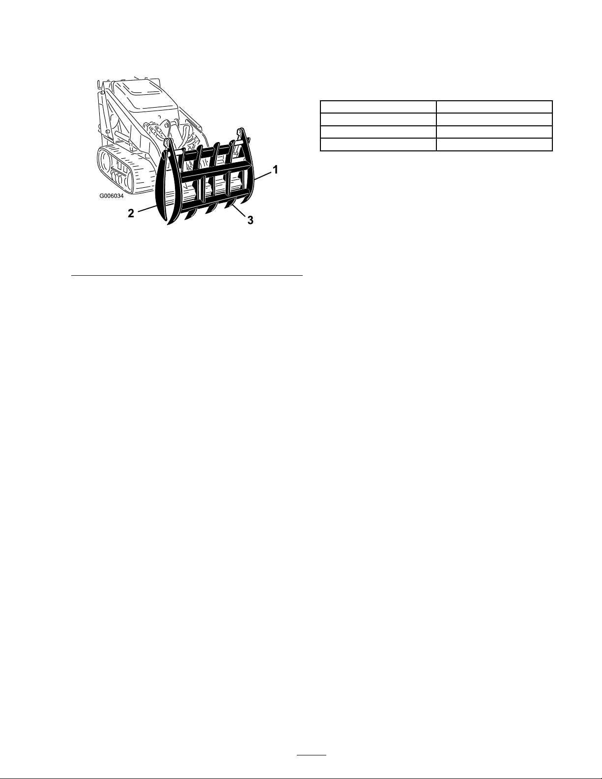
T he attachment can cr ush and br eak legs,
ar ms, and other body par ts.
• Nev er go near the attachment while it is
in operation.
• K eep all bystander s and pets a safe
distance fr om the attachment.
• Al w ays close the ja ws of the attachment
when not in use.
T her e may be buried po w er , gas, and/or
telephone lines in the w or k ar ea. Shock or
explosion may occur if y ou dig into them.
Ha v e the pr oper ty or w or k ar ea mar k ed f or
buried lines and do not dig in mar k ed ar eas.
T her e may be o v erhead po w er lines in the
w or k ar ea. Shock may occur if y ou touch a
po w er line with a tr ee or other object that
y ou ar e transpor ting .
Sur v ey and mar k the ar ea wher e ther e ar e
o v erhead po w er lines, and do not transpor t
tr ees or tall objects under the po w er lines.
W hen the engine is of f, attachments in
the raised position can g raduall y lo w er .
Someone nearby may be pinned or injur ed
by the attachment as it lo w er s.
• Al w ays lo w er the attachment lift each
time y ou shut of f the traction unit.
• Al w ays close the g rapple’ s ja ws each
time y ou shut of f the traction unit.
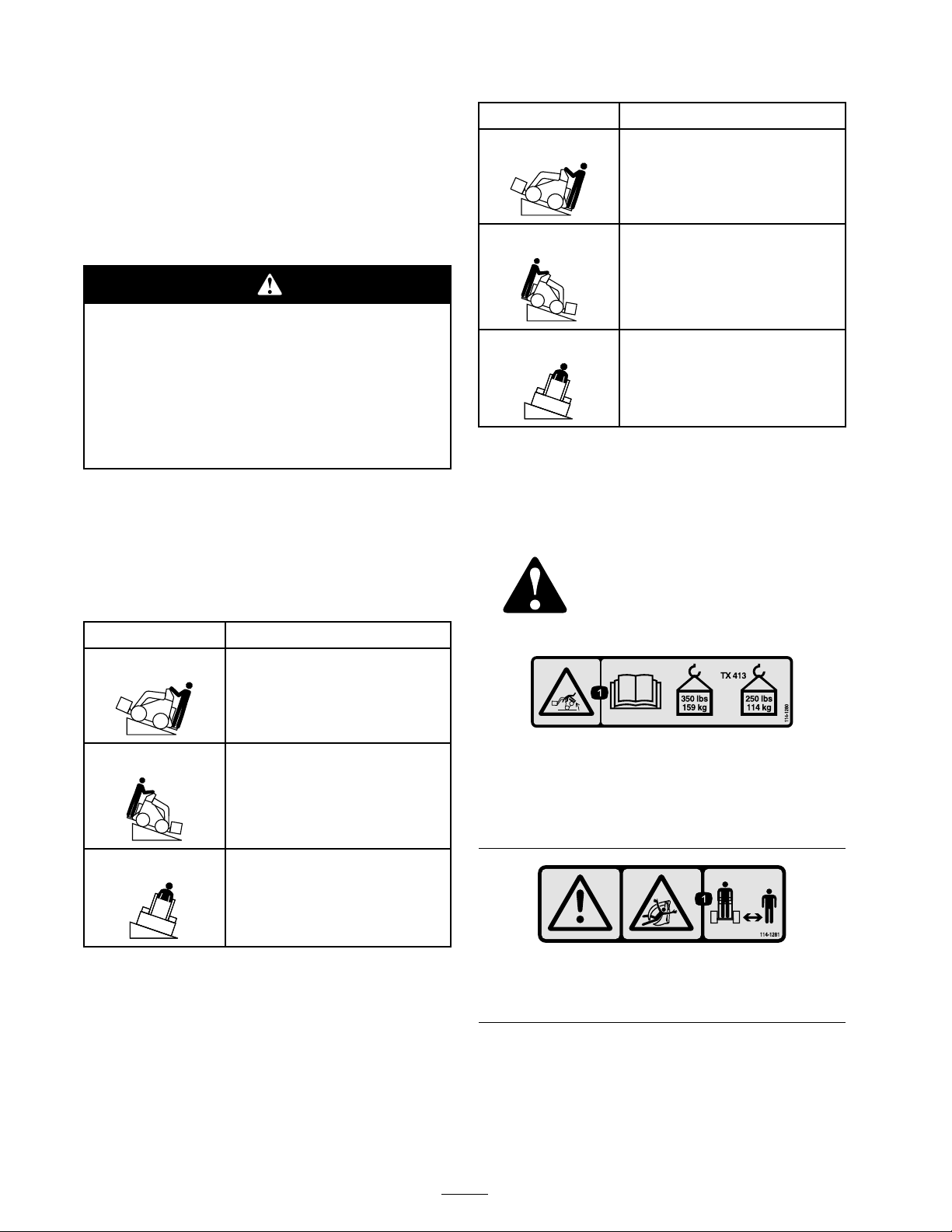
If y ou step of f of the platf or m with the
load raised, the machine could tip f orw ard.
Someone nearby may be pinned or injur ed.
Lo w er the load bef or e stepping of f of the
platf or m.
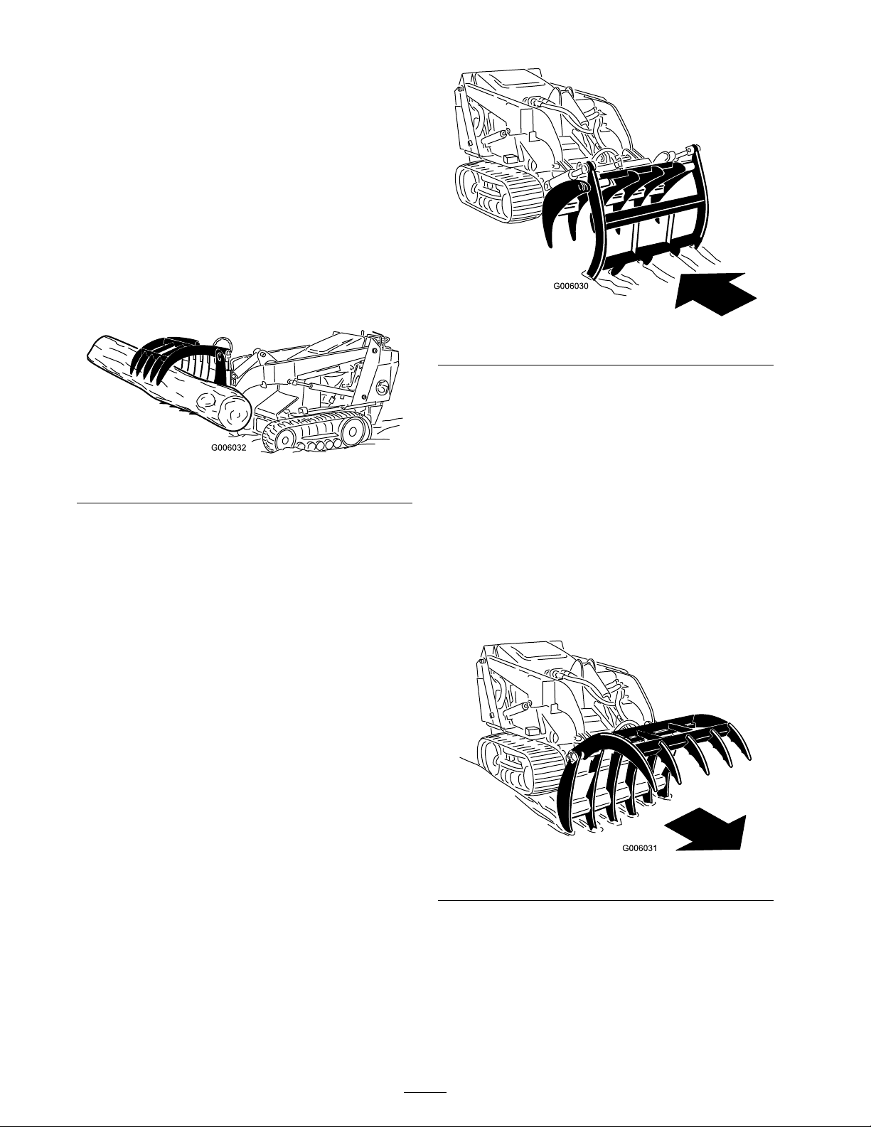
If y ou lift a long object of f center , it could
cause the machine to tip sidew ays. Someone
nearby may be pinned or injur ed.
Al w ays g ra b and lift long items near the
center .
Lifting unev en, hea vy objects can cause
the machine to become unsta ble and tip
f orw ard. Someone nearby may be pinned or
injur ed.
W hen lifting an object, k eep it as lo w to the
g r ound as possible.
W hen going up or do wn hill, the machine
could o v er tur n if the hea vy end is to w ard
the do wnhill side. Someone may be pinned
or seriousl y injur ed by the machine if it
o v er tur ns.
Operate up and do wn slopes with the hea vy
end of the machine uphill. Car r ying a load
with the attachment will mak e the fr ont end
hea vy .
3

Stability Ratings
T o deter mine the deg ree of slope y ou can tra v erse
with the attac hment installed on a traction unit,
find the stability rating for the hill position y ou
w ant to tra v el in the appropriate table belo w , then
find the deg ree of slope for the same rating and
hill position in the Stability Data section of the
traction unit Operator’ s Manual .
Ex ceeding the maximum r ecommended
slope can cause the traction unit to tip ,
cr ushing y ou or bystander s.
Do not dri v e the traction unit on a slope
steeper than the maximum r ecommended
slope, as deter mined in the f ollo wing ta bles
and the traction unit Operator’ s Man ual .
Important: If y ou ha v e a wheeled traction
unit (i.e., not a TX), use the counterw eight on
the platf or m while using the attachment, or
the traction unit will become unsta ble.
Stability With a Load
Orientation Stability Rating
Front Uphill
CRear Uphill
DSide Uphill
C
Stability Without a Load
Orientation Stability Rating
Front Uphill
DRear Uphill
CSide Uphill
C
Safety and Instructional
Decals
Safety decals and instr uctions
are easily visible to the operator
and are located near any area of
potential dang er . R e place any
decal that is damag ed or lost.
114-1280
1. Tipping hazard, exceeding rated load capacity can causeinstability—read the Operator’s Manual ; do not exceedmaximum load capacity of 350 lb (159 Kg); for TX 413models, do not exceed maximum load capacity of 250 lb(114 Kg).
114-1281
1. Warning; crushing hazard, grapple—keep bystanders a safedistance from the machine.
4

Product Overview
Figure 2
1. Upper jaw
3. Tooth2. Lower jaw
Specications
Note: Specifications and design are subject to
c hang e without notice .
Width
34.5 inches (87.6 cm)
Length
18 inches (46 cm)
Height
30 inches (76 cm)
Weight
265 lb (120 Kg)
5

Operation
Note: Alw a ys use the traction unit to lift and
mo v e the attac hment.
R efer to y our traction unit Operator’ s Manual for
procedures to install an attac hment, connect
h y draulic hoses , and remo v e an attac hment.
Lifting Objects
Use the attac hment to g rab and lift hea vy objects
suc h as logs and roc ks .
Figure 3
Nev er lift more than the rated lift capacity of
the attac hment as listed on the decals . W hen
transpor ting a load, k ee p it as close to the g round
as possible .
Important: If y ou ar e lifting mor e delicate
or hollo w items, such as crates, close the ja ws
with car e so as not to cr ush the item being
mo v ed.
Digging/Raking with theUpper Jaw
T o dig or rak e using the upper ja w , open the
ja ws all the w a y , and tilt the attac hment forw ard
until the upper ja w teeth touc h (or penetrate) the
g round. Dri v e the mac hine rearw ards . If the teeth
are on the g round, this will rak e up loose stic ks
and other debris , whic h y ou can then g rab with the
ja ws . If the teeth penetrate the g round, this will
dig fur ro ws in the ear th, breaking up the sod.
Note: Y ou can also perfor m this operation with
the ja ws closed, because the upper teeth protr ude
through the lo w er ja w .
Figure 4
Y ou can also use this method to rip out bushes .
Place the upper ja w teeth into the g round on the
far side of the bush and then close the ja ws around
the bush and roots , ripping the bush out of the
g round.
Digging with the Lower Jaw
T o dig or rak e using the lo w er ja w , open the ja ws
and lo w er the lo w er ja w teeth into the g round.
Dri v e the mac hine forw ard. T his will dig fur ro ws
in the ear th, breaking up the sod, and will also
push any debris ahead of the attac hment.
Figure 5
6

Maintenance
Recommended Maintenance Schedule(s)
Maintenance ServiceInterval
Maintenance Procedure
Before each use or daily
• Grease the pivot joints.
Before storage
• Paint chipped surfaces.
If y ou lea v e the k ey in the ignition s witch, someone could star t the engine. Accidental star ting
of the engine could seriousl y injur e y ou or other bystander s.
R emo v e the k ey fr om the ignition s witch bef or e y ou do an y maintenance.
Greasing the Pivot Joints
Grease all pi v ot joints ev er y 8 operating hours and
immediately after ev er y w ashing .
Gr ease T ype: General-pur pose g rease .
1. Lo w er the loader ar ms , close the g rapple ja ws ,
and stop the engine . R emo v e the k ey .
2. Clean the g rease fittings with a rag .
3. Connect a g rease gun to eac h fitting ( Figure 6 ).
G006033
Figure 6
4. Pump g rease into the fittings until g rease begins
to ooze out of the bearings (appro ximately 3
pumps).
5. Wipe up any ex cess g rease .
7

Storage
1. Before long ter m storag e , w ash the attac hment
with mild deterg ent and w ater to remo v e dir t
and g rime .
2. P aint all scratc hed or bare metal surfaces . P aint
is a v ailable from y our A uthorized Ser vice
Dealer .
3. Store the attac hment in a clean, dr y g arag e or
storag e area. Co v er it to protect it and k ee p
it clean.
8


The Toro Dingo® Product Line WarrantyA One-Year Limited Warranty
Conditions and Products CoveredThe Toro® Company and its afliate, Toro Warranty Company,pursuant to an agreement between them, jointly warrant yourToro Dingo Product (“Product”) to be free from defects inmaterials or workmanship. The following time periods apply fromthe date the Product is delivered to the original retail purchaser:
Products Warranty Period
All traction units andattachments
1 year or 1000 operationalhours, whichever occurs rstAll engines
2 years
Where a warrantable condition exists, we will repair the Productat no cost to you including diagnosis, labor, and parts.
Instructions for Obtaining Warranty ServiceIf you think that your Toro Product contains a defect in materialsor workmanship, follow this procedure:
1. Contact any Authorized Dingo Service Dealer to arrangeservice at their dealership. To locate a dealer convenient toyou, access our website at www.Toro.com. U.S. Customersmay also call 800-348-2424.
2. Bring the product and your proof of purchase (sales receipt)to the Service Dealer.If for any reason you are dissatised with the Service Dealer’sanalysis or with the assistance provided, contact us at:
LCB Customer Service Department
Toro Warranty Company
8111 Lyndale Avenue South
Bloomington, MN 55420-1196
Toll Free: 888-577-7466 (U.S. customers)Toll Free: 877-484-9255 (Canada customers)
Owner ResponsibilitiesYou must maintain your Toro Product by following themaintenance procedures described in the Operator’s Manual .Such routine maintenance, whether performed by a dealer orby you, is at your expense. Parts scheduled for replacement asrequired maintenance (“Maintenance Parts”), are warranted forthe period of time up to the scheduled replacement time for thatpart. Failure to perform required maintenance and adjustmentscan be grounds for disallowing a warranty claim.
Items and Conditions Not CoveredNot all product failures or malfunctions that occur during thewarranty period are defects in materials or workmanship. Thisexpress warranty does not cover the following:
•Product failures which result from the use of non-Tororeplacement parts, or from installation and use of add-on,modied, or unapproved accessories
•Product failures which result from failure to perform requiredmaintenance and/or adjustments
•Product failures which result from operating the Product inan abusive, negligent or reckless manner
•Parts subject to consumption through use unless found tobe defective. Examples of parts which are consumed, orused up, during normal Product operation include, but arenot limited to, digging teeth, tines, spark plugs, tires, tracks,lters, chains, etc.
•Failures caused by outside inuence. Items considered to beoutside inuence include, but are not limited to, weather,storage practices, contamination, use of unapprovedcoolants, lubricants, additives, or chemicals, etc.
•Normal “wear and tear” items. Normal “wear and tear”includes, but is not limited to, worn painted surfaces,scratched decals or windows, etc.
•Any component covered by a separate manufacturer’swarranty
•Pickup and delivery charges
General ConditionsRepair by an Authorized Toro Service Dealer is your sole remedyunder this warranty.
Neither The Toro® Company nor Toro Warranty Company is liablefor indirect, incidental or consequential damages in connectionwith the use of the Toro Products covered by this warranty,including any cost or expense of providing substitute equipmentor service during reasonable periods of malfunction or non-usepending completion of repairs under this warranty.
Some states do not allow exclusions of incidental or consequentialdamages, or limitations on how long an implied warranty lasts,so the above exclusions and limitations may not apply to you.
This warranty gives you specic legal rights, and you may alsohave other rights which vary from state to state.
Except for the Emissions warranty referenced below, if applicable,there is no other express warranty. All implied warranties ofmerchantability and tness for use are limited to the durationof this express warranty.
Note to California residents: The Emissions Control Systemon your Product may be covered by a separate warranty meetingrequirements established by the U.S. Environmental ProtectionAgency (EPA) or the California Air Resources Board (CARB). Thehour limitations set forth above do not apply to the EmissionsControl System Warranty. Refer to the California EmissionControl Warranty Statement printed in you operator’s manualor contained in the engine manufacturer’s documentation fordetails.
Countries Other than the United States or CanadaCustomers who have purchased Toro products exported from the United States or Canada should contact their Toro Distributor(Dealer) to obtain guarantee policies for your country, province, or state. If for any reason you are dissatised with your Distributor’sservice or have difculty obtaining guarantee information, contact the Toro importer. If all other remedies fail, you may contact usat Toro Warranty Company.
374-0047 Rev A
Other manuals for 22521
1
Table of contents
Other Toro Tractor Accessories manuals

Toro
Toro 08733 User manual

Toro
Toro Wheel Horse XT Series User manual

Toro
Toro 08720 User manual

Toro
Toro 23172 User manual

Toro
Toro Greensmaster TriFlex 3300 Series User manual

Toro
Toro 136-8545 User manual

Toro
Toro 04720 User manual

Toro
Toro 25427 User manual

Toro
Toro 98-9880 User manual

Toro
Toro 119-9604 User manual

Toro
Toro 08752 User manual

Toro
Toro 30517 Instruction Manual

Toro
Toro 30728 User manual

Toro
Toro 04479 User manual

Toro
Toro Wheel Horse 79361 User manual

Toro
Toro 79181 User manual

Toro
Toro Greensmaster 04654 Series User manual

Toro
Toro 22414 User manual

Toro
Toro Z MASTER 79402 User manual

Toro
Toro 79362 User manual