manuals.online logo
Brands
  1. Home
  2. •
  3. Brands
  4. •
  5. Toshiba
  6. •
  7. Printer
  8. •
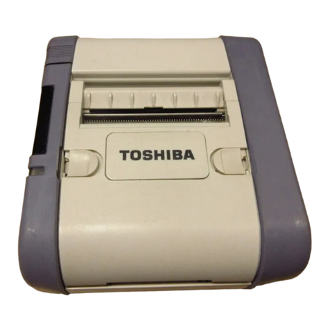
  9. Toshiba B-EP2DL Series User manual

Toshiba B-EP2DL Series User manual

PRINTED IN JAPAN
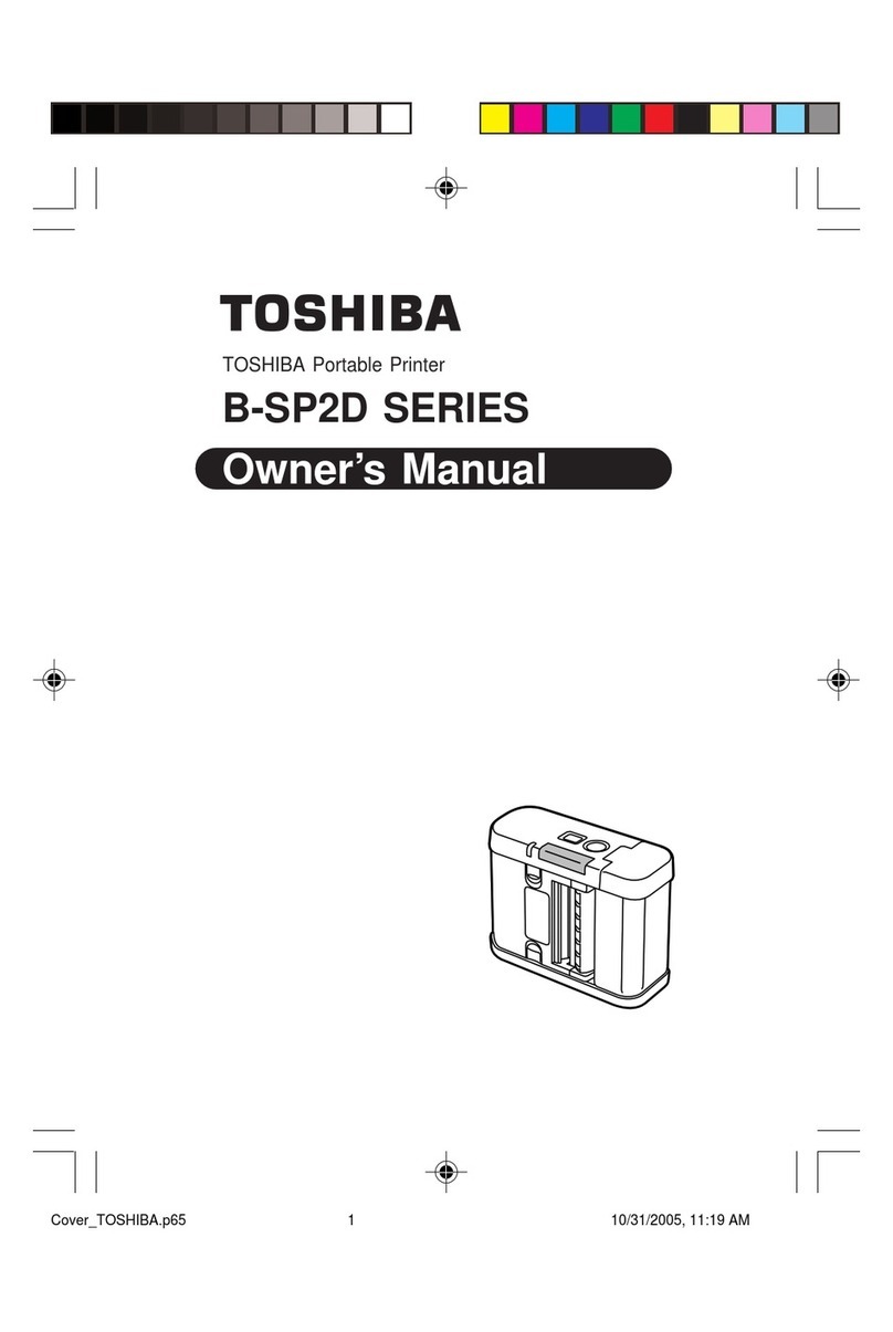
TOSHIBA Thermal Printer
B-EP2DL/EP4DL SERIES
Document No. EO15-33005
Original Sep., 2008
(Revised )
O
p
tion Installation Manual
PRELIMINARY
Linerless Label Kit, which are under development
as of November 7, 2008, could be changed.
EO15-33005
TABLE OF CONTENTS
Page
1. Linerless Label Kit: B-EP902-LL-QM-R /B-EP904-LL-QM-R----------------------------------------1- 1
2. Wireless LAN Board: B-EP700-WLAN-QM-R------------------------------------------------------------2- 1
3. Bluetooth Module: B-EP700-BLTH-QM-R ----------------------------------------------------------------3- 1
CAUTION!
1. This manual may not be copied in whole or in part without prior written permission of TOSHIBA
TEC.
2. The contents of this manual may be changed without notification.
Copyright © 2008
by TOSHIBA TEC CORPORATION
A
ll Rights Reserved
570 Ohito, Izunokuni-shi, Shizuoka-ken, JAPAN
INSTALLATION PROCEDURE FOR OPTIONAL EQUIPMENT EO15-33005
1. Linerless Label Kit: B-EP902-LL-QM-R/B-EP904-LL-QM-R
1- 1
INSTALLATION PROCEDURE FOR OPTIONAL
EQUIPMENT
1. Linerless Label Kit: B-EP902-LL-QM-R/B-EP904-LL-QM-R
The B-EP902-LL-QM-R/B-EP904-LL-QM-R linerless label kit is a platen roller unit designed for enabling the
B-EP2DL/B-EP4DL series portable printer to issue linerless labels.
The B-EP902-LL-QM-R is for the B-EP2DL series, and the B-EP904-LL-QM-R is for the B-EP4DL series,
respectively.
•Packing List
The following parts are supplied with the kit. Make sure you have all items shown below.
Linerless label kit (1 pc.)
Installation Manual (1 copy)
WARNING!
1. Turn the printer power off and disconnect the power cord before installing an optional
equipment.
2. Be careful not to pinch your fingers or hands with the covers.
3. Be careful not to injure your fingers when installing the cutter module.
WARNING
!
1. Follow all manual instructions. Failure to do so could create safety hazards such as fire or
electrocution.
• Manual instructions must be followed when installing option kits or adding cables to avoid
system failures and to insure proper performance and operation
• Failure to follow manual instructions or any unauthorized modifications, substitution or change
to this product will void the limited product warranty.
2. Turn the power off and remove the battery pack from the printer before installing this kit. Failure to
do this may cause electric shock or injury.
3. Do not touch the print head and around it immediately after printing, as doing so may cause you to
get burned.
CAUTION!
• Do not drop or hit this kit hard, or it may be broken.
• Do not push the strip shaft too hard. If it is deformed, feed failures may result.
• Do not use any chemical solvent such as thinner or benzene to clean the roller, as doing so
may cause feed failures.
• Do not damage the roller with a sharp object. Doing so may cause print failures or feed failures.
INSTALLATION PROCEDURE FOR OPTIONAL EQUIPMENT EO15-33005
1. Linerless Label Kit: B-EP902-LL-QM-R/B-EP904-LL-QM-R
1- 2
•Required Tools
●Slotted jewellers screw driver
●Phillips head jewellers screw driver (Only for installing the B-EP904-LL-QM-R)
•Installation Procedure
1. Turn the printer power off and remove the battery pack from the printer.
2. Press the top cover open button and fully open the top cover.
3. Remove the inner top cover using the following procedure.
(For the B-EP2DL Series)
Release the two hooks on the right side of the inner cover with a slotted jewellers screw driver and
remove the inner cover from the top cover.
If the inner cover cannot be removed easily, release the left side hooks, also.
(For the B-EP4DL Series)
(1) Remove the two screws securing the inner cover with a Phillips head jewellers screw driver.
(2) Release the two hooks on the right side of the inner cover with a slotted jewellers screw driver.
(3) Release the three hooks on the left side of the inner cover with a slotted jewellers screw driver,
and remove the inner cover from the top cover.
NOTE: Do not push the hooks too hard, as doing so may break the hooks.
Top Cover
Hook
Hook
Inner Cover
Top Cover
Hook
Hook
Inner Cover
M-2 x 5 Screw
Hook
INSTALLATION PROCEDURE FOR OPTIONAL EQUIPMENT EO15-33005
1. Linerless Label Kit: B-EP902-LL-QM-R/B-EP904-LL-QM-R
1- 3
4. While pushing the hook on the right side of the platen unit with a slotted jewellers screw driver, remove
the platen unit upward from the printer.
NOTES: 1. Do not push the hook too hard, as doing so may break the hook.
2. Keep the removed platen unit safe.
5. Install the linerless label kit in place of the platen unit. First, fit the hook of the platen gear side, then
one on the other side.
6 Attach the inner cover in place.
(For the B-EP2DL Series)
First, fit the left side of the inner cover, then the right side.
(For the B-EP4DL Series)
(1) First, fit the left side of the inner cover, then the right side.
(2) Secure the inner cover with the two screws which were removed in Step 3.
Gear
Hook
Platen Unit
Linerless Label Kit
Top Cover
Hook
Hook
Inner Cover
Top Cover
Inner Cover
Strip Shaft
M-2 x 5 Screw
INSTALLATION PROCEDURE FOR OPTIONAL EQUIPMENT EO15-33005
1. Linerless Label Kit: B-EP902-LL-QM-R/B-EP904-LL-QM-R
1- 4
7 Make sure that the top cover can be closed completely.
8 Change the printer setting to activate the linerless label kit.
•Changing the Printer Setting
Use the following procedure to change the printer setting to activate the linerless label kit.
1. Load the battery pack in the printer.
2. While holding down the [FEED] button, press the
[POWER] button.
The printer starts up in the system mode.
3. Press the [PAUSE] button twice.
4. Press the [POWER] button until “LINERLESS XXX” is
displayed on the LCD.
5. When the “LINERLESS OFF” is displayed, press the
[PAUSE] button to set this parameter to ON.
When the “LINERLESS ON” is displayed, go to Step 6
without pressing the [PAUSE] button.
6. Press the [POWER] button until “<2>MODE SETTING”
is displayed on the LCD.
7. Press the [FEED] button twice until “<0>SHUTDOWN”
is displayed on the LCD.
8. Press the [POWER] button to turn the printer power off.
The printer setting change is completed.
<0>SHUTDOWN
<2>MODE SETTING
LINERLESS OFF
LINERLESS ON
<2>MODE SETTING
<0>SHUTDOWN
INSTALLATION PROCEDURE FOR OPTIONAL EQUIPMENT EO15-33005
2. Wireless LAN Board: B-EP700-WLAN-QM-R
2- 1
2. Wireless LAN Board: B-EP700-WLAN-QM-R
Thank you for purchasing TOSHIBA wireless LAN kit, B-EP700-WLAN-QM-R.
The B-EP700-WLAN-QM-R is an optional wireless LAN interface board for the B-EP2D/EP4D Series.
The pictures used in this document are those of the B-EP4D, but the installation procedure is common with
the B-EP2D unless otherwise noted.
•Packing List
The following parts are supplied with the kit. Make sure you have all items shown below.
Wireless LAN Board (1 pc.)
FPC cable (2 pcs.)
Installation Manual (1 copy)
•Installation Procedure
1. Turn off the printer.
2. Slide the battery lever in the direction of the arrow, and remove the battery pack from the printer.
3. Remove the four tapping screws (T-3x10) from the bottom cover.
1. Follow all manual instructions. Failure to do so could create safety hazards such as fire or
electrocution.
• Manual instructions must be followed when installing option kits or adding cables to avoid
system failures and to insure proper performance and operation.
• Failure to follow manual instructions or any unauthorized modifications, substitution or change to
this product will void the limited product warranty.
2. Turn the power off and remove the battery before installing the wireless LAN module.
3. Be careful not to
p
inch
y
our fin
g
ers or hands with the covers.
WARNING!
Battery Lever
Battery Pack T-3x10 Tapping Screw
T-3x10 Tapping Screw
INSTALLATION PROCEDURE FOR OPTIONAL EQUIPMENT EO15-33005
2. Wireless LAN Board: B-EP700-WLAN-QM-R
2- 2
4. Press the top cover open button to open the top cover.
5. Remove the left side cover in the direction of the arrow.
NOTE: The gears shown in the picture below is not secured and is easily removed. Be careful
not to drop and break or lose it.
6. Remove the right side cover and the front cover in the direction of the arrow, respectively.
Top Cover
Top Cover Open Button Left Side Cover
B-EP4D B-EP2D
Gea
r
Gear
Gea
r
Right Side Cover
Front Cove
r
INSTALLATION PROCEDURE FOR OPTIONAL EQUIPMENT EO15-33005
2. Wireless LAN Board: B-EP700-WLAN-QM-R
2- 3
NOTE: As the fold of the FPC cable differs depending on the printer, please connect a correct one to the
printer.
B-EP4D Series
B-EP2D Series
FCC Cable Forming Indication Figure
15 2614.5
150
20 22 37.5 14
1
7.5 15.5 32.5 20 29.5 22.5 8.5 14
FCC Cable Forming Indication Figure
FCC Cable Folding Directions
7.5
20
46.5
15
29.5
6.5
16
8.5
Connect this terminal to
the Wireless LAN module.
Connect this terminal to
the MAIN PC Board.
Connect this terminal to
the MAIN PC Board.
(Unit: mm)
: Valley Fold
: Mountain Fold
15 20
150
7.5 20.5
28.5 14.5 34.5 21.5 16
168.5
6.529.5
1546.5
20
26
1
14
37.5
22
14.5
7.5
15
15.5
FCC Cable Folding Directions
Connect this terminal to
the Wireless LAN module.
INSTALLATION PROCEDURE FOR OPTIONAL EQUIPMENT EO15-33005
2. Wireless LAN Board: B-EP700-WLAN-QM-R
2- 4
7. Connect the FPC cable to the wireless LAN module.
8. Pass the FPC cable through the slot, as shown in the picture. (B-EP4D model only)
9. Secure the ground wire with the Tapping screw (T-2x6) which secures the driver PC board.
Wireless LAN Module FPC Cable
Ground
wire
FPC Cable Slot
B-EP2D
B-EP4D Driver PC Board
Ground Wire
T-2x6 Tapping Screw Driver PC Board
Ground Wire
T-2x6 Tapping Screw
INSTALLATION PROCEDURE FOR OPTIONAL EQUIPMENT EO15-33005
2. Wireless LAN Board: B-EP700-WLAN-QM-R
2- 5
10. Connect the FPC cable to the connector CN301 on the Main PC board.
11. Fit the wireless LAN module into the following position.
NOTE: Pass the FPC cable and the ground wire so that they do not get caught on the gears or by
the cover.
B-EP2D
Wireless LAN Module
B-EP4D
Wireless LAN Module
Main PC Board
FPC Cable
CN301
INSTALLATION PROCEDURE FOR OPTIONAL EQUIPMENT EO15-33005
2. Wireless LAN Board: B-EP700-WLAN-QM-R
2- 6
12. Close the front cover.
NOTES: 1. Make sure that the pins on the both sides of the front cover are fit in position, as
shown in the pictures below.
2. Do not reassemble the Front Cover while the Top Cover Open Button is pressed.
Doing so may cause the Top Cover not to open.
Pin
Front Cove
r
Top Cover Open Button
Good No Good
INSTALLATION PROCEDURE FOR OPTIONAL EQUIPMENT EO15-33005
2. Wireless LAN Board: B-EP700-WLAN-QM-R
2- 7
13. Mount the left side cover to the printer while fitting the tabs on the left side cover into the slots of the
printer enclosure.
B-EP4D Series: Fit the tabs A to D into the slot A’ to D’.
B-EP2D Series: Fit the tabs A to C into the slot A’ to C’.
NOTE: It is easy to mount the left side cover if you fit the tabs from the LCD side in order, then
secure the bottom side. Be careful not to catch the cable by the cover while reassembling.
Tab
A
Tab B Tab C Tab D
A
’
B’
C’
D’
Tab
A
Tab C
Tab B
A
’
B’
C’
Left Side Cove
r
INSTALLATION PROCEDURE FOR OPTIONAL EQUIPMENT EO15-33005
2. Wireless LAN Board: B-EP700-WLAN-QM-R
2- 8
14. Mount the right side cover to the printer while fitting the tabs on the right side cover into the slots of
the printer enclosure.
B-EP4D Series: Fit the tabs A to C into the slot A’ to C’.
B-EP2D Series: Fit the tabs A to C into the slot A’ to C’.
NOTE: It is easy to mount the right side cover if you fit the tabs from the LCD side in order, then secure
the bottom side. Be careful not to catch the cable by the cover while reassembling.
15. Close the top cover and load the battery pack. Set a region code and configure the wireless LAN
module settings in the system mode with reference to the PC setting tool operating specification and
the Service manual or Key Operation Specification.
In addition, about wireless module setting by Printer Setting Tool, please refer to Printer Setting Tool
Operating Specification.
Tab A
Tab B
Tab C
A
’
B’
C’
Tab A
Tab B
Tab C
A
’
B’
C’
Right Side Cover
INSTALLATION PROCEDURE FOR OPTIONAL EQUIPMENT EO15-33005
2. Wireless LAN Board: B-EP700-WLAN-QM-R
2- 9
Precautions for Handling of Wireless Communication Devices
Wireless LAN Module: SD-Link 11g (B-EP700-WLAN-QM-R)
Cautions
General
For all countries and areas
This product is a wireless communication device, and the use of thisproduct is restricted to the following countries
or areas. If the product isused in the countries or areas other than the following, you may bepunished according
to the laws of those countries or areas.
Japan, USA, Canada, Austria, Belgium, Bulgaria, Cyprus, Czech Republic, Denmark, Estonia, Finland, France,
Germany, Greece, Hungary, Ireland, Italy, Latvia, Lithuania, Luxembourg, Malta, Netherlands, Poland, Portugal,
Romania, Slovakia, Slovenia, Spain, Sweden, United Kingdom, Switzerland, Norway, Iceland, Liechtenstein,
Australia, New Zealand, Mexico, China, Korea, Taiwan
For Europe
for wireless LAN
Hereby, TOSHIBA TEC CORPORATION, declares that the SD-Link11g is in compliance with the essential
requirements and other relevant provisions of Directive 1999/5/EC. This equipment uses a radio frequency band
that has not been harmonized throughout all EU and EFTA countries, and can be used in EU and EFTA countries.
For USA
This device complies with Part 15 of the FCC Rules.Operation is subject to the following two conditions:
(1) this device may not cause harmful interference, and
(2) this device must accept any interference received, includinginterference that may cause undesired operation.
Changes or modification not expressly approved by manufacturer forcompliance could void the user’s
authority to operate the equipment.
For Canada
Operation is subject to the following two conditions:
(1) this device may not cause interference, and
(2) this device must accept any interference, including interference that may cause undesired operation of the
device.
To prevent radio interference to the licensed service, this device is intended to be operated indoors and away
from windows to provide maximum shielding. Equipment that is installed outdoors is subject to licensing.
For safety
Do not use this product in locations where use may be forbidden, for example,in an aeroplane or a hospital. If you
do not know the forbidden areas, please referto and follow the airline company or medical institution guidelines.
Flight instrument or medical equipment may be affected, causing a serious accident.
Since this product uses extremely low power compared with mobile phones, itcannot possibly interfere the
pacemakers and defibrillators. However, if the useof this product should be likely to have affected the pacemaker
or defibrillator,immediately stop using the product and contact your TOSHIBA TEC sales agent.
Do not disassemble, modify, or repair the product. Doing so may cause injury. Also, modification is against the
Laws and Regulations for Radio Equipment. Please ask your TOSHIBA TEC sales agent for repair.
Precaution in use
This product communicates with other devices by radio. Depending on the installation location, orientation,
environment, etc., its communication performance may deteriorate or devices installed near by may be affected.
Keep away from a microwave.
Communication performance may deteriorate or a communication error may occur due to the radio emitted from
a microwave.
Since the Bluetooth and wireless LAN use the same radio frequency band, each radio wave may interfere with
each other when they are used at the same time, causing a deterioration of communication performance or a
disconnection of network. If there is any problem with connection, please stop using either Bluetooth or wireless
LAN.
Do not use the product on a metal table or near a metal object.
Communication performance may be deteriorated.
SD-Link 11g Specification
• Built-in IEEE802 Part 11b/g (802.11b/g)
• Operating temperature (When installed to the printer): 0 to 50°C 25% to 85%RH (No condensation)
• Dimensions: 67.8 mm (W) x 36.8 mm (H) x 7.5 mm (D)
INSTALLATION PROCEDURE FOR OPTIONAL EQUIPMENT EO15-33005
3. Bluetooth Module: B-EP700-BLTH-QM-R
3- 1
3. Bluetooth Module: B-EP700-BLTH-QM-R
Thank you for purchasing TOSHIBA Bluetooth module, B-EP700-BLTH-QM-R.
The B-EP700-BLTH-QM-R is an optional Bluetooth module for the B-EP2D/EP4D Series.
The pictures used in this document are those of the B-EP4D, but the installation procedure is common with
the B-EP2D unless otherwise noted.
•Packing List
The following parts are supplied with the kit. Make sure you have all items shown below.
Bluetooth Module (1 pc.)
FPC Cable (2 pcs.)
Installation Manual (1 copy)
•Installation Procedure
1. Turn off the printer.
2. Slide the battery lever in the direction of the arrow, and remove the battery pack from the printer.
3. Remove the four tapping screws from the bottom cover.
1. Follow all manual instructions. Failure to do so could create safety hazards such as fire or
electrocution.
• Manual instructions must be followed when installing option kits or adding cables to avoid
system failures and to insure proper performance and operation.
• Failure to follow manual instructions or any unauthorized modifications, substitution or change to
this product will void the limited product warranty.
2. Turn the power off and remove the battery before installing the Bluetooth module.
3. Be careful not to pinch your fingers or hands with the covers.
WARNING!
Battery Lever
T-3x10 Tapping Screw
Battery Pack
INSTALLATION PROCEDURE FOR OPTIONAL EQUIPMENT EO15-33005
3. Bluetooth Module: B-EP700-BLTH-QM-R
3- 2
4. Press the top cover open button to open the top cover.
5. Remove the left side cover in the direction of the arrow.
NOTE: The gears shown in the picture below is not secured and is easily removed. Be careful
not to drop and break or lose it.
6. Remove the right side cover and the front cover in the direction of the arrow, respectively.
Top Cover
Top Cover Open Button Left Side Cover
B-EP4D Series B-EP2D Series
Gea
r
Gear
Right Side Cover
Front Cove
r
Gea
r
INSTALLATION PROCEDURE FOR OPTIONAL EQUIPMENT EO15-33005
3. Bluetooth Module: B-EP700-BLTH-QM-R
3- 3
NOTE: As the fold of the FPC cable differs depending on the printer, please connect a correct one to the
printer.
B-EP4D Series
B-EP2D Series
23.2 15.8 25 23 58.5 26 8.5
180
17 12 35 23 51 26 16
FCC Cable Forming Indication Figure
6.5 7.5 7.5
36.5
180
44 16.5 31.5 18.5 11.5
12 8.5 37.5 7.5 24.5 19.5 33.5 19.5 17.5
6.8
12
8.5
37.5 24.5
7.5
19.5 33.5
19.5
17.5
FCC CableFolding Directions
Connect this terminal to
the Bluetooth module.
Connect this terminal to
the MAIN PC Board.
Connect this terminal to
the Bluetooth module.
Connect this
terminal to the
MAIN PC Board.
17 12
16
26
23
51
35
63
FCC Cable Folding Directions
(Unit: mm)
: Mountain Fold
: Valley Fold
INSTALLATION PROCEDURE FOR OPTIONAL EQUIPMENT EO15-33005
3. Bluetooth Module: B-EP700-BLTH-QM-R
3- 4
7. Connect the FPC cable to the Bluetooth module.
8. Pass the FPC cable through the slot, as shown in the picture. (B-EP4D model only)
9. Connect the FPC cable to the connector CN301 on the Main PC board.
10. Fit the Bluetooth module into the following position.
NOTE: Pass the FPC cable and the ground wire so that they do not get caught on the gears or
by the cover.
Bluetooth
Module
FPC Cable
Slot
Main PC Board
Connector CN301
FPC Cable
B-EP2D
Bluetooth Module
Bluetooth Module
B-EP4D
INSTALLATION PROCEDURE FOR OPTIONAL EQUIPMENT EO15-33005
3. Bluetooth Module: B-EP700-BLTH-QM-R
3- 5
11. Close the front cover.
NOTES: 1. Make sure that the pins on the both sides of the front cover are fit in position, as
shown in the pictures below.
2. Do not reassemble the Front Cover while the Top Cover Open Button is pressed.
Doing so may cause the Top Cover not to open.
Front Cover
Pin
Top Cover Open Button
Good No Good

Other manuals for B-EP2DL Series

4

This manual suits for next models

1

Other Toshiba Printer manuals

Toshiba E-studio18 Original instructions

Toshiba

Toshiba E-studio18 Original instructions

Toshiba TEC B 452 Parts list manual

Toshiba

Toshiba TEC B 452 Parts list manual

Toshiba TEC CB-416-T3-QQ User manual

Toshiba

Toshiba TEC CB-416-T3-QQ User manual

Toshiba SureMark 4610 User manual

Toshiba

Toshiba SureMark 4610 User manual

Toshiba e-STUDIO165 User manual

Toshiba

Toshiba e-STUDIO165 User manual

Toshiba B-SA4TP SERIES User manual

Toshiba

Toshiba B-SA4TP SERIES User manual

Toshiba B-SV4D Series User manual

Toshiba

Toshiba B-SV4D Series User manual

Toshiba TRST-A10 SERIES User manual

Toshiba

Toshiba TRST-A10 SERIES User manual

Toshiba e-STUDIO222CP User manual

Toshiba

Toshiba e-STUDIO222CP User manual

Toshiba B-SA4TM SERIES User manual

Toshiba

Toshiba B-SA4TM SERIES User manual

Toshiba SureMark 4610 User manual

Toshiba

Toshiba SureMark 4610 User manual

Toshiba e-STUDIO400P Configuration guide

Toshiba

Toshiba e-STUDIO400P Configuration guide

Toshiba TRST-A1 Series User manual

Toshiba

Toshiba TRST-A1 Series User manual

Toshiba B-SX6T Series User manual

Toshiba

Toshiba B-SX6T Series User manual

Toshiba B-EP2DL Series User manual

Toshiba

Toshiba B-EP2DL Series User manual

Toshiba B-570 User manual

Toshiba

Toshiba B-570 User manual

Toshiba eS305CS User manual

Toshiba

Toshiba eS305CS User manual

Toshiba e-studio 80f User manual

Toshiba

Toshiba e-studio 80f User manual

Toshiba B-EP2DL Series User guide

Toshiba

Toshiba B-EP2DL Series User guide

Toshiba e-STUDIO500P User manual

Toshiba

Toshiba e-STUDIO500P User manual

Toshiba B-570-QQ User manual

Toshiba

Toshiba B-570-QQ User manual

Toshiba HSP100 Operating and maintenance instructions

Toshiba

Toshiba HSP100 Operating and maintenance instructions

Toshiba TRST-A10 SERIES User manual

Toshiba

Toshiba TRST-A10 SERIES User manual

Toshiba B-852-R Series User manual

Toshiba

Toshiba B-852-R Series User manual

Popular Printer manuals by other brands

Lexmark C510 Setup guide

Lexmark

Lexmark C510 Setup guide

Sipmi LR1 user manual

Sipmi

Sipmi LR1 user manual

Telpar MTP-1500 user manual

Telpar

Telpar MTP-1500 user manual

Epson TM-T20 Quick reference guide

Epson

Epson TM-T20 Quick reference guide

Printronix SMARTLINE SL4M Programmer's reference manual

Printronix

Printronix SMARTLINE SL4M Programmer's reference manual

Oki C610dn Handy reference

Oki

Oki C610dn Handy reference

Canon advanced anywhere print user guide

Canon

Canon advanced anywhere print user guide

Lexmark 10Z0100 user guide

Lexmark

Lexmark 10Z0100 user guide

Canon PIXMA MX850 brochure

Canon

Canon PIXMA MX850 brochure

Tektronix Phaser 780 Color supplementary guide

Tektronix

Tektronix Phaser 780 Color supplementary guide

Ricoh Aficio AP400 operating instructions

Ricoh

Ricoh Aficio AP400 operating instructions

Ricoh SP 8400DN manual

Ricoh

Ricoh SP 8400DN manual

Lexmark Z65n quick start guide

Lexmark

Lexmark Z65n quick start guide

Lexmark E350d Setup & installation

Lexmark

Lexmark E350d Setup & installation

Xerox 8860MFP - Phaser Color Solid Ink Evaluator guide

Xerox

Xerox 8860MFP - Phaser Color Solid Ink Evaluator guide

Panasonic Network Printing DP2000/2500 Setup guide

Panasonic

Panasonic Network Printing DP2000/2500 Setup guide

Siemens TELEPRINTER 100 operating instructions

Siemens

Siemens TELEPRINTER 100 operating instructions

NCR 719 II Series CLEANING

NCR

NCR 719 II Series CLEANING

manuals.online logo
manuals.online logoBrands
  • About & Mission
  • Contact us
  • Privacy Policy
  • Terms and Conditions

Copyright 2025 Manuals.Online. All Rights Reserved.