TPC Mirage 2.0 User manual
1
www.tpcdental.com
Mirage Dental Delivery Unit
Model 2.0 Installation Instructions
TPC
851 S. Lawson St.
City Of Industry, CA 91748
P626-810-4337 Fax 626-810-4245

2
www.tpcdental.com
Table on Contents: Page
GENERAL INFORMATION
Unpacking and Inventory 3
Installation and coordination 4
Optional Cuspidor Installation 10
Cuspidor Plumbing Connections 11
Junction Box Connections 12
Post Mount Utility Center Adjustments 13
Pressure Adjustments / Tension Screws 13
Delivery Head / Tilt Adjustments 14
Tubing / Connections 15
Floor Template 16

3
www.tpcdental.com
Unpacking and Inventory
Each Mirage delivery unit will contain the following items in each box.
1. Flex arm box. This is the largest box that you will receive with the delivery unit.
• Delivery unit flex arm
• Assistance arm
• Light post
• Skid Pad
• Cosmetic beauty ring
2. Post mount utility center
• Utility center
• Master controls attached to the umbilical for air and water.
• Wet dry foot control
• HEV/SE valves with tubing
• Water Bottle (1000 ml)
3. Optional 2000-C Cuspidor
• Cuspidor
• Bowl rinse spout
• Cuspidor bowl strainer
4. Separate Junction box. For use with chairs that don’t have an integrated pump cover /
junction box.
• Junction box cover
• Junction box frame.
• If at any time you have questions regarding
your installation please don’t hesitate to
contact TPC toll free @ 800-560-8222 or via E-
mail @ [email protected]

4
www.tpcdental.com
Installation Instructions
1. Locate the four mounting bolts that were included with your dental chair adaptor. Secure
bracket as shown in the image below. This installation will vary with different char
manufactures.
2. Leveling Chair bracket.
• The chair bracket has a total of 8 set screws.
• Use the lower set screws to adjust the PMU left, right, front and back. This will make
large adjustments to the tilt of the post that is inserted into the bracket cup.
• Use the upper set screws to make fine adjustments and lock the post in place.
• Once the post is level you may fasten the set screws tightly to ensure the post stays level.
If your post is not level your unit will not be level and the flex arm will drift.

5
www.tpcdental.com
3. Loosen the 8 leveling set screws, and then place the PMU (Post mount utility center) in
the cup of the chair bracket. Figure 3.1 Center the mounting post in the cup. Also verify if
the PMU is aligned straight with dental chair armrest.
4. Verify the PMU is level before tightening the set screws on chair bracket. There are 8 set
screws that will be used for leveling. If the PMU is not level the unit arms may drift.
Small adjustments to the set screws will level the PMU. Level the PMU in the following
directions. (left to right and front to back).
Figure 3.1
6
www.tpcdental.com
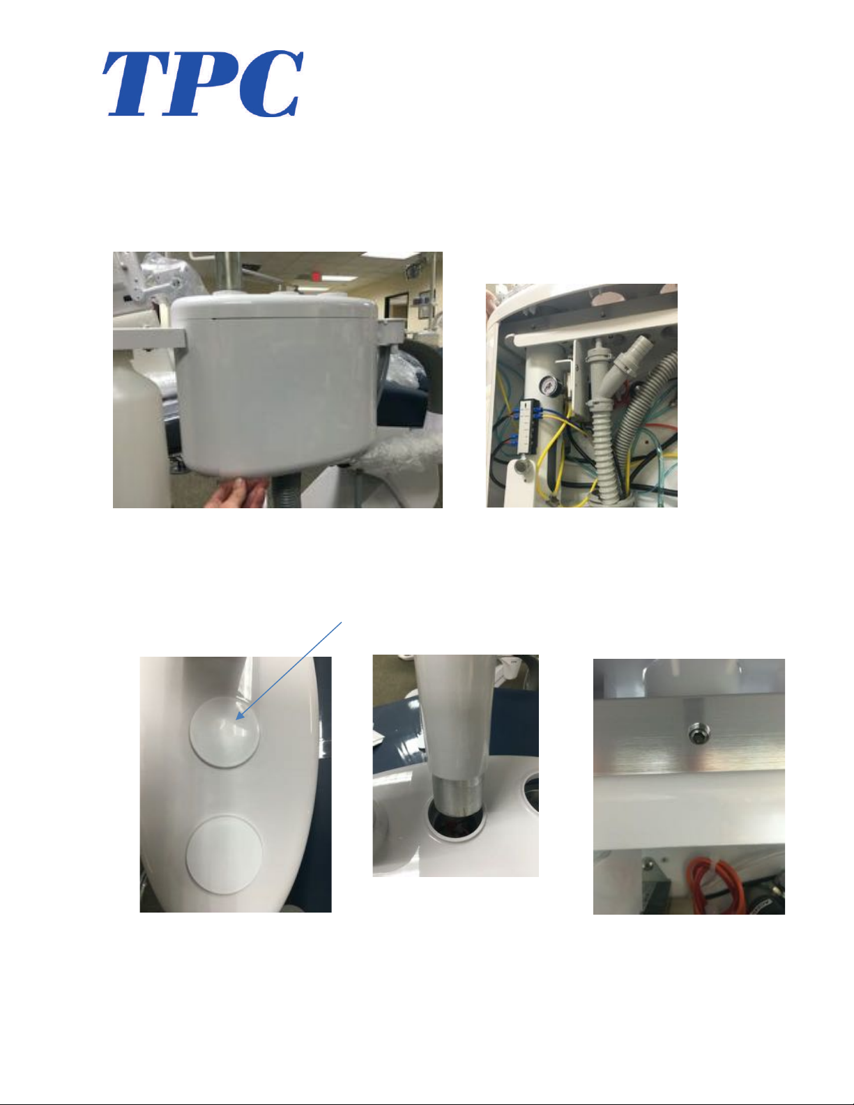
5. Remove the PMU side cover. To remove it, pull on the lower lip to detach its magnetic
connection. Place it out of the way so it does not get damaged. This side cover will
remain detached until the end of the installation.
6. Remove the plastic covers on the top of the PMU box Figure 6.1. Install the light post as
shown in the middle hole on the PMU side box Figure 6.2. Secure in place by tightening
the 4mm Allen set screw inside the PMU box Figure 6.3.
Figure 6.1
Figure 6.2
Figure 6.3
7
www.tpcdental.com
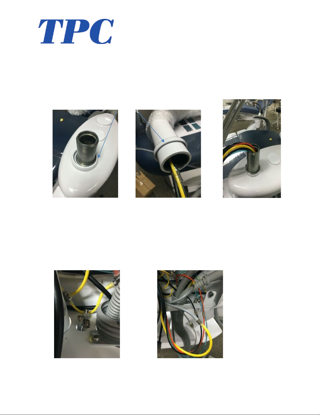
7. Remove the cosmetic rings from the side box figure 7.1. Place the cosmetic over the end
of the delivery unit flex arm Figure 7.2. Once in place, route all lines and feed them
through the bushing assembly shown in figure 7.3. Verify that the arm seats completely
down on the bushing assembly. Lower the cosmetic ring to cover the seam between the
arm and utility center cover.
8. Route the delivery system foot control and feed it through the bottom of the PMU figure
8.1. Make the following connections from your foot control to the tubing within the PMU
side box. Large yellow to Grey on foot control X2. Small grey on foot control to the clear
tubing to unit head for water relay connection. Figure 8.2.
Figure 7.1
Figure 7.2
Figure 7.3
Figure 8.1
Figure 8.2

8
www.tpcdental.com
9. Tubing connections in Post mount utility center.
• Orange from umbilical to Orange in flex arm. Signal Air return from master
switch.
• Black from umbilical to black in flex arm. Return signal air from master control.
• Small Grey from foot control to clear tubing in flex arm. Water relay signal air.
• Blue from umbilical to blue in flex arm. City water supply from J box to PMU
9
www.tpcdental.com
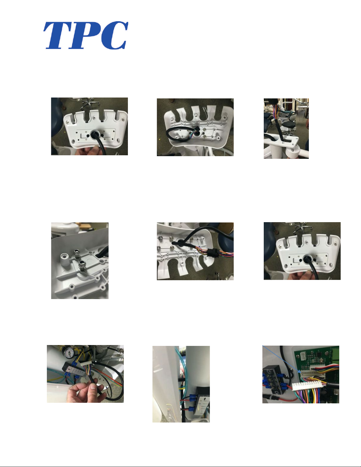
10. Installing assistance side touch pad. Remove the 5 screws that secure the covers together
Figure 10.1. Open the assistance holder and remove the 4 additional screws that attach
the bottom of the holder to the support frame in figure 10.2. Route the touchpad wire as
shown in figure Attach the touchpad bracket shown in figure 10.3.
11. Install the lower assistance cover over the 2 screws from the touchpad bracket. Install the
washers and nylon nuts for the touchpad screws shown in figure 11.1. Connect the Molex
connector from the touchpad to the wire harness shown in figure 11.2. Re-install the 5
screws to secure the top cover back onto assistance holder in figure 11.3.
12. Take the white 13 pin Molex connector that travels from the flex arm and route it to the
backside of the PMU to the PCB board Figure 12.1 / 12.2. Connect the harness to the
main PCB as shown in figure 12.3.
Figure 10.1
Figure 10.2
Figure 10.3
Figure 11.1
Figure 11.2
Figure 11.3
Figure 12.1
Figure 12.2
Figure 12.3
10
www.tpcdental.com
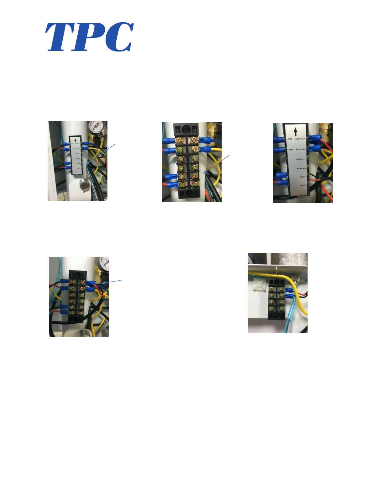
13. Install the operatory light onto light post. Ref operatory light installation manual for
specific installation instructions for your setup. Connect the power cable from the LED
light wire harness to the terminal bus bar in the side box. Figure 13.1shows the terminal
bus bar. Connect the power to the terminals that says light Figure 13.2 / 13.3. This bus
bar power is controlled via the touchpad. If you don’t require a touchpad controller
operatory light, you can connect the power to the ports on the bus bar labeled 24V. this
will provide constant 24V power to the LED operatory light.
14. Connect the low voltage wire from the unit flex arm to the terminal Bus bar in the side
box figure 14.1. This will provide 24VAC to the unit head termina bus bar if low voltage
applications are required. See red and black wires piggybacked on the 24V terminal
Figure 14.1. unit head terminal block show in figure 14.2
Figure 13.1
Figure 13.2
Figure 13.3
Figure 14.1
Figure 14.2

11
www.tpcdental.com
Optional Cuspidor Installation
15. To installing the optional cuspidor, remove the Cuspidor housing cover shown in figure
15.1. Loosen the locking screw shown in figure 15.2. Route tubing’s into the mounting
hub and slide the cuspidor into place Figure 15.3. Once the cuspidor is seated, tighten the
fastening screw in figure 15.2.
16. Insert the bowl into the cuspidor. Figure 16.1. Install cuspidor strainer, Figure 16.2.
Install the bowl rinse spout figure 16.3. Press the spout firmly into place.
Route the cuspidor power harness to the backside of the PMU. Figure 17.1. Connect to main
PCB shown in figure 17.2 Replace side cover Figure 17.3. You can de-activate the motion sensor
for the Cup Fill by not connecting the wire in figure 17.2. You then may activate “manually” the cup fill
by the button on both Touch Pad Controls.
Figure 15.1
Figure 15.2
Figure 15.3
Figure 16.1
Figure 16.2
Figure 16.3
Figure 17.1
Figure 17.2
Figure 17.3

12
www.tpcdental.com
Cuspidor Plumbing Connections
17. Connect the drain line and vent line from the cuspidor to the Y connector fittings in
Figure 18.1. You will need to cut the lines to length and then install it to the quick
connect fitting on the Y connector Figure 18.2. Both lines need to be free from kinks and
binding.
18. Connect the water lines from the cuspidor to the water solenoids mounted inside the post
mounted utility center Figure 19.1. The clear water line will connect to the solenoid on
the left. The blue line will connect to the solenoid on the right. Cut tubing’s to length
prior to installation.
19. To adjust the water flow for the cup fill and bowl rinse, turn the adjustment knob on the
water solenoid. Turn this knob clockwise to decrease the water flow. Turn the adjustment
counterclockwise to increase water flow. Figure 20.1.
Figure 18.1
Figure 18.2
Figure 18.3
Figure 19.1
Figure 20.1
13
www.tpcdental.com
Operation Instructions
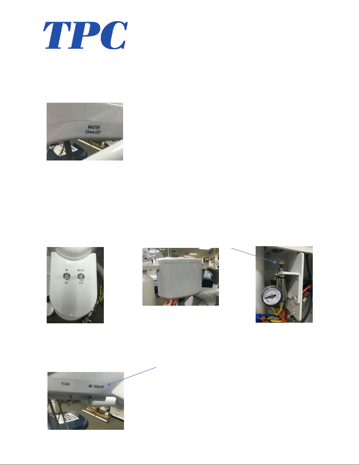
1. To turn the delivery unit “ON” switch the toggle on the right side of the delivery unit
head to the “ON” position. To turn the unit “OFF” toggle switch to the “OFF” position.
2. To select City water or bottle water, set the toggle selector switch to the correct position.
When setting the system to “bottle” you must also turn the ON / OFF switch to the “ON”
position. When changing the bottle, Turn the toggle to the “OFF” position to decompress
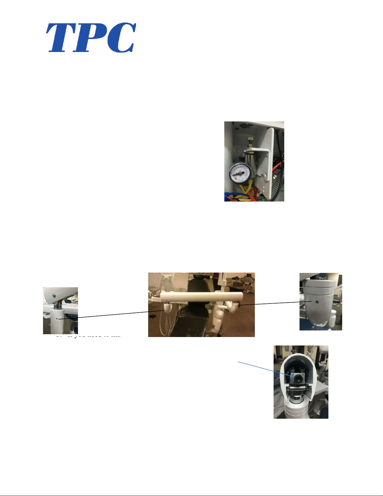
the bottle system prior to removal. If you need to increase the water pressure from the
bottle system, Remove the side cover of the post mounted utility center figure 2.2. Locate
the mini regulator shown in figure 2.3. Turn the adjustment knob clockwise to increase
the water pressure. Do-Not Exceed 35 PSI or damage to the bottle may occur.
3. Air Coolant adjustment. You can adjust the air coolant to the handpiece by adjusting the
air coolant knob on the right side of the delivery unit head figure 3.1. Turn the knob
clockwise to decrease, counterclockwise to increase.
Figure 1.1
Figure 2.1
Figure 2.3
Figure 2.2
Figure 3.1
14
www.tpcdental.com
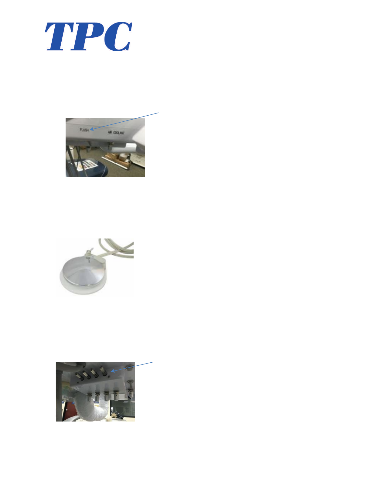
4. Flush Function. To perform a HP flush, Remove all three Handpieces from the delivery
unit handpiece holders. Place the HP tubing’s in a bucket or container to catch the water
that will be purged from the tubing’s. Use a suitable shock treatment and add to the water
bottle system. Toggle and hold the flush option on the side of the delivery unit head. This
will force the water to flush directly from the water bottle system through the water lines
in the unit head figure 4.1.
5. Variable speed wet dry foot control. Depress the disc on the foot control to supply air to
the unit head. If a handpiece is removed from its holder, that will be the active handpiece.
Using the toggle on the foot control will turn the water on / off to the unit’s handpiece
positions. Note: the blue dot on the shroud indicates the water is in the “ON” position.
6. D
7. D
8. D
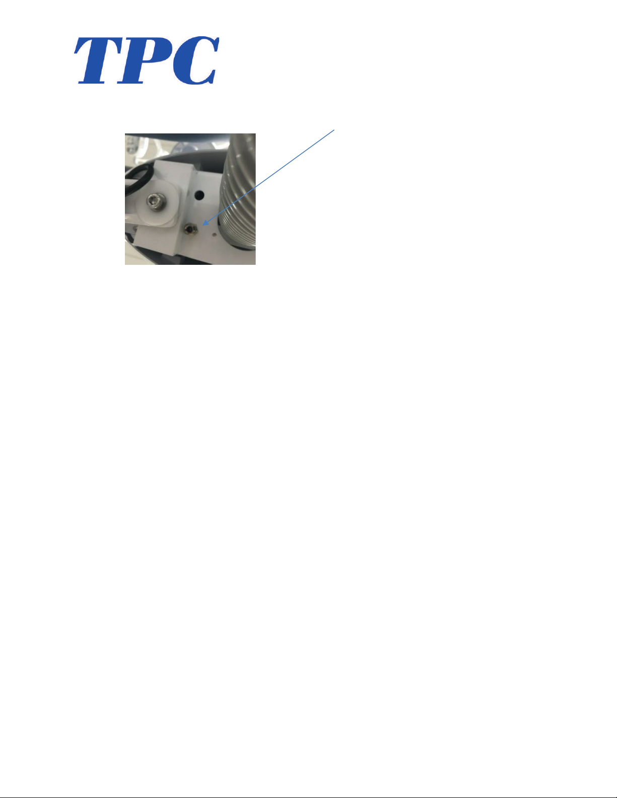
6. To adjust the handpiece pressure, use the adjustment knobs on the bottom of the unit.
Figure 6.1 Turning the adjustment knobs clockwise will decrease the pressure. Turning the
adjustment knobs counterclockwise will increase the pressure. To reference the HP pressure
to the HP position you can use the pressure gauge on the side of the delivery unit head Figure
6.2.
Figure 4.1
Figure 6.1
Insert Photo.
Figure 6.2
15
www.tpcdental.com
7. The mirage 2.0 delivery unit has a water quick disconnect. This is located under the post
mounted utility center. See figure 7.1 for location.

16
www.tpcdental.com
Junction Box Connections
20. Before making any connections in the junction box, be sure to clear the supply lines. If
there is any debris in the air line it will collect on the micron filter. Verify the line is
clear.
21. Once the line are verified and cleared, you may connect the master controls. The master
controls are similar looking. One is for the Air which is identified by the large yellow
tubing that exits the back end of the master control valve. The master control for the
water line is identified by the large blue line that exits the back of the master control
valve.
22. Once the connections are made you may open the angle stops or equivalent shut off
valve. Once the valve is open you may check the mater control gauges and verify that the
pressures are set accordingly. Air pressure should read approximately 80 PSI. Water
pressure should read 40 PSI.
23. Once air and water pressure are set, you may now make adjustments to the syringe blocks
if necessary. Also check your handpiece pressure and adjust accordingly.
17
www.tpcdental.com
Post mount utility center adjustments (PMU)
1. There are two main adjustments that can be made in the PMU.
• Assistant's side syringe block adjustments
Turning the screw counterclockwise will increase the air / water pressure.
Turning the screw clockwise will decrease the air / water pressure.
• Water bottle pressure adjustments
Loosen the lock nut, then turn the
knob counterclockwise to decrease
the air pressure. Turn the knob
clockwise to increase pressure.
DONT allow more then 40PSI of air
pressure to supply the bottle.
Tension Adjustments
2. In a situation that you need to add tension to the delivery unit flex arms please see the
following locations. NOTE: tension adjustments are only a temporary fix for drifting
arms. If your arms are drifting first verify the PMU is level. Check the light post to verify
its plum. If light post is not level make the proper adjustments by re-leveling the unit.
Tension spring adjustment
3. If you need to make adjustments to the tension spring in the flex arm, follow the
procedure below.
• Remove the flex arm cap cover.
• Use a 8 mm Allen wrench on the adjustment bolt.
• Turn clockwise to increase the tension
• Turn counterclockwise to decrease tension.
• Only make adjustments in half turn increments.
delivery head leveling and tilt adjustments
18
www.tpcdental.com
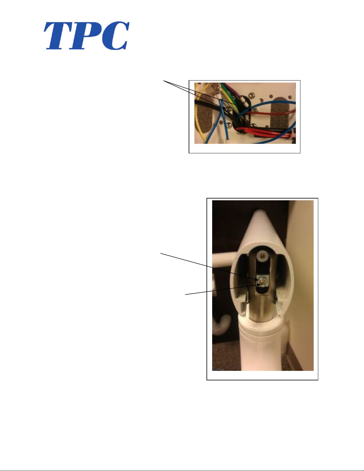
4. If you need to level the unit head or adjust the tilt use the following adjustments.
• Loosen the 4 Allen screws that attach the unit head to the short control arm. See
image. Once the screws are loose, use the two adjustment screws in the center on
each side to level the head.
• To adjust the unit head tilt, remove the flex arm end cap closest to the delivery
unit head. Loosen the stop nut, and using an Allen wrench turn the adjustment
screw clockwise to increase the tilt of the delivery unit head. Turn the adjustment
screw counter clockwise decrease the tilt.
*Stop Nut
*Adjustment Screw
Tubing and connections

19
www.tpcdental.com
Junction Box
1. Yellow 6 X 4 Air Supply line
2. Blue 6 X 4 Water Supply line
3. Grey Master Switch Supply
4. Yellow Master switch return
5. Purple Air brake supply
6. Red Spare
Post mount utility center (from umbilical to delivery unit arm)
1. Yellow 6 X 4 Supply line T to unit head.
2. Black 6 X 4 from output from foot control
3. Small Yellow / Small Yellow Master Switch return
4. Small Gray / Small Gray supply line to master switch
5. Small Purple / Small purple Supply to break
6. Small Blue / Small blue water supply line
7. Small burgundy Spare line
8. Small Green / Gray (wet dry toggle from F.C)
9. Small Black Spare (to flex arm)
10. Small Red Spare (to flex arm)
Junction box template
Table of contents
Other TPC Dental Equipment manuals


Popular Dental Equipment manuals by other brands

Cattani
Cattani MAXI SMART Operator's handbook

Belmont
Belmont PHOT-X II S 505 Service manual

Engler
Engler Vet II manual

MITSUI
MITSUI Kulzer Dynamix speed Instructions for use

Ivoclar Vivadent
Ivoclar Vivadent Programat CS6 Short instructions

Durr Dental
Durr Dental VistaScan Nano Easy Installation and operating instructions


Anthogyr
Anthogyr MICRO NITI 10608 Instructions for use

Woodpecker
Woodpecker WP-1L Repair manual

Schick Dental
Schick Dental QBasic operating instructions

mectron
mectron compact piezo P2K Use and maintenance manual

Aseptico
Aseptico ADU-25 Operation and maintenance instruction manual

GoodDrs
GoodDrs Dr's Finder user manual