5
To activate the water coolant, move the
wet/dry toggle switch on the foot pedal to
the right position. Move the toggle switch
to the left position to disable water coolant.
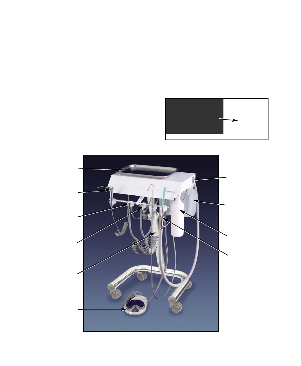
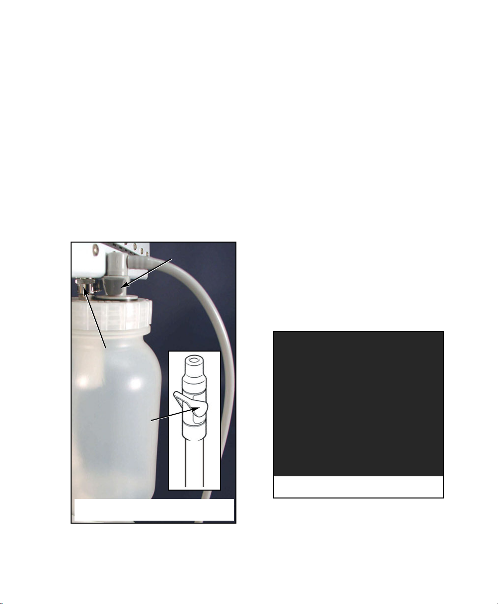
4. WATER SU LY TANK (Optional) - The
Aseptico ADU-25 may incorporate a self
contained pressurized water system (Fig.
9). This consists of a 1-liter HDPE tank
dispensing water through the 3-way syringe
and handpiece control. The water tank is
pressurized to a constant 35 pounds per
square-inch gauge (PSIG) during use.
Before removing the tank for refilling, it
must be depressurized by turning the tank
1/4 turn counterclockwise. The tank is
removed by unscrewing it from its mount
at the bottom right rear of the chassis.
After the tank is filled, screw it back onto
the mount. Cleaning and sanitization of
the tank is recommended between uses.
5. RESSURE GAUGE (Fig. 10) - The
pressure gauge on the right panel gives
you a visual indication of the handpiece
drive pressure.
6. WATER COOLANT FLOW CONTROL
(Fig. 10) - Adjusts the flow of water coolant
to the handpiece control.
7. FLUSH TOGGLE (Fig. 10) - The flush
toggle located on the right side of the
chassis allows you to quickly and
completely flush your handpieces, washing
away contaminants which may have
accumulated in the handpiece and tubing.
You should flush the handpieces for about
5 seconds after every patient, and about
20 seconds at the beginning of each day
to reduce overnight bacterial accumulation
which may have occurred.
To flush your handpieces, remove them
from their holder, directing the spray away
from you and into a basin, then flip the
flush toggle and hold the desired number
of seconds. Release the flush toggle.
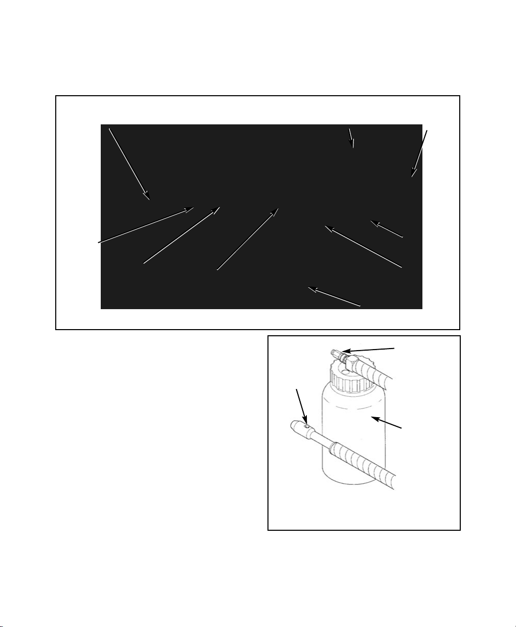
8. AA-21 HIGH VOLUME VACUUM
SYSTEM (Optional) - The AA-21 Steri-Vac
is an air powered, self contained oral
evacuator system. It is supplied with a
plastic waste container and a single high
velocity hose. (Fig. 11)
Remove the vacuum bottle and hose
assembly from packing and install into the
quick disconnect at the back of the
delivery head.
To operate, remove the vacuum hose from
holder and insert a standard oral evacuator
tip. Depress the on/off switch on the side
of the hose end for vacuum.
TU N WATE SUPPLY
TANK 1/4 TU N
COUNTE CLOCKWISE
TO ELEASE
P ESSU E BEFO E
UNSC EWING
Figure 9 - Removal of Optional ater Tank