Trikdis G16T User manual

www.trikdis.lt UAB Trikdis Draugystės str. 17, LT-51229 Kaunas, Lithuania +370 37 408 040 info@trikdis.lt
Cellular communicator G16T
Installation manual
October, 2018

www.trikdis.com 2 October, 2018
Cellular
communicator
G16T
Contents
DESCRIPTION ................................................................................................................................................................. 4
COMMUNICATOR MODEL TYPES ............................................................................................................................................4
SPECIFICATIONS .................................................................................................................................................................4
COMMUNICATOR ELEMENTS .................................................................................................................................................4
PURPOSE OF TERMINALS ......................................................................................................................................................5
LED INDICATION OF OPERATION ............................................................................................................................................6
STRUCTURAL SCHEMATIC WITH G16T USAGE ...........................................................................................................................6
QUICK CONFIGURATION WITH TRIKDISCONFIG SOFTWARE .......................................................................................... 7
SETTINGS FOR CONNECTION WITH PROTEGUS APP .....................................................................................................................8
SETTINGS FOR CONNECTION WITH ALARM RECEIVING CENTER .....................................................................................................9
INSTALLATION AND WIRING ....................................................................................................................................... 10
PHYSICAL INSTALLATION PROCESS ........................................................................................................................................10
WIRING COMMUNICATOR TO THE SECURITY CONTROL PANEL ....................................................................................................11
SCHEMATICS FOR CONNECTING TO PANEL KEYSWITCH ZONE ......................................................................................................12
SCHEMATICS FOR WIRING INPUTS ........................................................................................................................................12
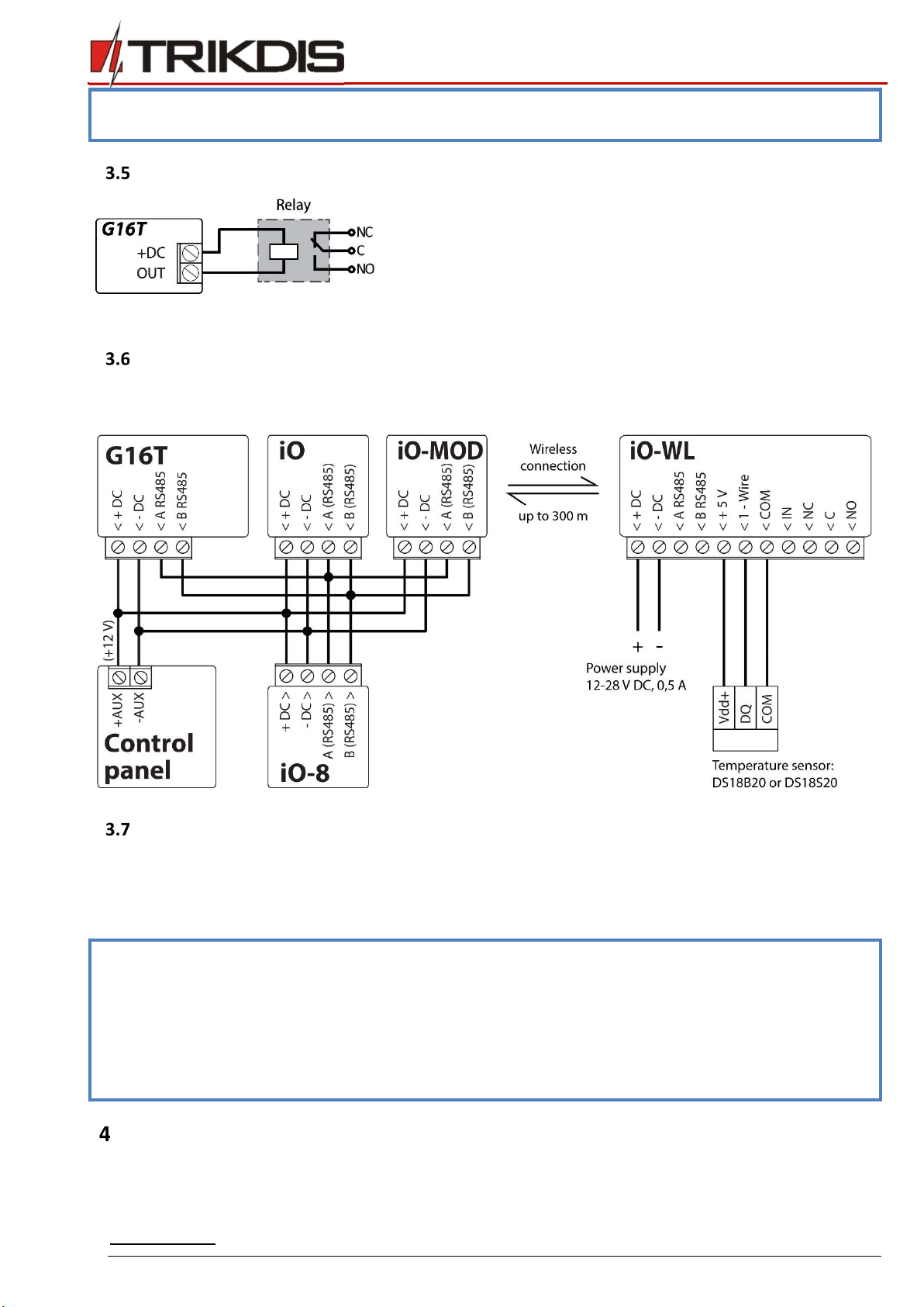
SCHEMATICS FOR WIRING A RELAY .......................................................................................................................................13
SCHEMATICS FOR CONNECTING IO SERIES EXPANSION MODULES ................................................................................................13
TURN ON THE COMMUNICATOR ..........................................................................................................................................13
PROGRAMMING THE CONTROL PANEL ....................................................................................................................... 13
PROGRAMMING HONEYWELL VISTA LANDLINE DIALER .............................................................................................................14
SPECIAL SETTINGS FOR HONEYWELL VISTA 48 PANEL ...............................................................................................................14
REMOTE CONTROL ...................................................................................................................................................... 14
ADDING THE SECURITY SYSTEM TO PROTEGUS APP ..................................................................................................................14
ADDITIONAL SETTINGS TO ARM/DISARM THE ALARM SYSTEM USING CONTROL PANEL’S KEYSWITCH ZONE ...........................................16
ARMING/DISARMING THE ALARM SYSTEM WITH PROTEGUS ......................................................................................................16
CONFIGURATION AND CONTROL WITH SMS MESSAGES ............................................................................................................17
TRIKDISCONFIG WINDOW DESCRIPTION ..................................................................................................................... 17
TRIKDISCONFIG STATUS BAR DESCRIPTION .............................................................................................................................17
“SYSTEM SETTINGS” WINDOW ............................................................................................................................................18
“ARC” REPORTING WINDOW ..............................................................................................................................................19
“USER REPORTING” WINDOW .............................................................................................................................................21
“SIM CARD” WINDOW ......................................................................................................................................................23
“RS485 MODULES” WINDOW ............................................................................................................................................23
“EVENT SUMMARY” WINDOW ............................................................................................................................................25
RESTORING FACTORY SETTINGS ...........................................................................................................................................26
REMOTE CONFIGURATION .......................................................................................................................................... 26
TEST COMMUNICATOR PERFORMANCE ...................................................................................................................... 26
MANUAL FIRMWARE UPDATE ..................................................................................................................................... 27

www.trikdis.com 3 October, 2018
Cellular
communicator
G16T
Safety requirements
The communicator should be installed and maintained by qualified personnel.
Prior to installation, please read this manual carefully in order to avoid mistakes that can lead to malfunction or even
damage to the equipment.
Disconnect the power supply before making any electrical connections.
Changes, modifications or repairs not authorized by the manufacturer shall void your rights under the warranty.
Please act according to your local rules and do not dispose of your unusable alarm system or its components with
other household waste.

www.trikdis.com 4 October, 2018
Cellular
communicator
G16T
Description
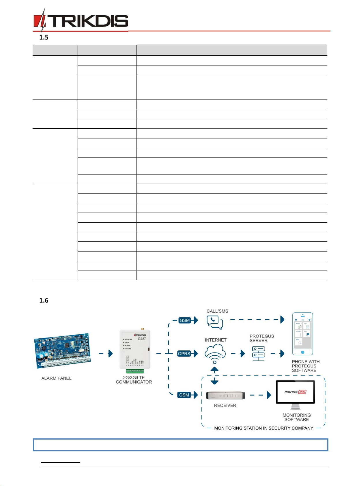
Cellular communicator G16T can be connected to any alarm panel that has a landline dialer and supports dialing in Contact ID
protocol with DTMF tones.
The communicator can transmit full event information to the security company’s monitoring station receiver.
The communicator works with the Protegus app. Users can control their alarm system remotely and receive notifications about
events. Protegus app works with all security alarm panels to which the communicator is connected to, regardless of
manufacturer. Communicator can transmit event notifications to the Central Monitoring Station and work with Protegus
simultaneously.
Cellular communicators G16T are certified to the highest EN50131 Grade 4 security rating.
Features
Connects to panel’s landline dialer:
Communicator can be connected to control panel’s
landline dialer with 2 or 4 wires.
When connected with 4 wires, the landline between
the panel and communicator will be monitored.
Sends events to monitoring station receiver:
Sends events to TRIKDIS software or hardware
receivers that work with any monitoring software.
Can send event messages to SIA DC-09 receivers.
Connection supervision by polling to IP receiver every
30 seconds (or by user defined period).
Backup channel, that will be used if connection with
the primary channel is lost.
Events can be reported to CMS with SMS messages.
SMS will be sent even if data connection stops
working in the mobile operator network.
With parallel communication channels events can be
sent to two receivers at same time.
When Protegus service is enabled, events are first
delivered to CMS, and only then are sent to app users.
Works with Protegus app:
“Push” and special sound notifications informing
about events.
Remote system Arm/Disarm.
Remote control of connected devices (lights, gates,
ventilation systems, heating, sprinklers, etc.).
Remote temperature monitoring (with iO or iO-WL
expanders).
Different user rights for administrator, installer and
user.
Users can also be informed about events with SMS
messages and phone calls.
Notifies users:
Users can be notified about events not only with
Protegus app, but also with SMS messages and a call.
Controllable outputs and inputs:
1 output, controlled via:
o Protegus app.
o SMS message.
2 inputs, selectable type: NC; NO; NC/EOL; NO/EOL;
NC/DEOL; NO/DEOL.
Add additional inputs and controllable outputs with
wired and wireless iO expanders.
Quick setup:
Settings can be saved to file and quickly written to
other communicators.
Two access levels for configuring the device for CMS
administrator and for installer.
Remote configuration and firmware updates.

www.trikdis.com 4 October, 2018
Cellular
communicator
G16T
Communicator model types
This manual applies to these G16T models:
G16T_321x – version 3, 2G modem, 1 SIM
G16T_331x – version 3, 3G modem, 1 SIM
G16T_341x – version 3, 4G modem, 1 SIM
G16T_3M1x – version 3, 4G modem CatM1, 1 SIM.
Specifications
Parameter Description
Connects to panel Landline dialer (TIP RING contacts)
Inputs 2 selectable type inputs, NC;NO; NC/EOL; NO/EOL; NC/DEOL; NO/DEOL
Expandable with iO series expanders
Output 1, OC type, up to 0,15 A, 30 V max
Expandable with iO series expanders
2G modem frequencies 850 / 900 / 1800 / 1900 MHz
3G modem frequencies 800 / 850 / 900 / 1900 / 2100 MHz
4G modem frequencies Depends on region
Power supply voltage 10-18 V DC
Current consumption 60-100 mA (on standby)
Up to 250 mA (while sending data)
Transmission protocols TRK, DC-09_2007, DC-09_2012
Message encryption AES 128
Changing settings With TrikdisConfig computer program remotely or locally via USB Mini-B port
Remotely with SMS messages
Operating environment Temperature from -10 °C to 50 °C, relative humidity - up to 80% at +20 °C
Communicator dimensions 92 x 65 x 26 mm
Weight 80 g
Communicator elements
1. Cellular antenna SMA connector
2. Light indicators
3. Frontal case opening slot
4. Terminal for external connections
5. USB Mini-B port for communicator
programming
6. SIM card slot
www.trikdis.lt UAB Trikdis Draugystės str. 17, LT-51229 Kaunas, Lithuania +370 37 408 040 info@trikdis.lt
Purpose of terminals
Terminal Description
+DC +10 V/+18 V power supply
-DC +10 V/+18 V power supply
TIP Terminal to connect with security control panel TIP terminal
RING Terminal to connect with security control panel RING terminal
T-1 / IN1 Terminal for monitoring the telephone line or an input terminal, selectable type: NC; NO; NC/EOL;
NO/EOL; NC/DEOL; NO/DEOL
R-1 / IN2 Terminal for monitoring the telephone line or an input terminal, selectable type: NC; NO; NC/EOL;
NO/EOL; NC/DEOL; NO/DEOL
COM Common terminal (negative)
OUT Output terminal (OC type), current up to 0,15 A
A 485 RS485 bus A contact
B 485 RS485 bus B contact
www.trikdis.com 6 October, 2018
Cellular
communicator
G16T
LED indication of operation
Indicator Light status Description
NETWORK Off No connection to cellular network.
Yellow blinking Connecting to cellular network.
Green solid with
yellow blinking
Communicator is connected to cellular network.
Sufficient cellular signal strength for 2G is level 5 (five yellow flashes) and for
3G, 4G network - level 3 (three yellow flashes).
DATA Off No unseen events.
Green solid Unsent event events are stored in buffer.
Green blinking (Configuration mode) Data is transferred to/from communicator.
POWER Off Power supply is off or disconnected.
Green solid Power supply is on with sufficient voltage.
Yellow solid Power supply voltage is not sufficient (≤11.5V).
Green solid and
yellow blinking
(Configuration mode) Communicator is ready for configuration.
Yellow solid (Configuration mode) No connection with computer.
TROUBLE OFF No operation problems.
1 red blink SIM card not found.
2 red blinks SIM card PIN code problem (incorrect PIN code).
3 red blinks Programming problem (No APN).
4 red blinks Registration to GSM network problem.
5 red blinks Registration to mobile data network problem.
6 red blinks No connection with the receiver.
7 red blinks Lost connection with control panel.
Red blinking (Configuration mode) Memory fault.
Red solid (Configuration mode) Firmware is corrupted.
Structural schematic with G16T usage
Note: Before you begin, make sure that you have the necessary:
www.trikdis.com 7 October, 2018
Cellular
communicator
G16T
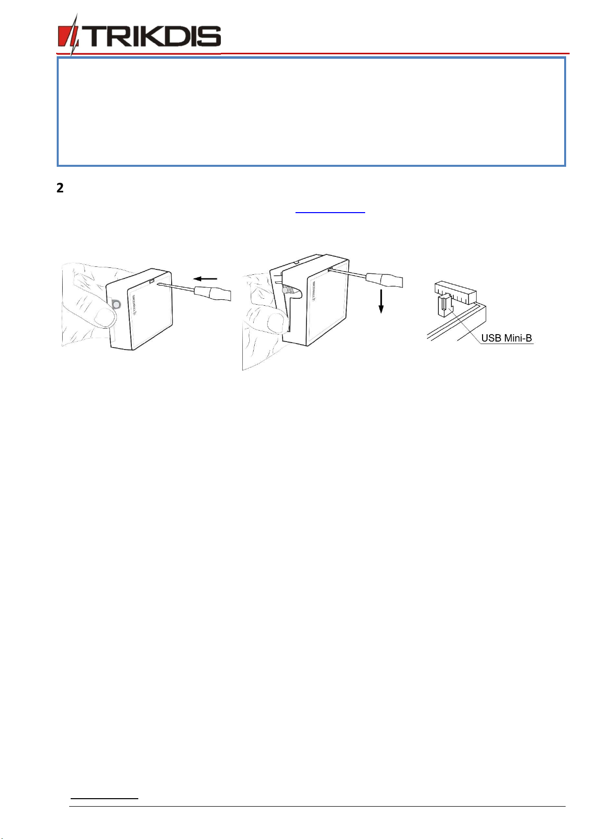
1) USB cable (Mini-B type) for configuration.
2) At least 4-wire cable for connecting communicator to control panel.
3) Flat-head 2.5mm screwdriver.
4) Sufficient gain cellular antenna if network coverage in the area is poor.
5) Activated Nano-SIM card (PIN code request can be turned off).
6) Particular security control panel`s installation manual.
Order the necessary components separately from your local distributor.
Quick configuration with TrikdisConfig software
1. Download configuration software TrikdisConfig from www.trikdis.com (type “TrikdisConfig” in the search field) and install
it.
2. Open the casing of the G16T with a flat-head screwdriver as shown below:
3. Using a USB Mini-B cable connect the G16T to the computer.
4. Run TrikdisConfig. The software will automatically recognize the connected communicator and will open a window for
configuration.
5. Click Read [F4] to read the communicator’s settings. If requested, enter the Administrator or Installer 6-digit code in the
pop-up window.
Below we describe what settings need to be set for the communicator to begin sending events to the Central Monitoring Station
and to allow the security control to be controlled with the Protegus app.

www.trikdis.com 8 October, 2018
Cellular
communicator
G16T
Settings for connection with Protegus app
In “User reporting window” “PROTEGUS Cloud” tab:
1) Select checkbox Enable connection to the PROTEGUS Cloud.
2) You can change the Cloud access Code for logging into Protegus if you want users to be asked to enter it when adding
the system to Protegus app (default password - 123456).
In “SIM card” window:
3) Enter SIM card PIN code.
4) Change APN name. APN can be found on the website of the SIM card operator (“internet” is universal and works in many
operator networks).
After finishing configuration, click the button Write [F5] and disconnect the USB cable.
Note: For more information about other G16T settings in TrikdisConfig, see chapter 6 TrikdisConfig window
description.
Important: Do not forget to turn on the landline dialer of the alarm panel and set it up correctly, so that the panel would
send the events. Alarm panel setup is described in chapter 4 Programming the control panel.

www.trikdis.com 9 October, 2018
Cellular
communicator
G16T
Settings for connection with Alarm Receiving Center
In “System settings” window:
1) Enter Object ID (account) number provided by the Central Monitoring Station (4 characters, 0-9, A-F).
In “ARC reporting” window settings for “Primary channel”:
2) Communication type - select the IP connection method (we do not recommend SMS as the primary channel).
3) Protocol - select the protocol type for your event messages: TRK (to TRIKDIS receivers), DC-09_2007 or DC-09_2012 (to
universal receivers).
4) TRK encryption key - enter the encryption key that is set in the receiver.
5) Domain or IP - enter the receiver’s Domain or IP address.
6) Port - enter receiver’s network port number.
7) TCP or UDP - choose event transmission protocol (TCP or UDP) in which events should be sent.
Note: If you want to set communication with ARC via SMS messages, you only need to set Encryption key and Phone
number. SMS messages can be received only by TRIKDIS receivers: IP/SMS receiver RL14, multichannel receiver
RM14 and SMS receiver GM14.
www.trikdis.com 10 October, 2018
Cellular
communicator
G16T
If you selected the DC-09 protocol, additionally enter object, line and receiver numbers in the Settings tab of
the ARC reporting window.
8) (Recommended) Configure Primary channel Backup settings.
9) (Recommended) Enter Backup SMS reporting number.
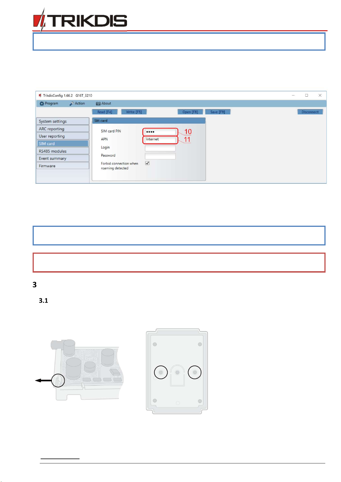
In “SIM card” window:
10) Enter SIM card PIN code.
11) Change the APN name. APN can be found on the website of the SIM card operator (“internet” is universal and works in
many operator networks).
After finishing configuration, click Write [F5] and disconnect the USB cable.
Note: For more information about other G16T settings in TrikdisConfig see chapter 6 TrikdisConfig window
description.
Important: Do not forget to turn on the landline dialer of the alarm panel and set it up correctly, so that the panel would
send the events. Alarm panel setup is described in chapter 4 Programming the control panel.
Installation and wiring
Physical installation process
1. Remove the top cover and pull out the contact terminal.
2. Remove the PCB board.
3. Fix the bottom part to the suitable place with screws.
4. Place the PCB board back into the case, insert contact terminal.
5. Screw cellular antenna on.

www.trikdis.com 11 October, 2018
Cellular
communicator
G16T
6. Insert nano-SIM card.
Note: Ensure that the SIM card is activated.
Ensure that mobile internet service (mobile data) is enabled if Protegus app or IP connection with ARC will be used.
To avoid entering the PIN code in TrikdisConfig, insert the SIM card into your mobile phone and turn off the PIN
request function.
7. Close the top cover.
Schematics for wiring the communicator to the security control panel
Following one of the schematics provided below, wire the communicator to the control panel.

www.trikdis.com 12 October, 2018
Cellular
communicator
G16T
Schematics for connecting to panel keyswitch zone
Follow these schematics if the control panel will be armed/disarmed with the G16T PGM output turning on/off the panel’s
keyswitch zone.
Note: The G16T communicator has one programmable output OUT, which can control one alarm system partition. In
the TrikdisConfig window “System settings” output OUT1 mode needs to be set to Remote control (default
setting).
Schematics for wiring inputs
The communicator has two input terminals (IN1, IN2) for connecting NO, NC, NO/EOL, NC/EOL, NO/DEOL, NC/DEOL type circuits.
Default input setting - NO. The input type can be changed in the TrikdisConfig window System settings -> Input IN1-IN2 type.
Connect the input according to the selected input type (NO, NC, NO/EOL, NC/EOL, NO/DEOL, NC/DEOL), as shown in the schemes
below:
www.trikdis.com 13 October, 2018
Cellular
communicator
G16T
Note: If more inputs or outputs need to be connected to the communicator, or if you want to connect a temperature
sensor, connect the TRIKDIS iO series wired or wireless output expander.
Schematics for wiring a relay
With relay contacts you can control (turn on/off) various electronic appliances.
Schematics for connecting iO series expansion modules
If more inputs or outputs need to be connected to the communicator, or if you want to connect a temperature sensor, connect
the TRIKDIS iO series wired or wireless output expander.
Turn on the communicator
To start the communicator, turn on the security control panel’s power supply. This LED indication on the G16T communicator
must show:
- “POWER” LED illuminates green when the power is on;
- “NETWORK” LED illuminates green and blinks yellow when the communicator is registered to the network.
Note: Sufficient strength of 2G cellular signal is level five (five “NETWORK” indicator flashes in yellow color). Sufficient
strength of 3G/4G signal is level three (three “NETWORK” indicator flashes in yellow color).
If you count less yellow “NETWORK” LED flashes, the network signal strength is insufficient. We recommend to
select a different place to install the communicator, or to use a more sensitive cellular antenna.
If you see a different LED indication, it indicates a certain malfunction. Diagnose it following the LED indication
table in chapter 1.5 LED indication of operation.
If the G16T indication does not illuminate at all, check the power supply and connections.
Programming the control panel
For the control panel to send events via the landline dialer, it must be turned on and properly set up. Following the panel’s
programming manual, configure the control panel’s landline dialer:

www.trikdis.com 14 October, 2018
Cellular
communicator
G16T
1. Turn on the panel’s PSTN landline dialer.
2. Enter the monitoring station receiver’s telephone number (you can use any number longer than 2 digits. The G16T will
pick up and answer when the panel calls to any phone number).
3. Choose DTMF mode.
4. Select Contact ID communication protocol.
5. Enter the panel’s 4 digit account number.
The control panel zone to which the G16T output OUT is connected should be set to keyswitch zone for arming/disarming the
control panel remotely.
Note: Keyswitch zone can be momentary (pulse) or level. By default, the G16T controllable output OUT is set to 3 second
pulse mode. You can change the impulse duration or change to level mode in Protegus settings. See chapter 5.2
Additional settings to arm/disarm the alarm system using control panel’s keyswitch zone.
Programming Honeywell Vista landline dialer
Using the control panel’s keypad enter these sections and set them as described:
*41 – enter monitoring station receiver telephone number;
*43 – enter control panel’s account number;
*47 – set the Tone dial to [1] and enter the number of dial attempts;
*48 – use default setting, *48 must be set to 77;
*49 – Split/Dual message. *49 must be set to 5;
*50 – delay for sending burglary alarm events (optional). Default value is [2,0]. With it the event message transmission
will be delayed for 30 seconds. If you want the message to be sent immediately, set [0,0].
Special settings for Honeywell Vista 48 panel
If you want to use G16T communicator with Honeywell Vista 48 panel, set the following sections as described:
Section Data Section Data Section Data
*41 1111 (receiver telephone number) *60 1 *69 1
*42 1111 *61 1 *70 1
*43 1234 (panel account number) *62 1 *71 1
*44 1234 *63 1 *72 1
*45 1111 *64 1 *73 1
*47 1 *65 1 *74 1
*48 7 *66 1 *75 1
*50 1 *67 1 *76 1
*59 0 *68 1
When all required settings are set, it is necessary to exit programming mode. Enter *99 in keypad.
Remote control
Adding the security system to Protegus app
With Protegus users will be able to control their alarm system remotely. They will see the status of the system and receive
notifications about system events.
1. Download and launch the Protegus application or use the browser version: www.protegus.eu/login.

www.trikdis.com 15 October, 2018
Cellular
communicator
G16T
2. Log in with your user name and password or register and create a new account.
Note: When adding the G16T to Protegus check if:
1. The inserted SIM card is activated and the PIN code is either entered or disabled;
2. Protegus cloud is enabled. See chapter 6.4 “User reporting” window;
3. Power supply is connected (“POWER” LED illuminates green);
4. Registered to the network (“NETWORK” LED illuminates green and flashes yellow);
3. Click Add new system and enter the G16T’s “IMEI/Unique ID” number. This number can be found on the device and the
packaging sticker. After entering press Next.
4. In the new window, click Areas in the side menu. In the next window specify how many alarm system areas are in the
system and press Next.
5. In the new window, identify what is the number for each of the specified areas in the security system and press Save.
www.trikdis.com 16 October, 2018
Cellular
communicator
G16T
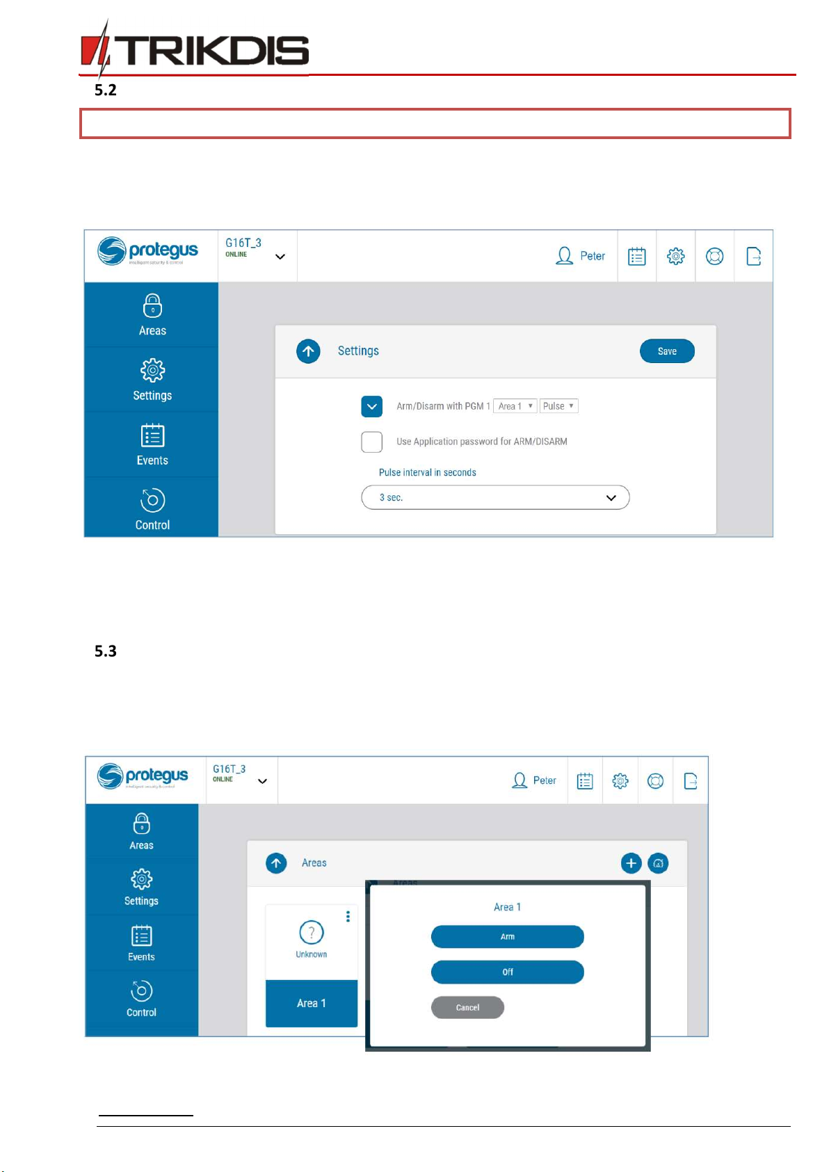
Additional settings to arm/disarm the alarm system using control panel’s keyswitch zone
Important: The control panel zone to which the G16T output OUT is connected to has to be set to keyswitch mode.
Follow the instructions below if the security control panel will be controlled with the G16T output OUT, turning on/off the control
panel keyswitch zone.
1. In the side menu press Settings and in the newly opened window press Settings. Select the box Arm/Disarm with PGM
and specify which area the output will control. One output OUT can control only one area.
2. Select Level or Pulse, depending on the type of control panel keyswitch zone. You can also change the duration of the
pulse interval if it is required for the connected control panel.
3. For additional security, you can select Use Application password for ARM/DISARM. Then after pressing the button to
arm/disarm the alarm system, a window for entering the app password will open.
Arming/disarming the alarm system with Protegus
1. To arm/disarm the alarm system, open the Protegus window Areas.
2. In the Areas window press the Area button. In the opened window select the action (to arm or to disarm the alarm
system).
3. If asked, enter the user code or Protegus password.

www.trikdis.com 17 October, 2018
Cellular
communicator
G16T
Configuration and control with SMS messages
You can remotely configure and control the communicator with SMS messages.
Message structure is: Password space Command space Data
For password use the Administrator code for INFO, RESET, OUTPUT1, CONNECT commands, and Installer code for INFO, RESET,
OUTPUT1 commands.
SMS command list
Command Data Description
INFO Request information about the device. Response will be: communicator type, IMEI
number, serial number and firmware version. E.g.: 123456 INFO
RESET Restart the device. E.g.: 123456 RESET
OUTPUT1 ON Turn on the OUTPUT1. E.g.: 123456 OUTPUT1 ON
OFF Turn off the OUTPUT1. E.g.: 123456 OUTPUT1 OFF
PULSE=tttt Turn on the output in impulse mode, for the specified time interval (sec).
“tttt” is the time duration of impulse in seconds, described in four digits.
E.g.: 123456 OUTPUT2 PULSE=0002
CONNECT Protegus=ON Enable access to Protegus service. E.g.: 123456 CONNECT PROTEGUS=ON
Protegus=OFF Disable access to Protegus service E.g.: 123456 CONNECT PROTEGUS=OFF
IP=0.0.0.0:8000 Set primary channel IP address and Port number.
E.g.: 123456 CONNECT IP=192.120.120.255:8000
ENC=123456 Set TRK encryption key. E.g.: 123456 CONNECT ENC=123456
APN=Internet Set APN name. E.g.: 123456 CONNECT APN=INTERNET
USER=user Set APN user. E.g.: 123456 CONNECT USER=User
PASS=password Set APN password. E.g.: 123456 CONNECT PASS=Password
CP= Disable the landline interface (1 - Disabled; 2 - Enabled).
E.g.: 123456 CONNECT CP=2
You can restrict the phone numbers from which the communicator will accept the commands. See chapter 6.4 “User reporting”
window, “Control by SMS” tab.
TrikdisConfig window description
TrikdisConfig status bar description
After connecting the G16T and clicking Read [F4], TrikdisConfig will provide information about the connected device in the status
bar:
Object Description
Unique ID Device IMEI number
Status Operating condition
Device Device type (G16T should be shown)
SN Device serial number

www.trikdis.com 18 October, 2018
Cellular
communicator
G16T
Object Description
BL Browser version
FW Device firmware version
HW Device hardware version
Status Connection to program type (via USB or remote)
Administrator Access level (shown after access code is approved)
After pressing Read [F4], the program will read and show the settings which are set in the G16T. Set the necessary settings
according to the TrikdisConfig window descriptions given below.
“System settings” window
“General” settings group
Object ID – if the events will be sent to the ARC (Alarm Receiving Center), enter the account number provided by the ARC
(4 characters hexadecimal number, 0-9, A-F).
Use security panel account ID – if the checkbox is selected, the communicator will send events with the account ID
entered in the panel instead of the value set in the Object ID field.
Wait acknowledgment from ARC – if the checkbox is selected, after sending each event the communicator will wait for
acknowledgment from the IP receiver indicating that it has successfully received the event message. If the communicator
will not receive the acknowledgement signal, it will not form the end-of-communication (kiss-off) signal. After not
receiving the kiss-off, the control panel landline dialer will repeatedly transmit the event message.
Panel type – enable/disable DTMF landline interface on the communicator.
Dial tone frequency – frequency in which the G16T communicates with the control panel landline dialer.
Line supervision – if this checkbox is selected, landline connection between the communicator and control panel will be
monitored. For the supervision to work, the control panel’s landline dialer needs to be connected with the G16T with 4
wires (see chapter 3.2 Schematics for wiring the communicator to the security control panel).
Input IN1-IN2 type – select the input type from the list (NO, NC, NO/EOL, NC/EOL, NO/DEOL, NC/DEOL).
Output OUT1 mode – select the output operation mode from the list.
Time synchronization – select which server to use for time synchronization.
“Access” settings group
Administrator code – allows you to access all configuration fields (default code - 123456).
Installer code – allows to change only those fields that are allowed by the administrator (default code - 654321).
www.trikdis.com 19 October, 2018
Cellular
communicator
G16T
Only an administrator can restore – if this box is selected, factory settings can be restored only by entering the
administrator code.
Allow installer to change – the administrator can specify which settings the installer can change.
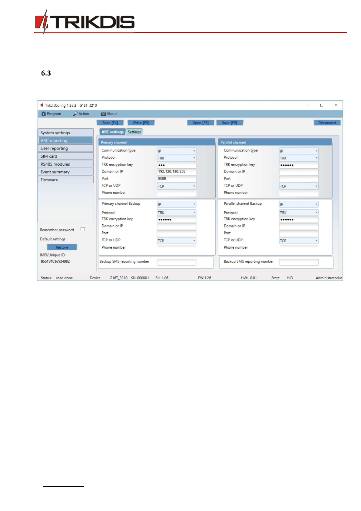
“ARC reporting” window
“ARC settings” tab
The communicator sends events to the monitoring station via cellular internet (IP) or with SMS messages.
Events can be sent through several communication channels. The primary and parallel communication channels can operate
simultaneously, this way the communicator can send events to two receivers at the same time. Backup channels can be assigned
for both primary and parallel channels, which will be used when the connection via the primary or parallel channel is interrupted.
Communication is encoded and password protected. A TRIKDIS receiver is required for receiving and sending event information
to the monitoring software:
For connection over IP – software receiver IPcom Windows/Linux, hardware IP/SMS receiver RL14 or multichannel
receiver RM14.
To receive SMS messages – hardware IP/SMS receiver RL14, multichannel receiver RM14 or SMS receiver GM14.
SMS communication is particularly useful as a backup channel, because it works even when there is no mobile internet
connection. We do not recommend SMS as a primary channel.
“Primary channel” settings group
Communication type – select which connection method to monitoring station receiver will be used (IP or SMS).
Protocol – select in which coding the events should be sent: TRK (to TRIKDIS receivers), SIA DC-09 (to receivers which
receive events encoded in SIA DC-09 format).
TRK encryption key – 6-digit message encryption key. The key written to the communicator must match the receiver’s
key.
Domain or IP – enter the domain or IP address of the receiver.
Port – enter the network port number of the receiver.
TCP or UDP – select in which protocol (TCP or UDP) the events should be sent.
Other manuals for G16T
2
Table of contents
Other Trikdis Cell Phone manuals

Trikdis
Trikdis E16T User manual

Trikdis
Trikdis E10T User manual

Trikdis
Trikdis E14 User manual

Trikdis
Trikdis G09 User manual

Trikdis
Trikdis G16 User manual

Trikdis
Trikdis Ethernet E16 User manual

Trikdis
Trikdis E10Tv2 User manual

Trikdis
Trikdis G10T User manual

Trikdis
Trikdis G16 User manual

Trikdis
Trikdis G10D User manual


