Trikdis Ethernet E16 User manual

www.trikdis.lt UAB Trikdis Draugystės str. 17, LT-51229 Kaunas, Lithuania +370 37 408 040 info@trikdis.lt
“Ethernet” communicator E16
Installation manual
February, 2020

www.trikdis.com 2 February, 2020
“Ethernet”
communicator
E
16
Contents
SAFETY REQUIREMENTS........................................................................................................................................................ 3
1 DESCRIPTION ............................................................................................................................................................. 4
1.1 List of compatible control panels ............................................................................................................................................ 5
1.2 Specifications .......................................................................................................................................................................... 5
1.3 Communicator elements ......................................................................................................................................................... 6
1.4 Purpose of terminals ............................................................................................................................................................... 6
1.5 LED indication of operation ..................................................................................................................................................... 6
1.6 Structural schematic with E16 usage ...................................................................................................................................... 7
2 QUICK CONFIGURATION WITH TRIKDISCONFIG SOFTWARE .................................................................................................... 7
2.1 Settings for connection with Protegus app ............................................................................................................................. 8
2.2 Settings for connection with Central Monitoring Station ........................................................................................................ 9
3 INSTALLATION AND WIRING ......................................................................................................................................... 10
3.1 Schematics for wiring the communicator to a security control panel ................................................................................... 10
3.2 Schematic for connecting to panel keyswitch zone ............................................................................................................... 11
3.3 Schematics for input connection ........................................................................................................................................... 12
3.4 Connect LAN cable ................................................................................................................................................................ 13
3.5 Schematics for wiring a relay ................................................................................................................................................ 13
3.6 Schematics for connecting iO series expansion modules ...................................................................................................... 13
3.7 Turn on the communicator ................................................................................................................................................... 13
4 PROGRAMMING THE CONTROL PANEL ............................................................................................................................ 14
5 REMOTE CONTROL .................................................................................................................................................... 16
5.1 Adding the security system to Protegus app ......................................................................................................................... 16
5.2 Additional settings to arm/disarm the system using the control panel’s keyswitch zone ..................................................... 16
5.3 Arming/disarming the alarm system with Protegus ............................................................................................................. 18
6 TRIKDISCONFIG WINDOW DESCRIPTION .......................................................................................................................... 19
6.1 TrikdisConfig status bar description ...................................................................................................................................... 19
6.2 “System settings” window .................................................................................................................................................... 20
6.3 “CMS reporting” window ...................................................................................................................................................... 21
6.4 “User reporting” window ...................................................................................................................................................... 23
6.5 “Ethernet settings” window .................................................................................................................................................. 23
6.6 “IN/OUT” windows................................................................................................................................................................ 24
6.7 “RS485 modules” window ..................................................................................................................................................... 24
6.8 “Event summary” window .................................................................................................................................................... 26
6.9 Restoring factory settings ..................................................................................................................................................... 27
7 REMOTE CONFIGURATION ........................................................................................................................................... 27
8 TEST COMMUNICATOR PERFORMANCE ........................................................................................................................... 27
9 FIRMWARE UPDATE ................................................................................................................................................... 28
10 ANNEX ................................................................................................................................................................... 29

www.trikdis.com 3 February, 2020
“Ethernet”
communicator
E
16
Safety requirements
The communicator should be installed and maintained by qualified personnel.
Prior to installation, please read this manual carefully in order to avoid mistakes that can lead to malfunction or even damage
to the equipment.
Disconnect the power supply before making any electrical connections.
Changes, modifications or repairs not authorized by the manufacturer shall void your rights under the warranty.
Please act according to your local rules and do not dispose of your unusable alarm system or its components with
other household waste.

www.trikdis.com 4 February, 2020
“Ethernet”
communicator
E
16
1 Description
“Ethernet” communicator E16 directly connects to supported DSC, Paradox, UTC Interlogix (CADDX), Innerrange, Texecom,
Honeywell, Crow and Pyronix alarm panels.
Communicator transmits full event information to the Central Monitoring Station.
Communicator also works with Protegus application. With Protegus users can control their alarm system remotely and get
notifications about security system events. Protegus app is compatible with all security alarm panels from various manufacturers
that are supported by the E16 communicator. Communicator can transmit event notifications to the Central Monitoring Station
and work with Protegus simultaneously.
For panels from other manufacturers use the E16T communicator.
Features
Sends events to monitoring station receiver:
Sends events to TRIKDIS software or hardware receivers that work with
any monitoring software.
Can send event messages to SIA DC-09 receivers.
Can send event messages to SUR-GARD receivers. The annex has a
table for converting Contact ID codes to SIA codes.
Connection supervision by polling to IP receiver every 30 seconds (or
by user defined period).
Backup channel, that will be used if connection with the primary
channel is lost.
With parallel communication channels events can be sent to two
receivers at same time.
When Protegus service is enabled, events are first delivered to CMS,
and only then are sent to app users.
Works with Protegus app:
“Push” and special sound notifications informing about events.
Remote system Arm/Disarm.
Remote control of connected devices (lights, gates, ventilation
systems, heating, sprinklers, etc.).
Remote temperature monitoring (with iO or iO-WL expanders).
Different user rights for administrator and installer.
Notifies users:
Users can be notified about events with Protegus app.
Controllable outputs and inputs:
3 double I/O terminals that can be set either as input (IN) or controllable output (OUT) terminals.
Outputs controlled by the Protegus app.
Add additional inputs and controllable outputs with wired and wireless iO expanders.
Quick setup:
Settings can be saved to file and quickly written to other communicators.
Two access levels for configuring the device for CMS administrator and for installer.
Remote configuration and firmware updates.

www.trikdis.com 5 February, 2020
“Ethernet”
communicator
E
16
1.1 List of compatible control panels
Underlined - Control panels directly controlled by E16.
*Connect control panels from other manufacturers to the E16T communicator.
1.2 Specifications
Parameter Description
Dual purpose terminals
[IN/OUT]
3, can be set as either NC; NO; NC/EOL; NO/EOL; NC/DEOL; NO/DEOL (2,2 kΩ) type inputs
or open collector (OC) type outputs with current up to 0,15 A, 30 VDC max.
Expandable with iO series expanders.
Power supply voltage 10-18 V DC
Current consumption 100 mA (on standby)
Up to 250 mA (while sending data)
Ethernet connection IEEE802.3, 10 Base-T, RJ45 socket
Transmission protocols TRK, DC-09_2007, DC-09_2012, TL150
Memory Up to 60 messages
Changing settings With TrikdisConfig computer program remotely or locally via USB Mini-B port
Operating environment Temperature from -10 °C to 50 °C, relative humidity - up to 80% at +20 °C
Communicator dimensions 88 x 65 x 26 mm
Weight 80 g
Manufacturer Model
DSC® PC585, PC1404, PC1565, PC1616, PC1832, PC1864, PC5020
PARADOX® SPECTRA SP4000, SP5500, SP6000, SP7000, SP65
MAGELLAN MG5000, MG5050, MG5050E
DIGIPLEX EVO48, EVO192, EVOHD, NE96, EVO96
SPECTRA 1727, 1728, 1738
ESPRIT E55, 728ULT, 738ULT
UTC Interlogix® NetworX (Caddx) NX-4v2, NX-6v2, NX-8v2, NX-8E
Texecom® Premier 24, 48, 88, 168
Premier Elite 12, 24, 48, 64, 88, 168
Pyronix® MATRIX 424, MATRIX 832, MATRIX 832+, MATRIX 6, MATRIX 816
Innerrange® Inception
Honeywell® Ademco Vista-5, Ademco Vista-20, Ademco Vista-48
Crow® Runner 4/8, Runner 8/16

www.trikdis.com 6 February, 2020
“Ethernet”
communicator
E
16
1.3 Communicator elements
1. Light indicators.
2. Frontal case opening slot.
3. Terminal for external
connections.
4. USB Mini-B port for
communicator programming.
5. Ethernet connection RJ45
socket.
1.4 Purpose of terminals
Terminal Description
+DC +10 V/+18 V power supply
-DC +10 V/+18 V power supply
CLK Serial bus terminals for direct connection to control panel
DATA
I/O 1 1st input/output terminal
I/O 2 2nd input/output terminal
I/O 3 3rd input/output terminal
COM Common (negative) terminal
A RS485 RS485 bus A contact
B RS485 RS485 bus B contact
1.5 LED indication of operation
Indicator Light status Description
NETWORK Off No connection to a computer network
Green solid Communicator is connected to a computer network
DATA Off No unsent events
Green solid Unsent events are stored in buffer
Green blinking (Configuration mode) Data is being transferred to/from communicator
POWER Off Power supply is off or disconnected
Green solid Power supply is on with sufficient voltage
Yellow solid Power supply voltage is insufficient (≤11.5V)
Green solid and
yellow blinking
(Configuration mode) Communicator is ready for configuration
www.trikdis.com 7 February, 2020
“Ethernet”
communicator
E
16
Indicator Light status Description
Yellow solid (Configuration mode) No connection with computer
TROUBLE OFF No operation problems
1 red blink Connection error at the "physical" level (PHY Link status error)
2 red blinks DHCP error
3 red blinks DNS error
6 red blinks No connection with the receiver
7 red blinks Lost connection with control panel
Red blinking (Configuration mode) Memory fault
Red solid (Configuration mode) Firmware is corrupted
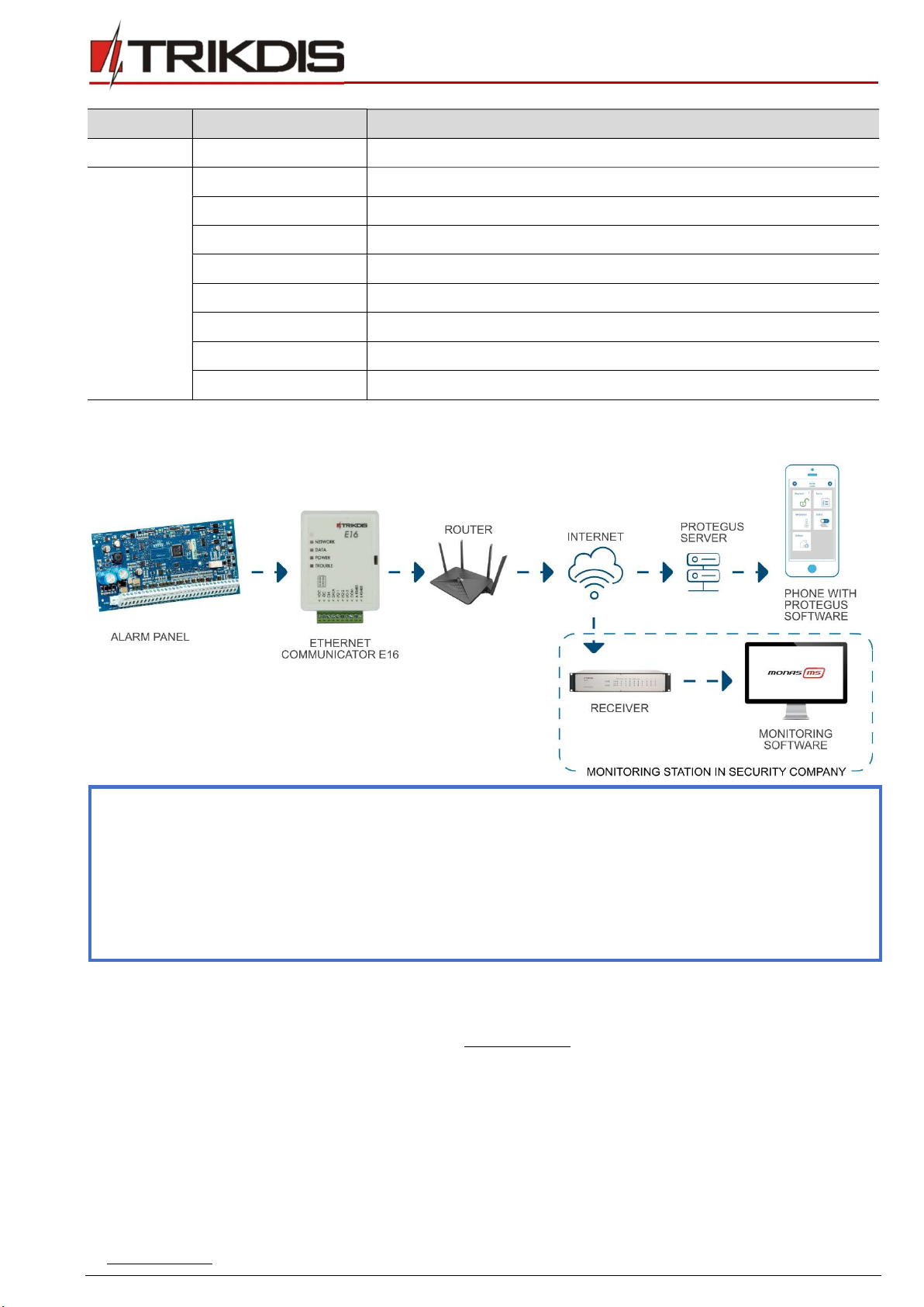
1.6 Structural schematic with E16 usage
Note: Before you begin, make sure that you have the necessary:
1. USB cable (Mini-B type) for configuration.
2. At least 4-wire cable for connecting communicator to control panel.
3. CRP2 cable for connecting to Paradox panel`s serial port.
4. Flat-head 2,5 mm screwdriver.
5. Particular security control panel`s installation manual.
Order the necessary components separately from your local distributor.
2 Quick configuration with TrikdisConfig software
1. Download TrikdisConfig configuration software from www.trikdis.com (type “TrikdisConfig” in the search field) and
install it.
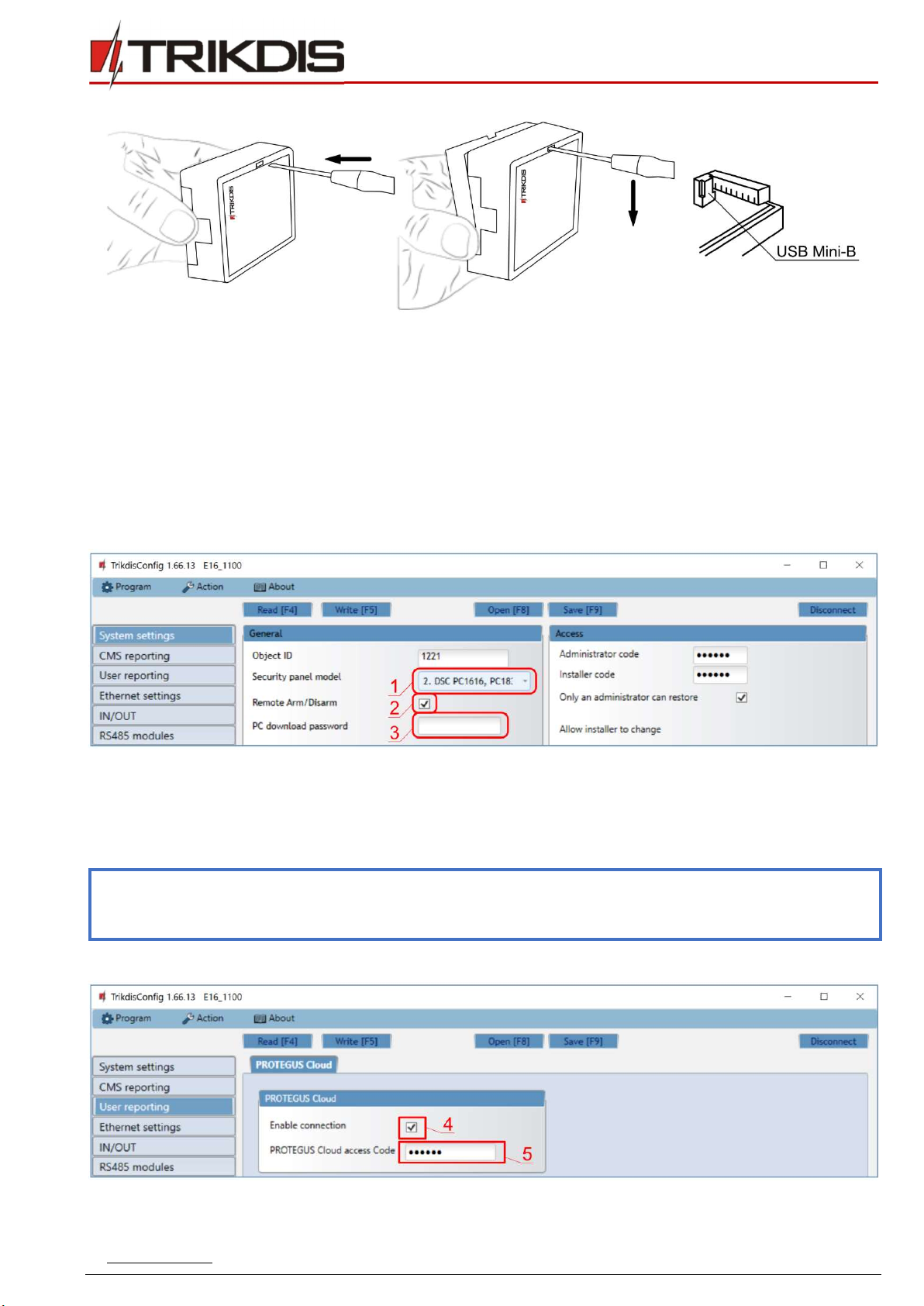
2. Open the casing of the E16 with a flat-head screwdriver as shown below:
www.trikdis.com 8 February, 2020
“Ethernet”
communicator
E
16
3. Using a USB Mini-B cable connect the E16 to the computer.
4. Run TrikdisConfig. The software will automatically recognize the connected communicator and will open a window for
configuration.
5. Click Read [F4] to read the communicator’s settings. If requested, enter the Administrator or Installer 6-digit code in the
pop-up window.
Below we describe what settings need to be set for the communicator to begin sending events to the CMS (central monitoring
station) and to allow the security system to be controlled with the Protegus app.
2.1 Settings for connection with Protegus app
In “System settings” window:
1) Select Security panel model that will be connected to the communicator.
2) Select Remote Arm/Disarm if you want users to be able to control the panel in Protegus app with their keypad code.
This setting is only shown for directly controlled panels.
3) For the direct control of Paradox and Texecom panels enter PC download password. It must match the password that is
entered in the control panel.
Note: For the direct panel control to work, you will need to change the panel settings. How to do this is described in
chapter 4 “Programming the control panel”. In this section you will find information on how to change the PC
download/UDL password.
In “User reporting” window, “PROTEGUS Cloud” tab:
4) Tick the checkbox Enable connection to the Protegus Cloud.
www.trikdis.com 9 February, 2020
“Ethernet”
communicator
E
16
5) Change the Protegus Cloud access Code for logging in to Protegus if you want users to be asked to enter it when adding
the system to Protegus app (default password – 123456).
After finishing configuration, click the button Write [F5] and disconnect the USB cable.
Note: For more information about other E16 settings in TrikdisConfig, see chapter 6 “TrikdisConfig window
description”.
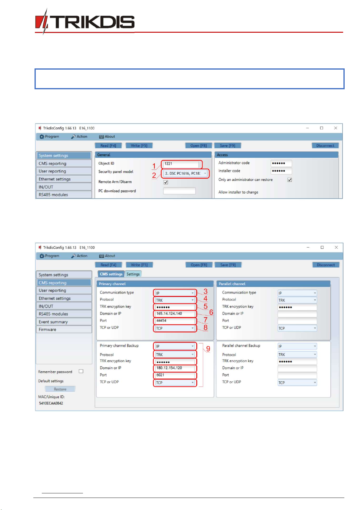
2.2 Settings for connection with Central Monitoring Station
In “System settings” window:
1) Enter Object ID (account) number provided by the Central Monitoring Station (4 characters, 0-9, A-F. Do not use FFFE,
FFFF Object ID.).
2) Select Security panel model that will be connected to the communicator.
In “CMS reporting” window settings for “Primary channel”:
3) Communication type - select the IP connection method.
4) Protocol - select the protocol type for event messages: TRK (to TRIKDIS receivers); DC-09_2007 or DC-09_2012 (to
universal receivers); TL150 (to SUR-GARD receivers).
5) TRK encryption key - enter the encryption key that is set in the receiver.
6) Domain or IP - enter the receiver’s Domain or IP address.
7) Port - enter receiver’s network port number.
www.trikdis.com 10 February, 2020
“Ethernet”
communicator
E
16
8) TCP or UDP - choose event transmission protocol (TCP or UDP) in which events should be sent.
Note: If you selected the DC-09 protocol, additionally enter object, line and receiver numbers in the Settings tab of
the CMS reporting window.
9) (Recommended) Configure Primary channel Backup settings.
10) (Recommended) Configure Parallel Channel and its Parallel Channel Backup settings.
After finishing configuration, click Write [F5] and disconnect the USB cable.
Note: For more information about other E16 settings in TrikdisConfig, see chapter 6 “TrikdisConfig window
description”.
3 Installation and wiring
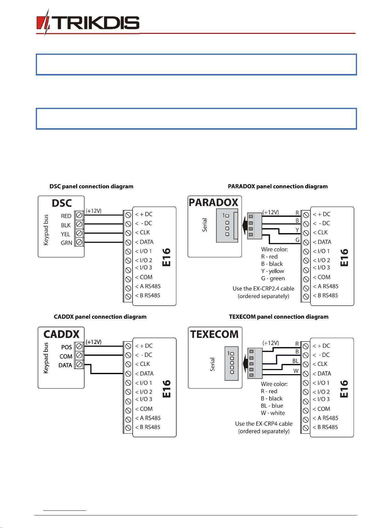
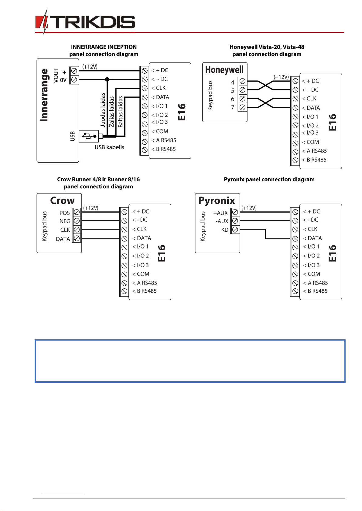
3.1 Schematics for wiring the communicator to a security control panel
Following one of the schematics provided below, connect communicator to the control panel.
www.trikdis.com 11 February, 2020
“Ethernet”
communicator
E
16
3.2 Schematic for connecting to panel keyswitch zone
Follow this schematic if the control panel will be armed/disarmed with a E16 PGM output turning on/off the panel’s keyswitch
zone.
Note: E16 communicator has 3 universal input / output terminals that can be set to the OUT (PGM) operating mode.
The outputs (OUT) can control three areas of the security system. If you want to control the system in this way,
in TrikdisConfig, in the "System settings" window, uncheck Remote Arm/Disarm. The Protegus apps must be
configured with the settings described in chapter 5.2 “Additional settings to arm/disarm the system using the
control panel’s keyswitch zone”.

www.trikdis.com 12 February, 2020
“Ethernet”
communicator
E
16
3.3 Schematics for input connection
The communicator has 3 universal input / output terminals that can be set to input IN mode. NC, NO, NO / EOL, NC / EOL, NO /
DEOL, NC / DEOL circuits can be connected to the input terminal. Default input setting – NO. The input type can be changed in
the TrikdisConfig window IN/OUT -> Type.
Connect the input according to the selected input type (NO, NC, NC/EOL, NO/EOL, NO/DEOL, NC/DEOL), as shown in the schemes
below:
Note: If more inputs or outputs need to be connected to the communicator, connect the TRIKDIS iO series wired or
wireless output expander. Connection method is described in the iO manual and chapter 3.6 “Schematics for
connecting iO series expansion modules”.

www.trikdis.com 13 February, 2020
“Ethernet”
communicator
E
16
3.4 Connect LAN cable
3.5 Schematics for wiring a relay
With relay contacts you can control (turn on/off) various electronic
appliances. The I/O terminal of the communicator must be set to an
output (OUT) mode.
3.6 Schematics for connecting iO series expansion modules
If more inputs or outputs need to be connected to the communicator, or if you want to connect a temperature sensor, connect
the TRIKDIS iO series wired or wireless output expander. Configuration of expander modules connected to the E16 is described
in chapter 6.6 ““RS485 modules” window”.
3.7 Turn on the communicator
To start the communicator, turn on the security control panel’s power supply. This LED indication on the E16 communicator
must show:
“POWER” LED illuminates green when the power is on;
“NETWORK” LED illuminates green, when the communicator is connected to the network.

www.trikdis.com 14 February, 2020
“Ethernet”
communicator
E
16
Note: If you see a different LED indication, it indicates a certain malfunction. Diagnose it by following the LED
indication table in chapter 1.5 “LED indication of operation”.
If the E16 indication does not illuminate at all, check the power supply and connections.
4 Programming the control panel
Below it is described how to program the security control panel so that the E16 communicator could read events from the panel
and control it remotely.
To enable remote control of the security panel, make sure that the checkbox Remote Arm/Disarm is selected in the TrikdisConfig
window “System settings”.
DSC
DSC panels do not need to be programmed.
PARADOX
Paradox control panels need to be programmed only for direct control with Protegus. You do not need to program Paradox
panels for reading events.
For remote control of Paradox panels, you need to set up a PC download password. This password must match the password
which was set in the TrikdisConfig window “System settings”, when the checkbox next to Remote Arm/Disarm was selected.
To set this password, with the keyboard connected to the security control panel:
For MAGELLAN, SPECTRA series: go to cell 911 and enter 4-digit PC download password.
For DIGIPLEX EVO series: go to cell 3012 and enter 4-digit PC download password.
TEXECOM
Texecom control panels need to be programmed for both reading events and remote control.
You need to set the Texecom panel’s UDL passcode. This password must match the password which was set in the TrikdisConfig
window “System settings”, when the box next to Remote Arm/Disarm was selected.
The security control panel can be programmed with Texecom software - Wintex. Enter UDL passcode (4-digit code) in the
Communication Options window, Options tab.
Also, you can program with a keypad connected to the security control panel:
1. Enter the 4-digit installer’s code and press the [Menu] button to enter the programming menu.
2. Press the [9] key immediately afterwards.
3. Press [7][6], and then [2]. Enter the 4-digit UDL passcode (UDL passcode must match the E16 communicator’s PC login
password).
4. Press [Yes] and leave the programming mode by pressing [Menu].
UTC INTERLOGIX (CADDX)
Security control panel version must be V2 or higher With the keyboard connected to the security control panel:
1. Press [*][8] and enter the installer’s code (default - 9713).
2. Enter the device number assigned to the connected communicator (default - 0).
3. Set the settings below for each row. In sequence, enter the position, segment number and the required setting. Clicking
[*] (asterisk) will return you to the local input field.
Position Segment Setting
23 3 12345678
37 (not necessary) 3 12345678
4 1234567*
90 3 12345678
93 3 12345678
www.trikdis.com 15 February, 2020
“Ethernet”
communicator
E
16
Position Segment Setting
96 3 12345678
99 3 12345678
102 3 12345678
105 3 12345678
108 3 12345678
After having programmed all the fields listed, press [Exit] twice to exit the programming mode.
INNERRANGE
Innerrange Inception security control panel version must be 2.3.0.3507-r0 or higher.
The control panel must be connected to the internet. Connect to Innerrange Inception by entering:
https://skytunnel.com.au/inception/SERIALNUMBER, where SERIALNUMBER is the number of the controller that you can find
on the panel’s enclosure.
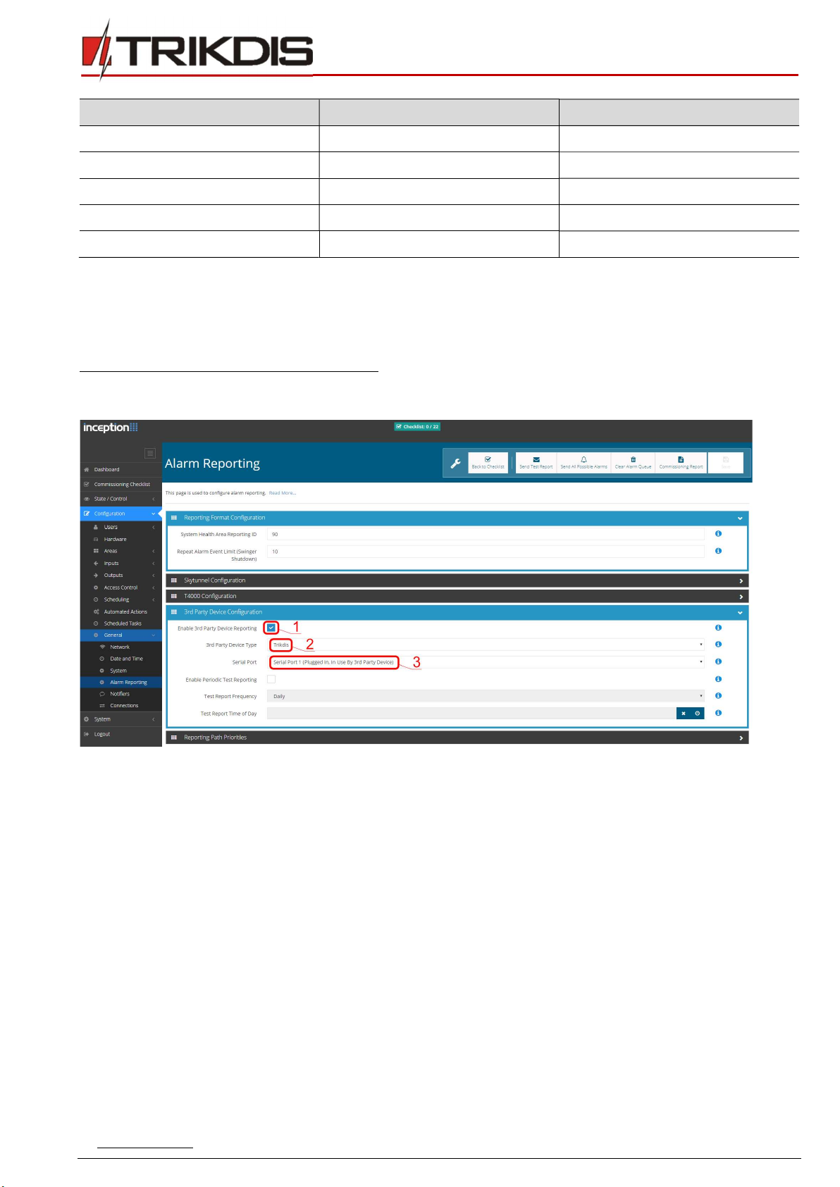
Open Configuration > General > Alarm Reporting. In the 3rd Party Device Configuration settings group you need to enter:
1. Enable 3rd Party Device Reporting - select this checkbox.
2. 3rd Party Device Type - set “Trikdis”.
3. Serial port - set “Serial Port 1 (Plugged In, In Use By 3rd Party Device)”.
4. Save settings and exit the application.
Honeywell Ademco Vista
Follow these steps for Honeywell Ademco Vista-20 and Honeywell Ademco Vista-48 panels. The panel’s firmware version
must be V5.3 or higher. With a keypad that is connected to the panel:
1. Enter the programming mode. Enter the installer code 4][1][1][2] and after that [8][0][0] . Alternatively, turn on the
panel‘s power supply. In 50 seconds after the power supply is turned on, press the buttons [*] and [#] at the same time
(this method can be used when programming mode was exited by pressing in keypad [*][9][8] ).
2. Turn on the sending of Contact ID events via LRR. Press [*][2][9][1][#] in keypad.
3. When using the „Remote Arm/Disarm“ function, allow to use the 2nd AUI address. In keypad press [*][1][8][9][1][1][#] .
Exit the programming mode. In keypad press [*][9][9]
Crow
There is no need to program Crow Runner 4/8 and Runner 8/16 panels.
www.trikdis.com 16 February, 2020
“Ethernet”
communicator
E
16
5 Remote control
5.1 Adding the security system to Protegus app
With Protegus users will be able to control their alarm system remotely. They will see the status of the system and receive
notifications about system events.
1) Download and launch the Protegus application or use the browser version: www.protegus.eu/login.
2) Log in with your user name and password or register and create new account.
Important: When adding the E16 to Protegus check if:
1. Protegus cloud is enabled. See chapter 6.4 ““User reporting” windows”;
2. Power supply is connected (“POWER” LED illuminates green);
3. Registered to the network (“NETWORK” LED illuminates green).
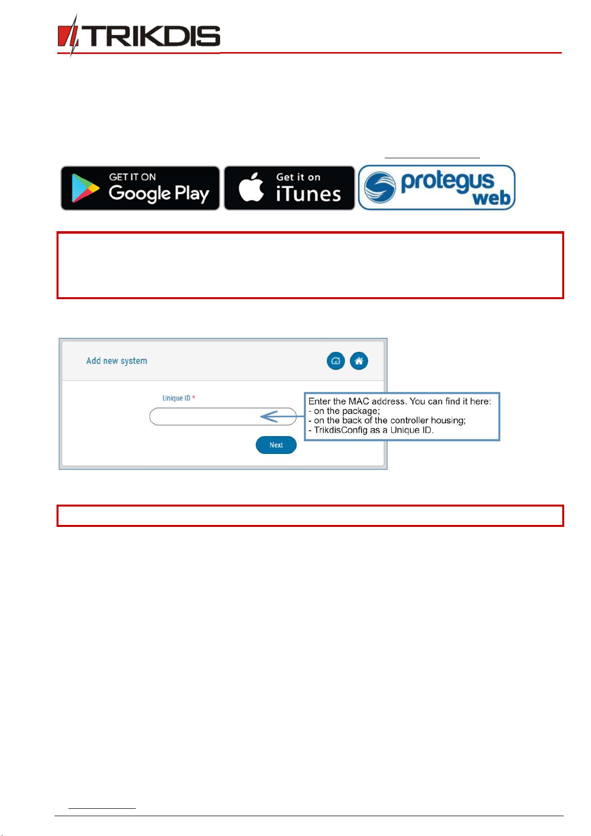
3) Click Add new system and enter the E16’s “MAC” number. This number can be found on the device and the packaging
sticker. After entering click Next.
5.2 Additional settings to arm/disarm the system using the control panel’s keyswitch zone
Important: The control panel zone to which the E16 output OUT is connected to has to be set to keyswitch mode.
Follow the instructions below if the security control panel will be controlled with a E16 PGM output, turning on/off the control
panel keyswitch zone.
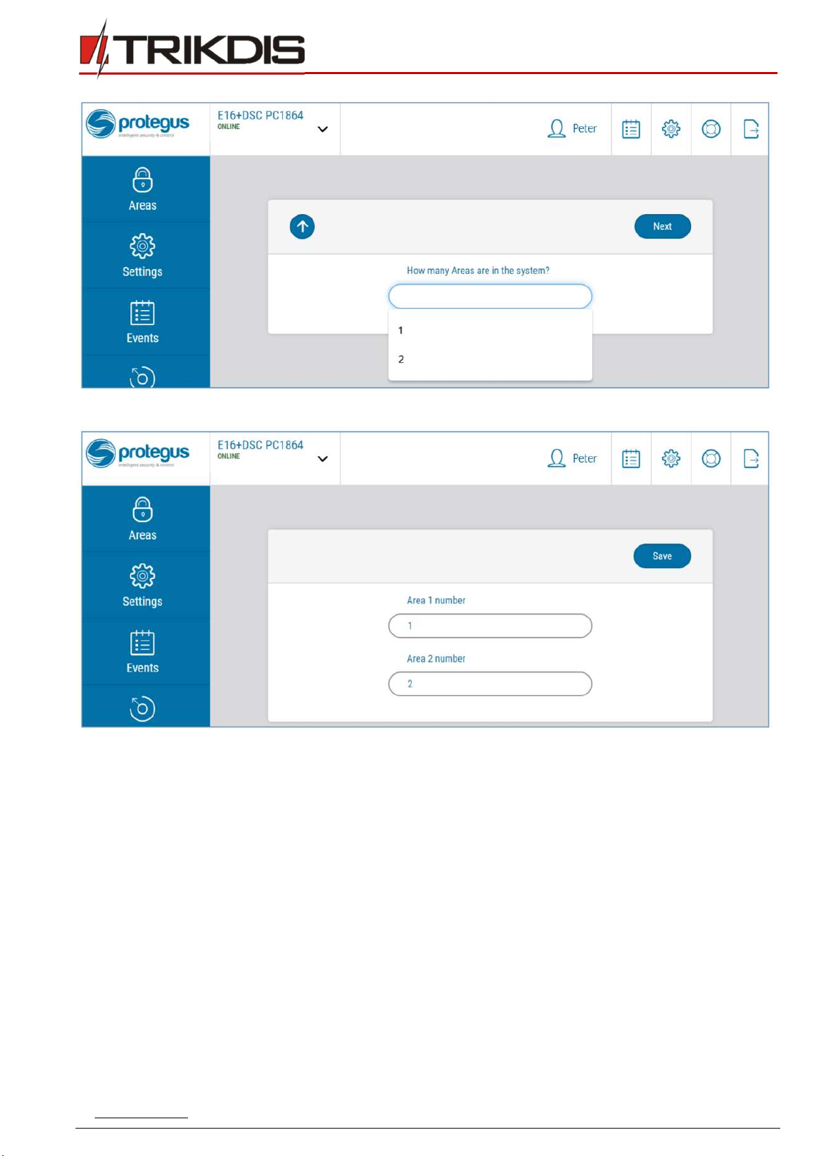
1) In the new window, click Areas in the side menu. In the next window, specify how many alarm system areas (1, 2,
3) are in the system and press Next.
www.trikdis.com 17 February, 2020
“Ethernet”
communicator
E
16
2) In the new window, identify what is the number for each of the specified areas in the security system and press Save.
3) In the side menu press Settings and in the newly opened window press Settings. Select the box Arm/Disarm with PGM
and specify which area the output will control. One PGM output can control only one area.

www.trikdis.com 18 February, 2020
“Ethernet”
communicator
E
16
4) Select Level or Pulse, depending on the type of control panel keyswitch zone. You can also change the duration of the
pulse interval if it is required for the connected control panel.
5) For additional security, you can select Use Application password for ARM/DISARM. Then after pressing the button to
arm/disarm the alarm system, a window for entering the app password will open.
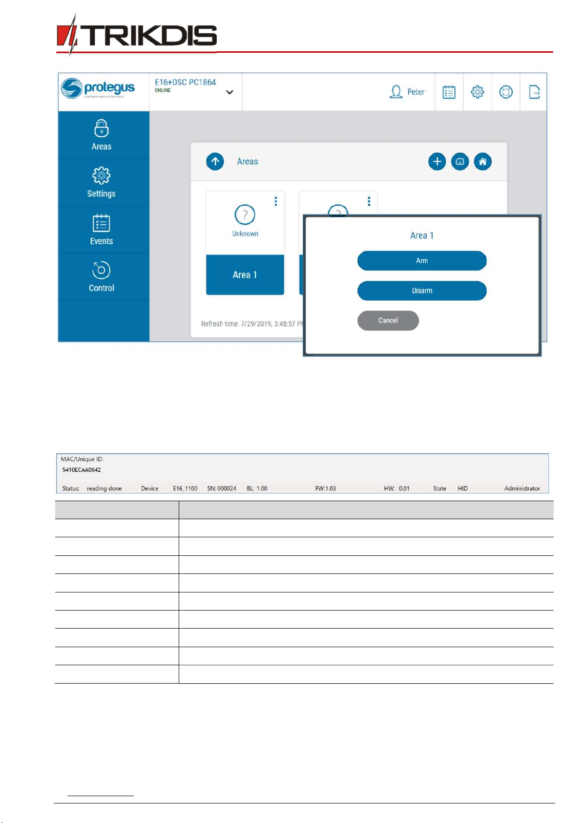
5.3 Arming/disarming the alarm system with Protegus
1) To control the system, open the Areas window.
2) In the Areas window click the Area button. In the pop-up window select the action (arm or disarm the security system
area).
3) If requested, enter the user code or Protegus password.
www.trikdis.com 19 February, 2020
“Ethernet”
communicator
E
16
6 TrikdisConfig window description
6.1 TrikdisConfig status bar description
After connecting the E16 and clicking Read [F4], TrikdisConfig will provide information about the connected device in the status
bar:
Object Description
Unique ID Device IMEI number
Status Operating condition
Device Device type (E16 should be shown)
SN Device serial number
BL Browser version
FW Device firmware version
HW Device hardware version
Status Connection to program type (via USB or remote)
Administrator Access level (shown after access code is approved)
After pressing Read [F4], the program will read and show the settings which are set in the E16. Set the necessary settings
according to the TrikdisConfig window descriptions given below.
www.trikdis.com 20 February, 2020
“Ethernet”
communicator
E
16
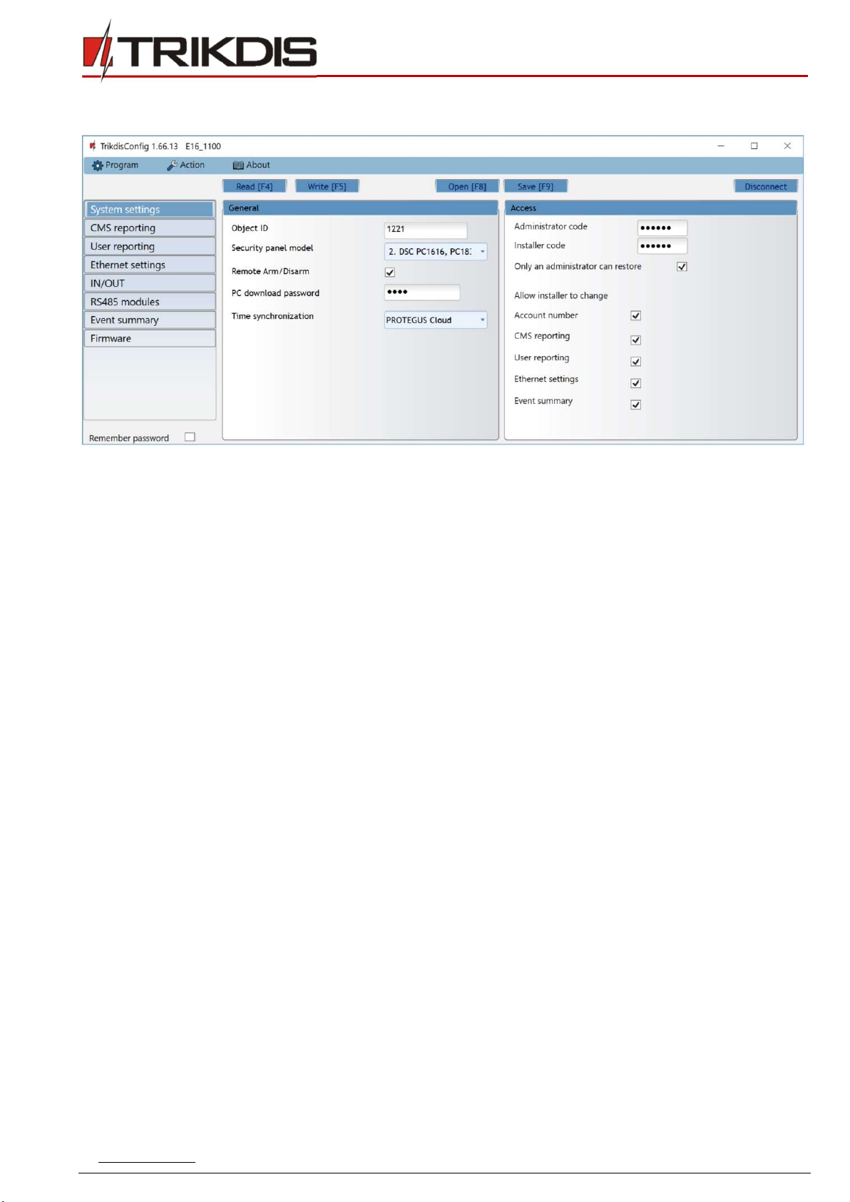
6.2 “System settings” window
“General” settings group
Object ID – if the events will be sent to the CMS (Central Monitoring Station), enter the account number provided by the
CMS (4 characters hexadecimal number, 0-9, A-F. Do not use FFFE, FFFF Object ID.).
Select the Security Panel model that will be connected to the communicator.
Remote Arm/Disarm - when the checkbox is selected, the E16 will directly control the control panel remotely. This setting
will be visible only for directly controlled panels. For direct control of the control panels you need to change the panel
settings, as described in section 4 “Programming the control panel”.
PC download password - for the direct control of Paradox and Texecom control panels you need to enter the PC/UDL
password. It must match the password that was entered in the control panel. How to change this password is described
in section 4 “Programming the control panel”.
Time synchronization - select which server to use for time synchronization.
“Access” settings group
When setting up the communicator E16 there are two levels of access for, the administrator and the installer:
Administrator code - allows you to access all configuration fields (default code - 123456).
Installer code - limited access for configuring the communicator (default code - 654321).
Only an administrator can restore - if the box is checked, factory settings can be restored only by entering the
administrator code.
Allow installer to change – the administrator can specify which settings can be changed by the installer.
Table of contents
Other Trikdis Cell Phone manuals

Trikdis
Trikdis G16 User manual

Trikdis
Trikdis G10D User manual

Trikdis
Trikdis G16T User manual

Trikdis
Trikdis FireCom User manual

Trikdis
Trikdis E16T User manual

Trikdis
Trikdis G09 User manual

Trikdis
Trikdis G10 User manual

Trikdis
Trikdis GET User manual

Trikdis
Trikdis E10T User manual

Trikdis
Trikdis G10 User manual


