Trikdis G09 User manual
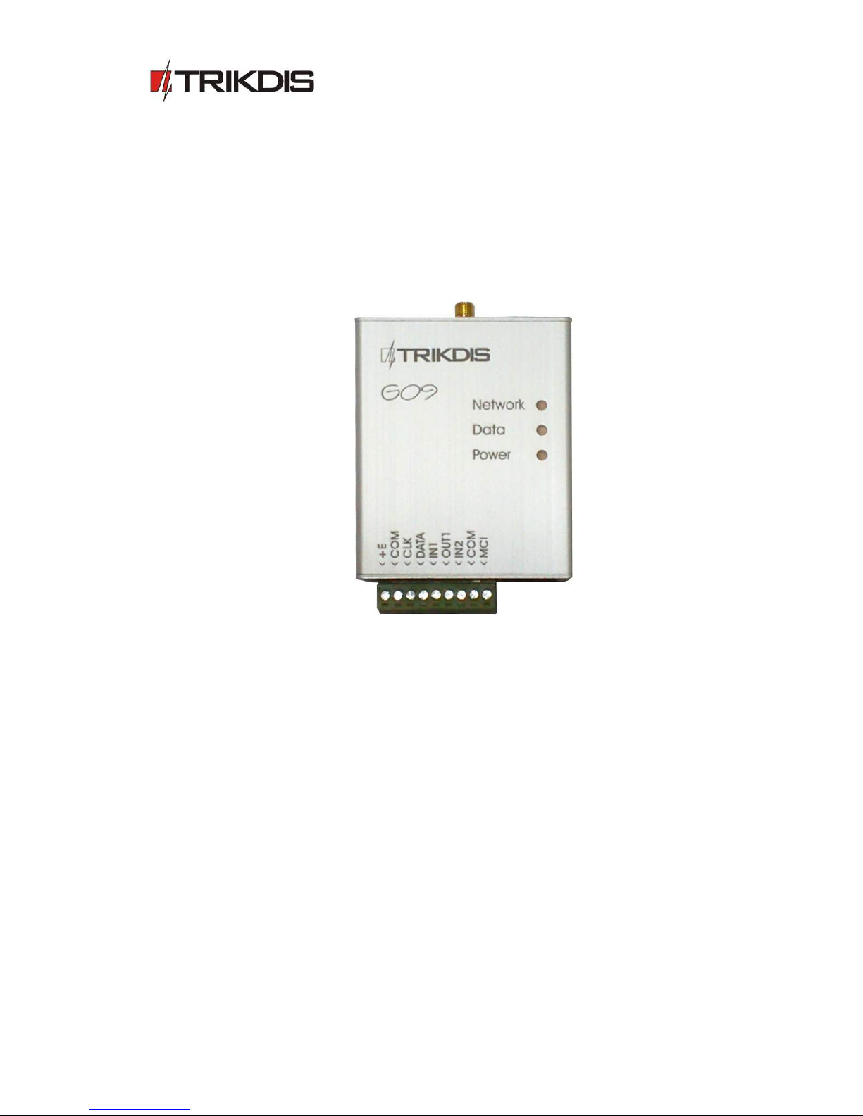
GSM communicator G09
(v.1.61)
User Manual and Installation Guide
Draugystes g. 17,
LT-51229 Kaunas
E-mail: info@trikdis.lt
www.trikdis.lt

2
Purpose of the document
This document introduces the features of GSM communicator G09, describes its operation,
parameter setting procedure and usage peculiarities.
Contents
Safety requirements
1. GSM communicator G09
3
1.1. Operation description
3
1.2. Technical parameters
4
1.3. Equipment
4
1.4. Overall view of communicator G09
4
1.5. Purpose of contacts
5
1.6. Light indication
5
2. Communicator installation
5
2.1. Installation procedures
5
2.2. Connection diagrams
7
3. Setting operation parameters
8
4. Upgrading communicator firmware
13
5. Remote device control using SMS messages
13
6. Warranty and limitation of liability
14
7. Annex 1. Communicator messages
15
Safety requirements
Be sure to familiarise yourself with this manual before using communicator G09.
Communicator may only be installed and maintained by trained specialists, who possess knowledge about operation of
low voltage and signal transmission devices and their safety requirements.
Communicator G09 must be set up in a limited access area and in a safe distance from sensitive electronic equipment.
Communicator is not resistant to mechanical effects, humidity and aggressive chemical environment.

3
1. GSM communicator G09
GSM communicator G09 is used to send security alarm system signals from the protected object to the IP
receivers operating in SIA standard DC-09 protocol in the monitoring station using GPRS.
Main features:
messages are transmitted to the monitoring station via GPRS and/or via voice channel;
messages transmitted using GPRS are sent in SIA standard DC-09 protocol and match protocol Contact ID
codes;
messages transmitted via voice channel may be sent to PSTN receiver in DTMF tones in SIA standard DC-05
protocol Contact ID codes;
messages are sent via indicated communication channel or, if communication fails – via the backup channel;
ability to send SMS messages to the mobile phones of up to 4 users;
two NC type inputs;
one PGM output, which may be controlled remotely;
operation parameters are set using USB connection and software G10config;
1.1. Operation description
Communicator G09 may be connected to security control panel data bus, its programmable outputs or to control
panel telephone communicator using adequate connection. Information is read, converted to corresponding Connect ID
protocol codes and transmitted via communication channels set during the programming. Messages are sent to the
monitoring station and/or user mobile phones.
Communicator sends messages regarding status changes in the external circuit of inputs IN1 and IN2. Message
transmission may be suspended temporarily by setting input IN1 to control mode.
Communicator controls power supply and, in case of the limits being exceeded, generates and sends appropriate
messages and signals about it using light indicators.
Two technologies are supported for message transmission to the monitoring station: GPRS and/or voice channel
sending DTMF tones. SMS text messages are sent to users.
Messages are using GPRS technology in TCP/UDP protocols following SIA standard DC-09 requirements.
Received or generated message is sent via set main channel. Communicator sends messages to users once a
message reception confirmation is received from the monitoring station receiver. If confirmation is not received in time,
message transmission is repeated several times, and if unsuccessful, carried out via the backup channel (if such is set).
Messages may be sent to four user mobile phones using SMS messages. Every security panel message is attributed
with a understandable SMS text message. SMS messages may be distributed among the different users according to a
sent message type.
Communicator may perform a continuous communication control of receiving equipment by periodically sending
communication test signals, to which reception confirmation is being received. When communication via the main
channel fails (reception confirmation is not received), messages are being transmitted via the backup channel.
Communicator will periodically try to restore communication via the main channel according to the parameters set
during the programming.
Communicator output OUT1 status changes when facing communication or operation problems. Operation mode is
set during the programming.
Received or generated messages is directed to a MCI data bus. MCI data bus is designated for message transmission
via several different communication channels. MCI data bus messages are received only by compatible devices: SP131,
G10, E10, T10.
Communicator messages are received by the receiver in the monitoring station.
Messages sent via IP channels are received by an IP receiver which is able to receive and process messages sent in
standard SIA DC-09 protocol. Encrypted or not encrypted messages may be sent. Communicator also sends the
communication device identification number, which may match the object identification number or may be original.
Messages sent in DTMF signals are received by PSTN telephone receiver which is able to receive and process
messages sent in standard SIA DC-05 protocol.
4
1.2. Technical parameters
GSM modem frequencies
850 / 900 / 1800 / 1900 MHz
GSM communication technologies
TCP/IP or UDP/IP via GPRS
Voice channel in DTMF tones
Message transmission protocols
SIA DC-09-2007 or SIA DC-09-2012
SIA DC-05 Contact ID
Encryption protocol
AES128, encryption key length 128 bits (16 symbols)
or not encrypted
Inputs
CLK, DATA communication via security panel data bus
IN1 and IN2, input type NC
Programmable output
OUT1, OC type, commutates voltage of up to 30 V and direct current of
up to 1 A
Memory
up to 60 messages
Parameters setting
via USB port
Power supply
DC 10 V ÷ 15 V
Used current
60 ÷ 100 mA (on standby),
up to 500 mA (while sending data)
Workplace
Air temperature from -10C to +50C,
Relative humidity up to 80 % when +20C
Measures
65 x 79 x 25 mm
1.3. Equipment
Communicator G09
1 pc.
Adhesive mounting tape (10 cm)
1 pc.
Note:
GSM operator SIM card and GSM antenna with screwed male-type connector are also necessary in order to ensure
operation of the communicator.
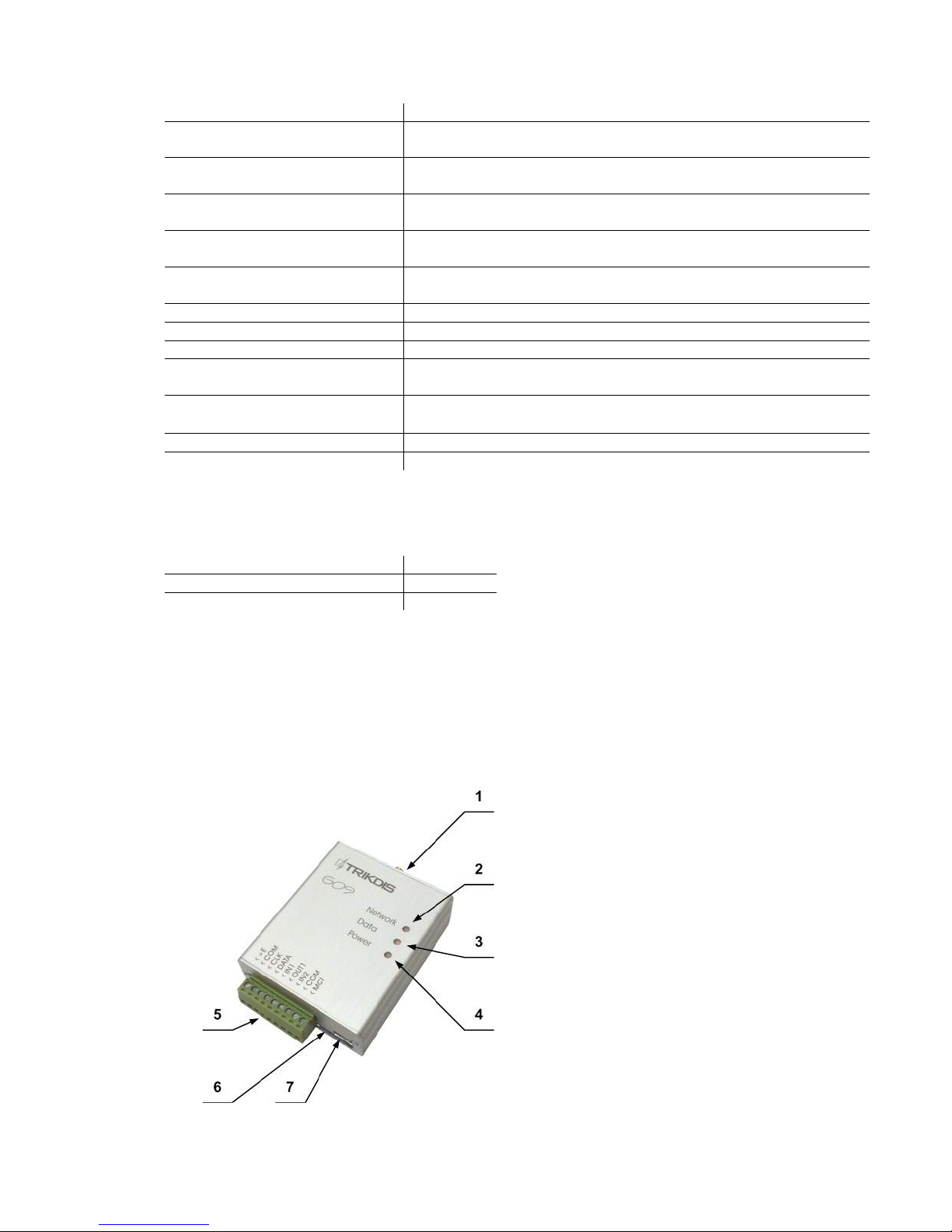
1.4. Overall view of communicator G09
1. GSM antenna connector
2. Indicator Network
3. Indicator Data
4. Indicator Power
5. Terminal block
6. USB connection for programming
7. SIM card slot

5
1.5. Purpose of contacts
Contact
Purpose
+E
+12 V power supply terminal
COM
General terminal
CLK
Synchronisation signal terminal
DATA
Data signal terminal
IN1
1st input terminal (type NC)
OUT1
1st output terminal (type OC)
IN2
2nd input terminal (type NC)
COM
General terminal
MCI
MCI data bus terminal
1.6. Light indication
Light indication
Status
Description
Network
denotes connection with
the GSM network status
Green flashing
Connecting to the GSM network
Green light
Communicator is connected to the GSM network
Yellow flashing
The amount of yellow flashes denotes GSM connection
strength
Yellow light
A message is being sent
Data denotes data
exchange
OFF
No messages or problems
Red flashing
SIM card problem
Red flashing intensely
Incorrect communicator settings
Green flashing
Data is being received
Green light
Unsent messages in memory
Red light
Problem with message sending
Power
denotes power supply
status, microprocessor
operation and
programming mode.
Green flashing
Power supply and microprocessor are in operation,
voltage is regular
Yellow flashing
Insufficient power supply voltage (below 11.5 V),
microprocessor is in operation
Green and yellow flashing
in turns
Programming mode
2. Communicator installation
2.1. Installation procedures
Action
Notes
1. Set communicator operation
parameters.
Refer to information laid out in section Setting operation
parameters.
For example, to receive all messages via one channel, e.g. via GPRS,
it is enough to:
see G10config Main window. Enter communicator (object)
identification number into the field Object ID and PING
signal and Test message sending periods into fields GPRS
PING time and Test time;
see G10config GPRS window. Select the GPRS transmission
channel in the list GPRS, enter static IP address of the
monitoring station and the port number in the fields IP
address and Port, enter the access point name (APN) of the
GPRS network in which the SIM card, that is inserted into
the communicator, operates in the field APN.
Note: Enter DNS value if server IP name is indicated instead of
the IP address.
Indicate message encryption key in the field Encryption key
if sent messages are encrypted. It must match the IP

6
receiver‘s message decryption key.
2. Insert an active SIM card.
Refer to your mobile network operator with regard to the SIM card.
It is not recommended to use pre-paid SIM cards.
3. Fix the communicator into the
control panel case using M3x6
screws, adhesive mounting tape or
plastic holder PH.
Position and measures of the holes to be drilled in the casing for
mounting the communicator and the antenna:
Positions and measures of the holder PH and holes for mounting:
4. Screw the GSM antenna.
5. Connect communicator to security
control panel according to the
diagram.
See section Connection diagrams.
6. Turn on the power supply.
7. Check light indicators to evaluate
whether the strength of the GSM
connection is sufficient.
Sufficient level is level 5 (5 yellow flashes by light indicator
Network). Use a different type antenna if the GSM connection level
is insufficient.
8. Check whether communicator is
sending messages according to the
parameters set during the
configuration.
A message must be sent and received at the indicated IP address.
Check whether all SMS messages are received if messages are sent
to the mobile phone.
7
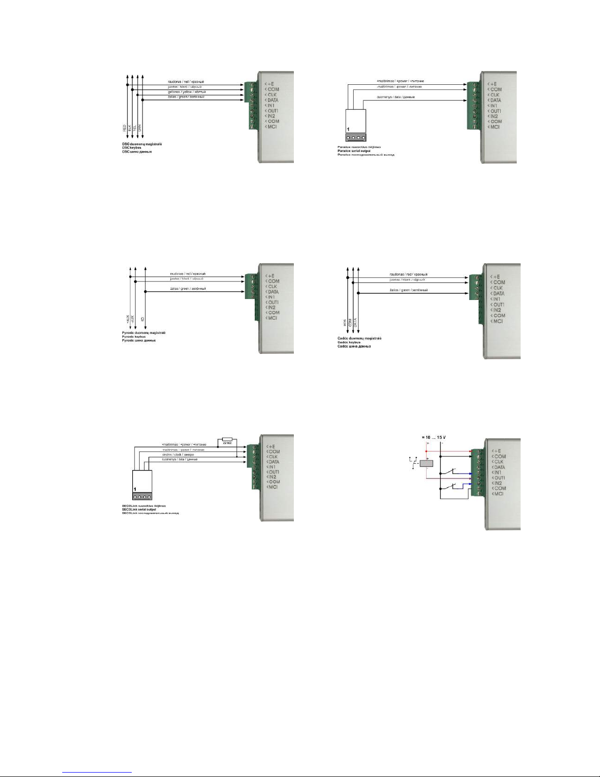
2.2. Connection diagrams
Connecting to DSC Power Series security control
panels:
PC1616, PC1832, PC1864 PC585, PC1565, PC5020.
Connecting to Paradox security control panels:
SPECTRA SP5500, SP6000, SP7000, 1727, 1728, 1738,
MAGELLAN MG5000, MG5050,
DIGIPLEX EVO48, EVO192, EVO96, NE96,
ESPRIT E55, 728ULT, 738ULT.
Connecting to Pyronix Matrix Series security control
panels:
MATRIX 424, MATRIX 832, MATRIX 832+, MATRIX 6,
MATRIX 816.
Connecting to Caddx security control panels:
NX-4, NX-6, NX-8.
Connecting to SECOLink security control panels:
PAS832 (communicator firmware must G10 v1.4X or
newer)
NC inputs and OC output connection diagram

8
3. Setting operation parameters
Operation parameters of communicator G09 are set using software G10config. Software may be found on
www.trikdis.lt.
1. Connect the communicator G09 to a computer using a USB cable.
Note:
A USB driver must be installed on the computer. A USB driver installation window Found New Hardware
Wizard should appear on OS MS Windows during the first cable connection between the communicator and the
computer. Download OS MS Windows USB driver installation file USB_COM.inf from the website www.trikdis.lt.
Select Yes, this time only when prompted and click Next. A new window Please choose your search and installation
options will open. Click Browse and select the location where USB_COM.inf is saved. To finish the USB driver
installation follow remaining installation wizard commands.
2. Run G10config.
3. Select Connect in the menu.
Select the USB port to which the communicator is connected in
the list Port.
Note: the particular USB port to which the communicator is
connected appears only when the two are connected.
Select the desired working language in the list Language.
4. Click Connect [F2/F8]
Indicator Power should flash green and yellow in turns when
communicator G09 is connected to a computer.
Connection status Connected is displayed in the G10config status
bar alongside the information about the connected communicator.
Remote control phone
numbers
Settings for what may be
edited upon connecting
as a user
Parameters for
connecting via USB

9
5. Click Read [F7].
Enter the access code (default – 1234) when prompted and
click OK.
Click Remember if you want the software to remember your
access code. The prompt window will not appear next time.
Tick Save access code for software to remember the password and not require for it next time.
Click Restore [F11] to restore the communicator to factory settings. When prompted, click Yes.
Select Main in the menu and set desired parameters:
Object ID Field to enter the four-digit identification number;
Hex Tick if hexadecimal numbers will be used for entering the object ID;
SIM card PIN code Field for SIM card PIN code. Leave the field empty if PIN code request is disabled;
User code Field to enter the user code. Only those operation parameters that are allowed to be edited by
the administrator can be edited when logging in with the user code;
Admin code Field to enter the admin code. All operation parameters can be edited when logging in with the
admin code. Also, possibilities for editing the operation parameters for those logging in with the
user code may be limited;
Communicator type
Serial number of the communicator
Communicator firmware version

10
GPRS PING time Communicator will check GPRS communication with the receiver by sending test signals NULL in
a specified frequency;
CSD PING time Communicator will check communication with the receiver by sending test signals PING via the
voice channel in a specified frequency;
Test time Communicator will check communication with the monitoring station by sending test messages
TEST in a specified frequency;
Return to primary after
Used if both communication channels to the monitoring station are selected – main and backup.
Enter the time interval value after which the communicator will try to restore the
communication via the main channel (when using the backup communication channel);
Backup reporting after ... attempts
Used if both communication channels to the monitoring station are selected – main and
backup. Enter the number of times communicator will try to send a message via the main
communication channel and upon failure will start sending messages using the backup
communication channel;
Works with security control panel ...
Select the type of the security control panel to which communicator G09 is connected. Choose INTERFACE C11 if a
connection C11 or C14 will be used with the communicator. Choose INTERFACE Cx if extender
CZ6 will be connected;
IN1 Set the operation parameters of input IN1. Select 24 hour zone from the list to send a message
immediately after input IN1 status changes according to the code indicated in Module events.
Select Control input for communicator to send messages only when an external circuit of input
IN1 is broken;
PGM Select Remote PGM control using SMS message to change output status once a control
command in a SMS message is received (see section Remote module control). Output status
will change when communication via the main channel fails, if Main channel problem is
selected. Output status will change when communication via the backup channel fails, if Backup
channel problem is selected. Select Problem in both channels and output status will change
when communication via both the main and the backup channel fails;
Enter parameters for communication with the monitoring station in menu field GPRS:

11
Primary reporting Select the main communication channel via which the communicator will send messages to the
monitoring station from the list:
Tick GPRS and enter the IP address and the port number of the monitoring station in the fields
Server IP1 address or Domain and Port.
Tick DATA and enter the PSTN receiver phone number in the field Tel.1 in order to send Contact
ID messages in DTMF tones. Phone number is entered with the international country code, but
without the + sign;
Backup reporting Select the backup communication channel from the list. The communicator sends messages via
the backup channel if communication via the main one is lost
Tick GPRS and enter the second IP address and the port number of the monitoring station in the
fields Server IP1 address or Domain and Port.
Tick DATA and enter the PSTN receiver phone number in the field Tel. 2 in order to send Contact
ID messages in DTMF tones. Phone number is entered with the international country code, but
without the + sign;
Protocol Select the message encryption protocol from the list. Protocol is selected according to the
requirements of the IP receiver in the monitoring station;
Enable encryption Tick Enable encryption to enable message encryption. Enter the encryption key (up to 16
symbols) in the field Encryption key. Key must match the decryption key of the receiver.
Enter device identification number in fields Line number, Receiver number and Module ID. If
receiver may distinguish the number, enter the requested parameters, if not, leave default
values;
Contact ID Ping Tick Contact IP Ping and indicate the Contact ID message to carry out the continuous
communication with the monitoring program control. Enter the message if monitoring station is
able to control it. Untick, if not.
IP addresses, port and phone numbers, encryption protocol and key, other parameters may only be submitted by the
station manager
APN GSM network operator access point name;
User Login for connecting to the GSM network;
Password Password for connecting to the GSM network;
DNS1, DNS2 Server names of the domains. Indicate if IP address name is used;
APN, user name, password and DNS values must be submitted by the GSM connection operator the SIM card was
purchased from.
Communicator events Communicator events after which messages are sent are displayed in the table below.
Event
“E” event description
“R” event description
TIME
Internal communicator clock is set
Internal communicator clock is not se
TEST
Periodic communicator TEST message
POWER
Power supply lower than 11,5 V
Power supply restored to 12,6 V
TAMPER_1
Communicator input IN1 circuit is broken
Communicator input IN1 circuit is restored
TAMPER_2
Communicator input IN2 circuit is broken
Communicator input IN2 circuit is restored
CZ6_Zone_1
Extender CZ6 input IN1 circuit resistance
exceeds limits
Extender CZ6 input IN1 circuit resistance is restored
and does not exceed limits
CZ6_Zone_2
Extender CZ6 input IN2 circuit resistance
exceeds limits
Extender CZ6 input IN2 circuit resistance is restored
and does not exceed limits
CZ6_Zone_3
Extender CZ6 input IN3 circuit resistance
exceeds limits
Extender CZ6 input IN3 circuit resistance is restored
and does not exceed limits
CZ6_Zone_4
Extender CZ6 input IN4 circuit resistance
exceeds limits
Extender CZ6 input IN4 circuit resistance is restored
and does not exceed limits
CZ6_Zone_5
Extender CZ6 input IN5 circuit resistance
exceeds limits
Extender CZ6 input IN5 circuit resistance is restored
and does not exceed limits
CZ6_Zone_6
Extender CZ6 input IN6 circuit resistance
exceeds limits
Extender CZ6 input IN6 circuit resistance is restored
and does not exceed limits

12
Left-click twice on Contact ID event code or Contact ID restore code to edit an event code and enter new values
in the new window (click OK to check if correct).
Enter parameter for sending SMS messages to the users in the menu Text SMS reporting:
Telephone Enter user phone numbers T1, T2, T3, T4 to which SMS messages will be sent. Phone numbers
are entered with the international country code, but without the + sign;
Name Select which users will be sent messages after a different type of an event occurs:
Select Alarm/Restore to send SMS messages about zone violations/restorations (event codes
E/R1XX , see Annex 1);
Select Troubles to send SMS messages about system operation problems (event codes E/R3XX,
see Annex 1);
Select Tests to send communication test messages Test via SMS messages (event codes E6XX.
See Annex 1);
SMS encoding Select the desired SMS encoding from the list;
Object ID Enter the object name which will be included in the SMS message text;
Send SMS Select which messages listed in the table Name will be sent to users via SMS messages:
Select All to send messages about all events. Messages will be in English, see . Annex 1;
Select Only described to send messages about events that are listed in tables Users, Zones,
Partitions. These tables should only be used in exceptional cases.
Entries in the table Users are linked with the user codes that are used to arm/disarm the alarm
system. Name of the user will be included in the SMS message, if the user arms/disarms the
alarm system;
Entries in the table Zones are linked with the protected zone events. Zone name specified in the
table will be included in the SMS message, when zone is breached/restored.

13
Entries in the table Partitions are linked with the partitions of the security system into several
independently protected areas. Area name indicated in the table will be included in the SMS
message;
6. Click Save [F6] to move entered values to the communicator G09.
7. Click Disconnect [F8] and unplug the USB cable.
Click Save [F5] to save entered values on the computer. A file with an extension .gst will be created and may be
used in the future as a template to configure other modules.
Click Open [F3] to open previously saved filed with .gst extension.
4. Upgrading communicator firmware
Previously purchased communicator firmware may be upgraded once the manufacturer updates communicator G09
with new operation features:
1. Download the newest G09_vx.xx.prg file from www.trikdis.lt.
2. Connect the communicator G09 to the computer, open G10config and select Firmware in the menu.
3. Click Browse and select file G09_vx.xx.prg saved on the computer in the field Open firmware file.
4. Click Start [F9]. Click Disconnect [F8] once the progress bar fills up. Disconnect the USB cable.
5. Plug in the USB cable back again.
Note:
Firmware upgrade process lasts between 60 to 90 seconds!
Wait until indicator Data stops flashing green and click Connect [F2] and Read [F7]. New communicator
firmware version will be displayed in the software G10config status bar.
5. Remote device control using SMS messages
Send a SMS message to module SIM card number in order to change output OUT1 status. Examples of SMS text
messages are indicated in the table below.
SMS message text
Action
Note
OUTPUT ˽ 1234 ˽ ON
Output status changes to ON
Enter Admin or User access code

14
OUTPUT ˽ 1234 ˽ OFF
Output status changes to OFF
instead of numbers 1234.
Symbol ˽ refers to a space in an SMS
message text.
OUTPUT ˽ 1234 ˽ PULSE=005
Output status changes for an
indicated number of seconds
RESET ˽ 1234
Reboots the module
Notes:
1. Module will change output status upon receiving an SMS message from any phone if table Telephones for
remote programming is empty. Module output status may be changed only from the listed phones if at least
one entry is in the table.
2. Output status may only be change if OUT1 operation mode is set to Remote PGM control using SMS message;
3. Use only capital letters in the SMS message!
6. Warranty and limitation of liability
Manufacturer grants warranty for the product installed and operated according to the manual for 24
months.
- By purchasing the Product, the Buyer agrees that the Product is a security system element informing about the
status of the system. Set up Product does not decrease the possibility of the robbery, fire, burglary or any other
breach of the premises.
- TRIKDIS is not liable in cases of the robbery, fire and other breaches of the premises of the Buyer and/or the
Product user and shall not reimburse the resulting property or non-pecuniary damages.
- By purchasing the product, the Buyer agrees that TRIKDIS sold a Product that satisfies the requirements of the
Buyer.
- TRIKDIS does not guarantee that the Product will operate in the indicated way if the Product is not used in
accordance to its purpose and not set up in accordance to the User manual.
- TRIKDIS is not liable for the Product operation malfunctions, if they have occurred due to the loss of the
GSM/GPRS/Internet connection or due to a failure in the networks of the connection service provider.
- TRIKDIS does not influence and is not liable for the pricing and costs of the GSM/GPRS/Internet connection
operator services.
- TRIKDIS is not liable for the interruption of GSM/GPRS/Internet connection services to the Product buyer and/or
the Product user and the property and non-pecuniary damages incurred thereof.
- TRIKDIS is not liable for the interruption in the electricity supply to the Product buyer and/or the Product user and
the property and non-pecuniary damages incurred thereof.
- TRIKDIS is not liable if the Product Buyer and/or the Product user has not updated their product firmware version
on time.
- There may be some technical inaccuracies, grammatical and typographical errors in the product manual. TRIKDIS
reserves the right to edit, add and/or change the information in the manual.

15
7. Annex 1. Communicator messages
SMS messages sent by communicator G09.
Recorded
event CID
code
Event code
sent to CSP
Text in the Contact ID standard
SIA DC-05-1999.09 code table
SMS message text sent to a user
E/R 100
E 100
Medical Alarm
MEDICAL PANIC ALARM
R 100
E/R 110, 115
E 110
Fire Alarm
FIRE PANIC ALARM
R 100
E/R 120
E 120
Panic Alarm
PANIC ALARM
R 120
E 121
E 121
Duress Alarm
DURESS ALARM
E/R 130 … 149
E 130
Burglary Alarm
ALARM
R 130
Burglary Alarm restore
Alarm restore
E/R 301
E 301
AC Loss
AC Power failure on control panel
R 301
AC Loss restore
AC Power failure restored on control panel
E/R 302, 309
E 302
Low System battery
Battery Power failure on control panel
R 302
Low system Battery restore
Battery Power restored failure on control panel
E/R 321
E 321
Bell 1
Bell trouble on control panel
R 321
Bell 1 restore
Bell trouble restore on control panel
E/R 351
E 351
Telco 1 fault
Phone Line trouble on control panel
R 351
Telco 1 fault restore
Phone Line trouble restored on control panel
E/R 400, 401,
406, 451
E 401
Open by user
OPEN by
R 401
Close by user
CLOSE by
E/R 408
E 408
Quick DISARM
Quick DISARM
R 408
Quick ARM
Quick ARM
E/R 409
E 409
Key switch zone
Key switch zone
R 409
Key switch restored
Key switch restored
E 602
E 602
Periodic test report
Periodic Test
E/R 700
E 700
Time set*
R700
Time isn‘t set*
* Event codes are indicated in ECID code table.
Table of contents
Other Trikdis Cell Phone manuals

Trikdis
Trikdis G17F User manual

Trikdis
Trikdis E16T User manual

Trikdis
Trikdis G16T 3 Series User manual

Trikdis
Trikdis G10 User manual

Trikdis
Trikdis E14 User manual

Trikdis
Trikdis G10D User manual

Trikdis
Trikdis G10T User manual

Trikdis
Trikdis E10T User manual

Trikdis
Trikdis GET User manual

Trikdis
Trikdis G10 User manual


