Trikdis E14 User manual
www.trikdis.lt UAB Trikdis Draugystės g. 17, LT-51229 Kaunas, Lietuva +370 37 408 040 info@trikdis.lt
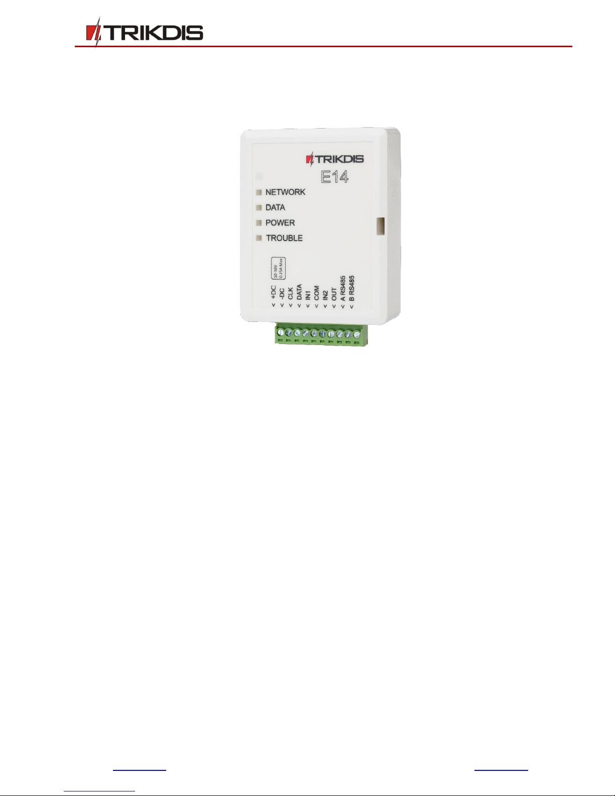
Ethernet communicator E14
USER MANUAL
July, 2018

www.trikdis.com 2July, 2018
Ethernet communicator E14
Contents
SAFETY REQUIREMENTS......................................................................................................................................................... 3
1DESCRIPTION ................................................................................................................................................................ 4
1.1 List of Compatible Control Panels................................................................................................................................ 4
1.2 Technical Parameters.................................................................................................................................................. 5
1.3 Terminal block description .......................................................................................................................................... 5
1.4 Light indication............................................................................................................................................................ 5
1.5 System overview ......................................................................................................................................................... 6
1.6 Package Contents........................................................................................................................................................ 6
2. CONNECT E14 TO TRIKDISCONFIG ................................................................................................................................. 6
2.1 Add communicator in Protegus......................................................................................Error! Bookmark not defined.
2.2 Communication settings with ARC .............................................................................................................................. 8
3. PHYSICAL INSTALLATION............................................................................................................................................... 9
3.1 Wire communicator to panel ...................................................................................................................................... 9
3.1.1 For UTC Interlogix (Caddx) control panels program the following settings........................................................... 10
3.2 (Optional) input connection ...................................................................................................................................... 11
3.3 Connect LAN cable .................................................................................................................................................... 11
3.4 (Optional) output connection.................................................................................................................................... 11
4. ADD COMMUNICATOR IN PROTEGUS ......................................................................................................................... 12
4.1 Additional settings for ARM/DISARM the system via keyswitch zone. ...................................................................... 12
4.2 System management with Protegus ......................................................................................................................... 14
5. CONNECT E14 TO TRIKDISCONFIG ............................................................................................................................... 14
6. SET OPERATION PARAMETERS.................................................................................................................................... 16
6.1 Status bar description ............................................................................................................................................... 16
6.2 System settings window............................................................................................................................................ 17
6.3 Reporting window → ARC reporting tab ................................................................................................................... 18
6.4 Reporting window → Protegus service tab ............................................................................................................... 18
6.5 Event Summary window............................................................................................................................................ 19
6.6 Reset factory settings................................................................................................................................................ 20
7. PERFORM SYSTEM TEST.............................................................................................................................................. 20
8. MANUAL FIRMWARE UPDATE .................................................................................................................................... 20

www.trikdis.com 3July, 2018
Ethernet communicator E14
Safety Requirements
The security alarm system should be installed and maintained by qualified personnel.
Prior to installation, please read carefully this manual in order to avoid mistakes that can lead to
malfunction or even damage to the equipment.
Disconnect power before making any electrical connections.
Changes, modifications or repairs not authorized by the manufacturer shall void your rights under the
warranty.
Please act according to your local rules and do not dispose of your unusable alarm system or its
components with other household waste.

www.trikdis.com 4July, 2018
Ethernet communicator E14
1Description
Communicator E14 is intended to upgrade compatible intruder alarm panels for event signalling via wired
Internet (Ethernet).
Customers are informed about security system events in Protegus app. Communicator can Arm/Disarm
the alarm system via keyswitch zone.
Communicator transmits full event information to Alarm Receiving Centre.
Features
Connection
Direct connection to supported panels for
quick installation and event reporting.
Communications
Simultaneous event reporting to Protegus
Mobile/Web application, allowing user to
remotely monitor and control his alarm
system
Integration with any monitoring software
with Trikdis receivers supporting Surgard
SG-MLR2 protocol
Can send events to universal DC-09
receivers
In case of lost connection with the main IP
address, switches automatically to backup
IP address
Communication in secure encrypted
protocol
Configuration
Quick and easy installation
Remote configuration and firmware
updates
Two access levels for setting of operating
parameters
1.1 List of Compatible Control Panels
Manufacturer
Model
DSC®
PC1616, PC1832, PC1864 PC585, PC1565, PC5020
PARADOX®
SPECTRA SP5500, SP6000, SP7000, 1727, 1728, 1738
MAGELLAN MG5000, MG5050
DIGIPLEX EVO48, EVO192, EVO96, NE96
ESPRIT E55, 728ULT, 738ULT
UTC Interlogix®
NetworX (Caddx) NX-4v2, NX-6v2, NX-8v2, NX-8e
Pyronix®
MATRIX 424, MATRIX 832, MATRIX 832+, MATRIX 6, MATRIX 816
GE Caddx
NX-4, NX-6, NX-8
Secolink
PAS8XX

www.trikdis.com 5July, 2018
Ethernet communicator E14
1.2 Technical Parameters
Parameter
Description
Power supply voltage
10-16 V DC
Current consumption
120 mA (stand-by)
Up to 250 mA (transmitting)
Ethernet connection
IEEE802.3, 10 Base-T, RJ45 socket
Data pack content
Contact ID format codes
Memory
Up to 100 messages
Inputs
2, NC/NO/EOL-2,2 kΩ type
Output
1 OC type, commutating voltage up to 30 V and current up to 500 mA
Operating environment
From -10 °C to 50 °C, with relative air humidity 80% when +20 °C
Dimensions
88 x 62 x 26 mm
1.3 Terminal block description
Contact
Description
+DC
power supply terminal (10-16 V DC positive terminal)
-DC
power supply terminal (10-16 V DC negative terminal)
CLK
Synchronizing signal clamp
DATA
Data signal clamp
IN1
1st input clamp (selectable type)
COM
Common (negative)
IN2
2nd input clamp (selectable type)
OUT
Out terminal (OC type), current up to 500 mA
A RS485
RS485 Bus A contact
B RS485
RS485 Bus B contact
1.4 Light indication
LED
Operation
Description
“Network” displays the
status of connection to the
Internet
Green ON
Communicator is connected to the Internet
Yellow ON
TCP/IP session is open
“Data” displays data transfer
Green ON
Unsent messages present
Red ON
Messages cannot be sent
Green flashing
Messages are being received from the control
panel
Green flashing
Power supply is sufficient,

www.trikdis.com 6July, 2018
Ethernet communicator E14
LED
Operation
Description
“Power” displays power
supply status and the
functioning of the
microprocessor
Yellow flashing
Power supply is not sufficient (≤11,5 V),
“Trouble”
Red ON
Computer network connectivity problems
No flashing/ No
light up
Works without problems
1.5 System overview
1.6 Package Contents
Communicator E14
1 pc.
2. Connect E14 to TrikdisConfig
1. Download TrikdisConfig from www.trikdis.com (in search field type TrikdisConfig), and install it.
2. Remove the E14 cover by using a flat screwdriver as shown below:
Note:
Before configuration, make sure you have all the necessary components:
1) USB Mini-B cable is required for configuration.
2) „CAT-5 Ethernet“ cable (maximum 100 m in length).
3) At least 4 wired cable to connect communicator to the security alarm system.
4) CRP2 cable to connect communcicator to the Paradox control panel‘s Serial Port.
5) Flat screwdriver.
6) User Manual for control panel to which Trikdis communicator will be connected.
Missing components order separately from your local distributor.

www.trikdis.com 7July, 2018
Ethernet communicator E14
3. Connect E14 to your computer via USB Mini-B cable.
4. Run the configuration software TrikdisConfig. The software will automatically recognise E14 and will
open a window for communicator configuration.
Click Read [F4] to read the communicators parameters and enter the Administrator or Installer code
in the pop-up window.
Note:
Click Read [F4] to scan and show settings that are recorded on the device.
Press Write [F5] to save settings on the screen to the device.
Click Save [F9] to save settings to the configuration file, which you can then upload to other
devices. This allows you quickly configure several products with the same settings.
Click Open [F8] and browse your computer to find the configuration file to set up the
communicator from a saved configuration file.
To restore the factory settings, press Restore button at the bottom left of the window.
2.1 Communication settings with Protegus
In the “System Settings” window:
1) Select Panel type that will be connected to the communicator.
In the window “Reporting”tab “Protegus Service”:
www.trikdis.com 8July, 2018
Ethernet communicator E14
2) Check Enable connection in Protegus service checkbox.
3) Change the Service code for logging in to Protegus, if you want to ask users to add it by adding the
Protegus system in the application (factory default - 123456).
More about other TrikdisConfig E14 settings see 6 " Set operation parameters ".
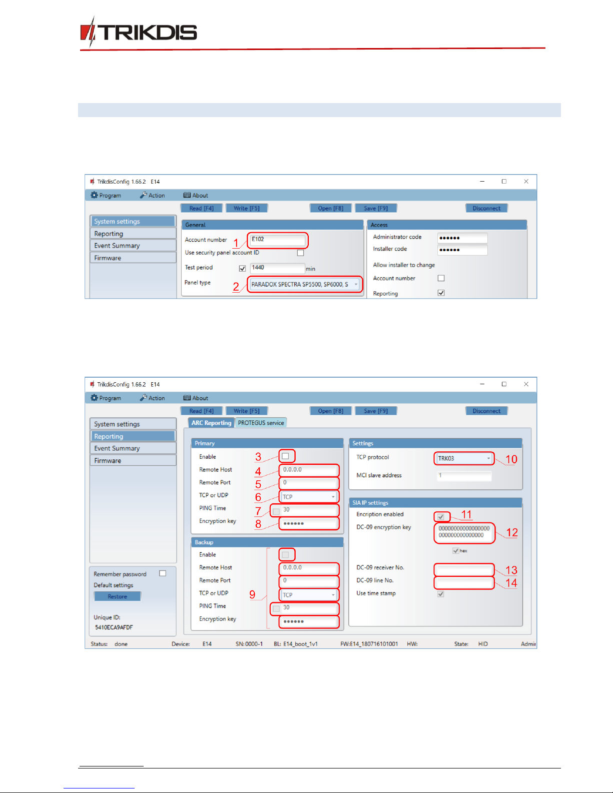
2.2 Communication settings with ARC
In the “System Settings” window:
1) Enter Account Number.
2) Select Panel type that will be connected to the communicator.
In the window "Reporting", tab "ARC Reporting" primary communication channel:
3) Enable –enable primary communication channel.
4) Remote host –enter receiver IP address.
5) Remote port –enter the receiver port number on the network.
6) TCP or UDP –select which protocol (TCP or UDP) should be sent messages.

www.trikdis.com 9July, 2018
Ethernet communicator E14
7) PING Time –PING signal transmission period.
8) Encryption key –enter encryption key that is set in the receiver.
9) (Recommended) Configure the Backup Channel Settings.
10)TCP protocol –select which encoding protocol will be use: TRK (for TRIKDIS receivers), DC-09_2007
or DC-09_2012 (for universal receivers).
11)Encryption enabled –select protocol
12)DC-09 encryption key –enter encryption key that is set in the receiver.
13)DC-09 receiver No. - –enter receiver number.
14)DC-09 line No. –enter receiver line number.
If you selected DC-09 message transmission encoding, in addition in the „Send to ARC“ window, on the
Settings tab, enter the object, line and receiver numbers.
In the window “Reporting” tab “Protegus Service”:
15)Check Enable connection in Protegus service checkbox.
16)Change the Service code for logging in to Protegus, if you want to ask users to add it by adding the
Protegus system in the aplicacion (factory default - 123456).
More about other TrikdisConfig E14 settings see 6 " Set operation parameters ".
3. Physical installation
3.1 Wire communicator to panel
Following the provided schematics connect the communicator to the control panel.

www.trikdis.com 10 July, 2018
Ethernet communicator E14
Important:
In Protegus app one PGM output can be assigned to control one Area (1 PGM - 1 Area; 2
PGM - 2 Areas) regardless of how many areas are controlled by same keyswitch zone in
panel.
Set which Area will be controlled by Protegus in system Settings. There select the checkbox
Arm/Disarm with PGM1, and the number of Area, which you want to control.
In Protegus Areas window, you will see all areas available in the system, with controllable
areas highlighted.
3.1.1 For UTC Interlogix (Caddx) control panels program the following settings
In order for communicator E14 to work with Caddx security control panels NX-4v2, NX-6v2, NX-8v2, NX-8e,
control panels` locations 23 and/or 37 must be set as shown in the table below. When there are more than
one partition in NX-8v2, NX-8e, also program locations 90, 93, 99, 102, 105, 108.
To enter program mode by default:
1. Press [*8 9713] and enter device number (by default 0).
2. Using control panel`s installation manual, set locations and features of segment.
www.trikdis.com 11 July, 2018
Ethernet communicator E14
If you want to select all eight features of a segment, press 1, 2, 3, 4, 5, 6, 7, 8. Symbol * shows that feature
is turned off.
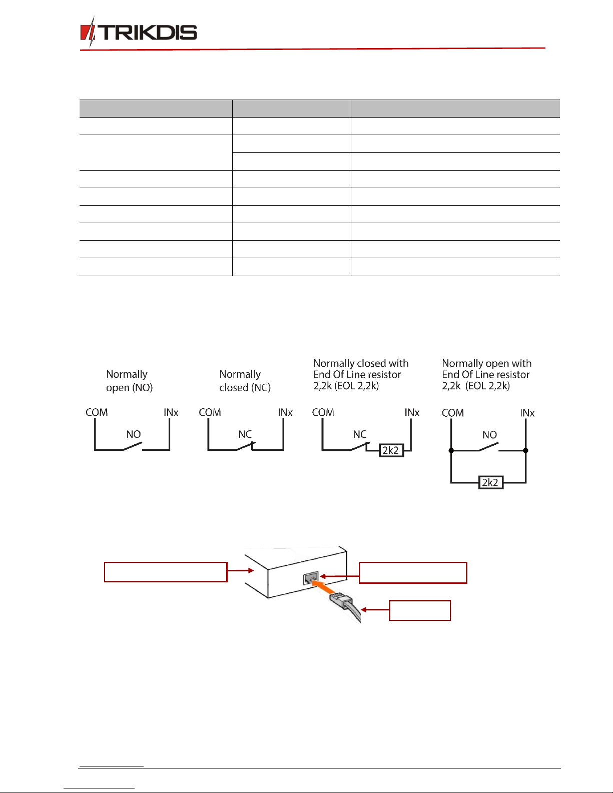
3.2 (Optional) input connection
The communicator contains two input terminals (IN1, IN2) for connection of sensors. Settings for input
connection type and reports on activations are described in 6.5 Event summary. Wire the inputs according
to these schematics:
3.3 Connect LAN cable
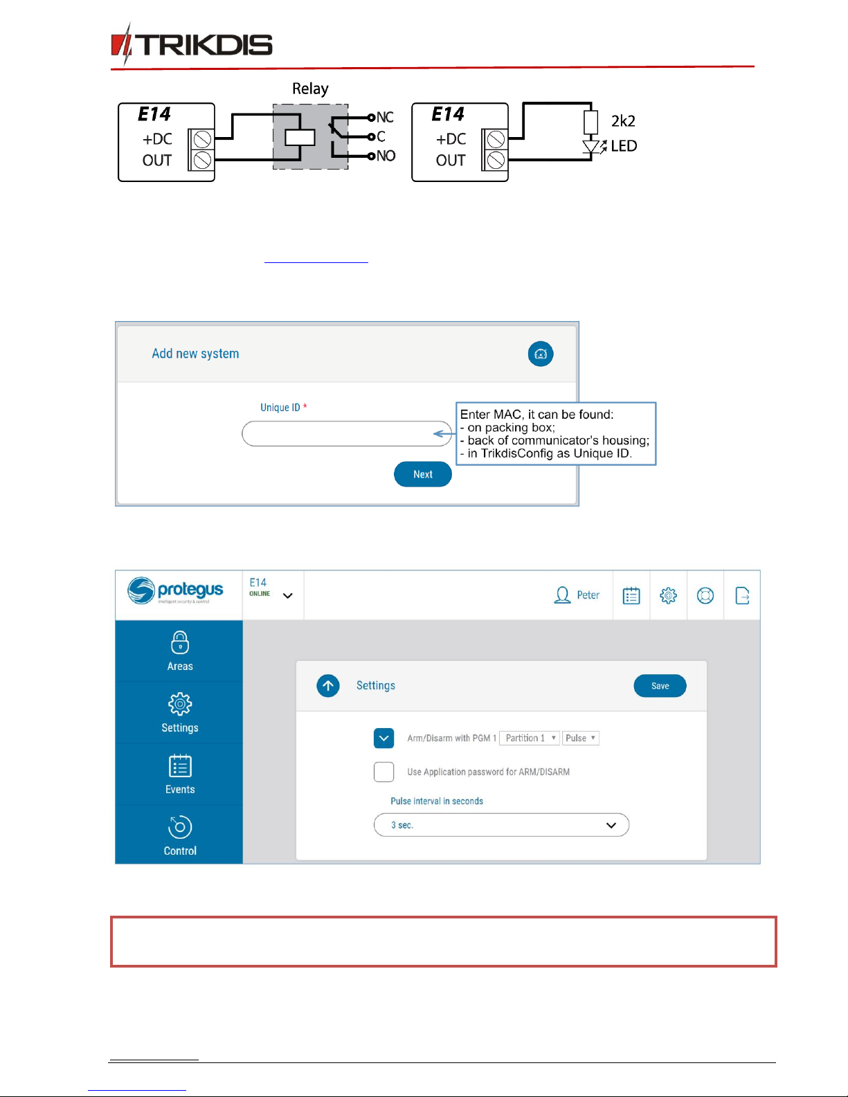
3.4 (Optional) output connection
The communicator contains one output terminal (OUT1) for remote control of various devices. To
Arm/Disarm the control panel, connect OUT1 to panel’s momentary keyswitch zone. Settings for output
control are described in 6.2 System settings window. Here is a diagram of how to connect our
recommended Trikdis relay RBI:
Location
Segment
Features of segment
23
3
12345678
37 (optional, system events)
3
12345678
4
1234567*
90
3
12345678
93
3
12345678
99
3
12345678
102
3
12345678
105
3
12345678
108
3
12345678
Communicator E14
LAN cable
LAN connection jack
www.trikdis.com 12 July, 2018
Ethernet communicator E14
4. Add communicator in Protegus
1. Log in or sign in to www.protegus.eu.
2. Add the system to the Protegus: press Select system; next Add new system +, and enter the required
data as shown below (you can skip fields Name, Address and fill it later).
3. (Optional) If you will use remote arm/disarm feature, in Protegus main window, choose Settings tab
and next windows choose Settings then tick the checkbox: Arm/Disarm with PGM1.
4.1 Additional settings for ARM/DISARM the system via keyswitch zone.
IMPORTANT:
Control panels area, to which E14 output OUT is connected, must be set as keyswitch
zone.
Follow the instructions below if the control panel is not directly managed, but with a E14 PGM output
switching keyswitch zone.
www.trikdis.com 13 July, 2018
Ethernet communicator E14
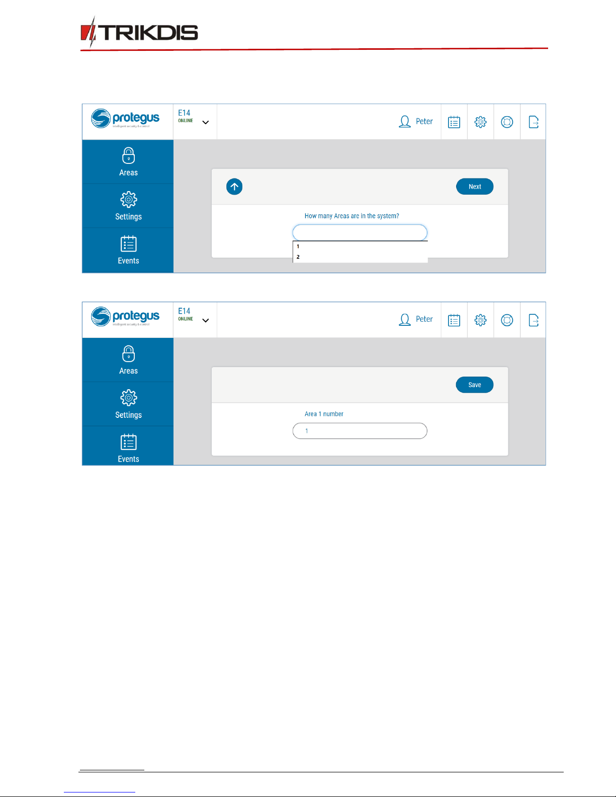
1. After entering the IMEI/Unique ID number, click Next. In the new window, click on the Areas in the
side menu. In the window that appears, specify how many areas (1 or 2) are in the system and press
Next.
2. In the new window, specify the number of each area in the system and click on Save.
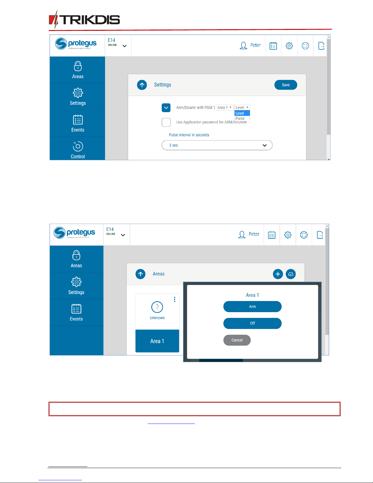
3. In the side menu, press Settings and in the opened window, press Settings. Check the box
ARM/DISARM with PGM1 and specify which area will be controlled with output. One PGM output
can control one area (PGM 1 - Area 1, PGM 2 - Area 2).
4. Select Level or Pulse, depend on control panel keyswitch type. You can also change duration of the
Pulse interval if it is required for the connected control panel.
www.trikdis.com 14 July, 2018
Ethernet communicator E14
4.2 System management with Protegus
1. To control the system, go to the Areas window.
2. In the Area window, click on the area button. In the popup window, select an action (ARM or OFF
the alarm area).
3. On request enter the user code or Protegus password.
5. Connect E14 to TrikdisConfig
Communicator can be configured using TrikdisConfig software for MS Windows via USB cable or remotely.
Important:
To use remote configuration function, Protegus service must be enabled.
1. Download TrikdisConfig from www.trikdis.com (in search field type TrikdisConfig), and install it.
2. Connect the communicator to TrikdisConfig:
www.trikdis.com 15 July, 2018
Ethernet communicator E14
a. Using USB cable: run the configuration software TrikdisConfig. The software will automatically
recognise the connected device and will open a window for communicator configuration; or
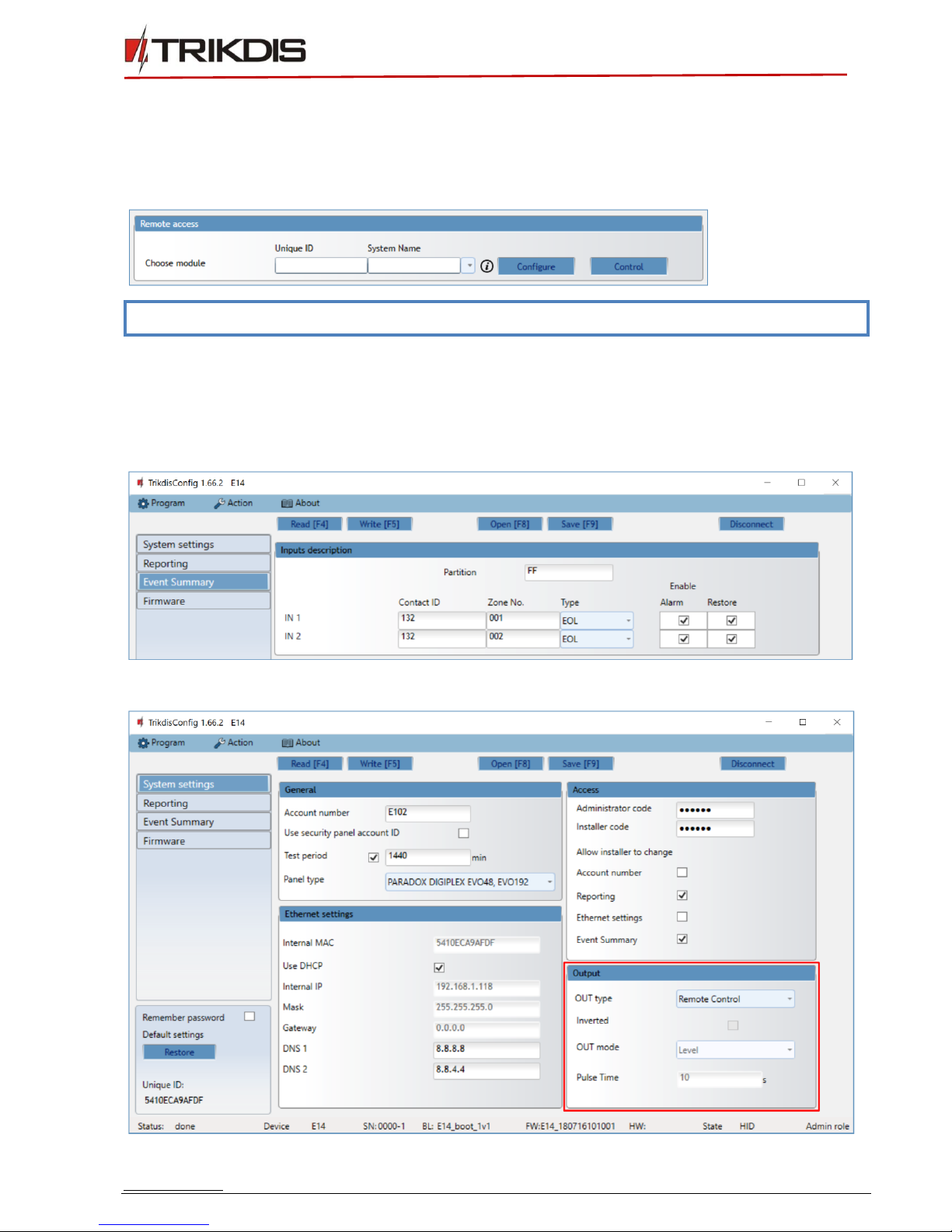
b. Remotely: run the configuration software TrikdisConfig. In section Remote access, field Unique ID
enter MAC address of communicator (MAC address is provided on the product package).
(Optional) in the field System Name enter the desired name to the communicator. Press Configure.
Note:
When a new communicator firmware is released, TrikdisConfig will offer to upgrade it.
3. Click Read [F4] to read the communicators parameters and enter the Administrator or Installer code
in the pop-up window. In order for the program to remember the code, check the box next to
Remember password.
4. In new window, Event Summary, zones can be controlled. Also, (in all tabs) refresh time can be
selected.
5. In System settings tab, PGM outputs can be controlled –turned off/on.

www.trikdis.com 16 July, 2018
Ethernet communicator E14
6. Set the required parameters for E14 and click Write [F5]. To disconnect from E14, click Disconnect
and exit from TrikdisConfig.
6. Set operation parameters
6.1 Status bar description
Once the communicator parameters are read, the status bar will display information about the device:
Name
Description
Unique ID
MAC number of the device
Status
Action status
Device
Device type
SN
Serial number
BL
Bootloader version
FW
Firmware version
HW
Hardware version
State
Connection status
Admin
Access level (shows up after access code is confirmed)
Note:
If administrator code is set as default (123456), it is not required to enter it and the request
window will not appear.
To set up the communicator from a saved configuration file, click Open [F8] and browse your
computer to find the configuration file.
www.trikdis.com 17 July, 2018
Ethernet communicator E14
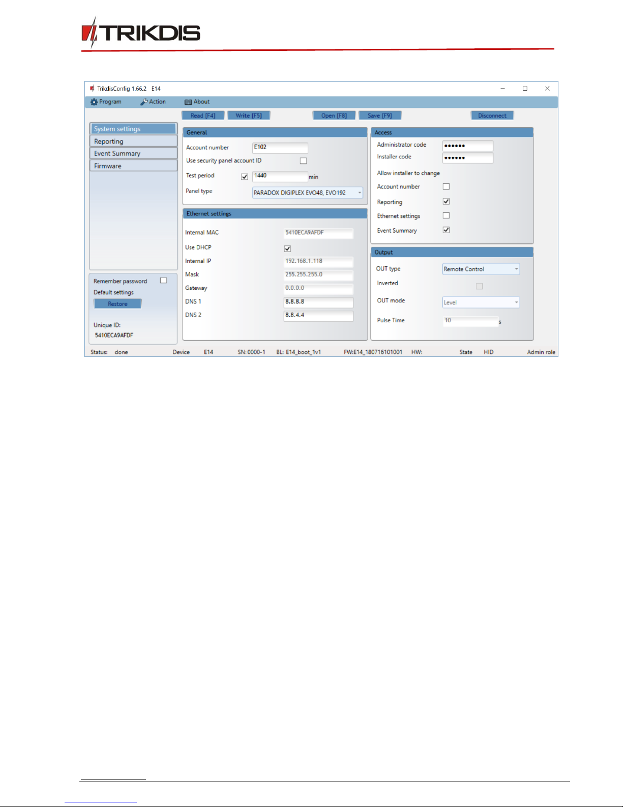
6.2 System settings window
General
•Enter system Account number (4 symbols hexadecimal number) or select Use security panel account
ID checkbox.
•Test period: periodic test messages will be sent according to a time interval set in this section.
•Select control Panel type.
Ethernet settings
•Internal MAC - unique communicator identifier code.
•Select Use DHCP checkbox for communicator to register automatically to the network.
oIf automatic registration is unsuccessful, enter Internal IP address, subnet Mask, Gateway address
and DNS service manually.
Access Settings
•Administrator code - allows full access to the configuration.
•Installer code - allows limited access for installer to the configuration. Administrator can allow the
installer to change:
oAccount number;
oReporting;
oEthernet settings;
oEvent summary.
Output
•Choose output operation type from list OUT type.
•Select Inverted checkbox if output function should be inverted.
•OUT mode:

www.trikdis.com 18 July, 2018
Ethernet communicator E14
oPulse: a status will take time as indicated in Pulse Time (pulse period in seconds) field.
oLevel: a status will change and remain the same until the next command.
6.3 Reporting window → ARC reporting tab
Primary and Backup settings
•To have connection via Primary or Backup channels select Enable checkboxes.
•Fill in fields for Remote Host,Remote Port.
•Choose reporting protocol TCP or UDP.
•Enable PING Time and set time between signals in seconds (required for communication control).
•Enter Encryption key (six-symbol hexadecimal number).
Settings
•Choose TCP protocol encryption type.
SIA IP parameter settings
Encryption enabled –if the DC09_2012 TCP protocol is selected, then encryption can be enabled.
DC09-2012 encryption key –indicates the encryption key.
DC09-2012 receiver No. –receiver’s number is indicated.
DC-09 line No. –specify the receiver line number.
Use time stamp –the time will be included in the message if the field is checked.
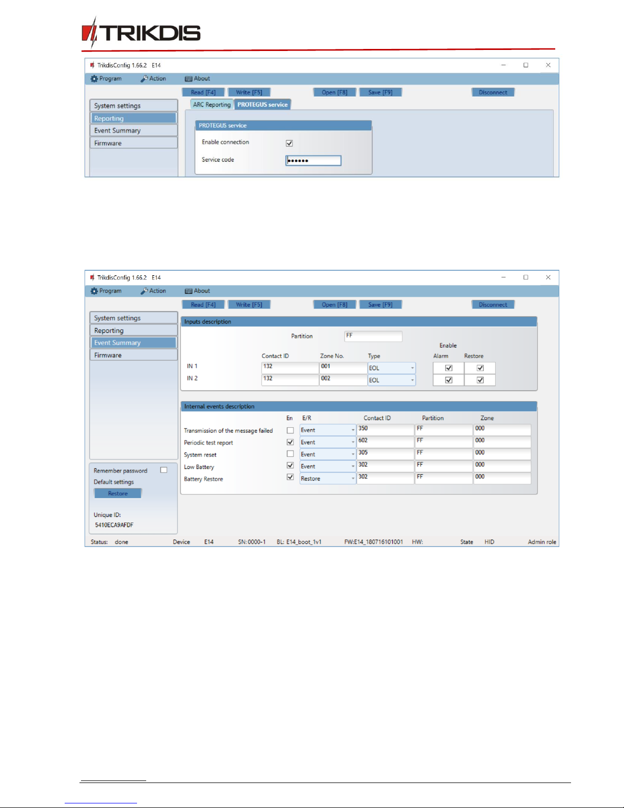
6.4 Reporting window → Protegus service tab
Protegus service allows users to remotely monitor and control the communicator with Android, iOS and
Web apps. It also enables remote configuration of the device via TrikdisConfig.
For more information about PROTEGUS service visit www.protegus.eu.
www.trikdis.com 19 July, 2018
Ethernet communicator E14
•Enable the Protegus cloud service at Reporting →PROTEGUS service tab.
•For additional security enter Service code (default is 123456). If the Service code is changed, you will
need to enter it, when adding the communicator to Protegus.
6.5 Event Summary window
Input description
•To set contact ID event codes to inputs fill in fields:
oPartition;
oContact ID - customize event code or leave the default value;
oZone No –set which zone corresponds to IN 1 or/and IN 2;
•Select Type of inputs (NO, NC, EOL).
•Enable - select Alarm to receive report when event occurs; select Restore to receive report when
input line will restore.
Internal events description
•E/R: To describe internal events, select event type (Event or Restore) and describe Contact ID code,
Partition and Zone as necessary.

www.trikdis.com 20 July, 2018
Ethernet communicator E14
6.6 Reset factory settings
To restore the communicator’s factory defaults, you need to click the Restore button in the TrikgisConfig
window.
7. Perform system test
1. After configuration and installation is complete, perform a system test. Activate an event in the
control panel, and make sure that the event arrives to the alarm receiving centre or is received by
the mobile application.
2. To test communicator inputs, activate it and make sure that the correct messages arrives to
recipients (app users).
3. To test the communicator output, please activate it remotely or initiate the activating event.
8. Manual firmware update
The communicator firmware can be updated or changed manually. After an update, all the previous
communicator parameters will remain the same.
Note:
If there is an installed antivirus software on your computer, it might block automatic
firmware update option. In this case, you must reconfigure your antivirus software.
When writing firmware manually, it can be changed to a newer or older version. To update:
1. Run TrikdisConfig.
2. Connect the communicator via USB cable to the computer or connect to the communicator remotely.
a. If newer firmware version exists, the software will offer to download the newer firmware version
file.
Table of contents
Other Trikdis Cell Phone manuals

Trikdis
Trikdis Ethernet E16 User manual

Trikdis
Trikdis E10T User manual

Trikdis
Trikdis FireCom User manual

Trikdis
Trikdis G10D User manual

Trikdis
Trikdis E10Tv2 User manual

Trikdis
Trikdis GET User manual

Trikdis
Trikdis E16T User manual

Trikdis
Trikdis G10 User manual

Trikdis
Trikdis G10 User manual

Trikdis
Trikdis G16T 3 Series User manual


