Trikdis G17F User manual

GSM communicator G17F
INSTALLATION MANUAL
UAB “TRIKDIS”
Draugystės str. 17,
LT-51229 Kaunas
LITHUANIA
E-mail: info@trikdis.lt
Webpage: www.trikdis.lt

©1997-2017 Trikdis 2 www.trikdis.com
GSM communicator G17F
Contents
SAFETY REQUIREMENTS.................................................................................................................................................3
DESCRIPTION.........................................................................................................................................................4
SPECIFICATIONS ........................................................................................................................................................4
COMMUNICATOR BOARD ............................................................................................................................................5
PURPOSE OF TERMINALS.............................................................................................................................................5
LIGHT INDICATION OF OPERATION.................................................................................................................................5
BEFORE YOU BEGIN....................................................................................................................................................6
CONNECT G17F TO TRIKDISCONFIG .......................................................................................................................6
USING USB CABLE: ...................................................................................................................................................6
REMOTELY:..............................................................................................................................................................6
STATUS BAR DESCRIPTION ...........................................................................................................................................7
SET OPERATION PARAMETERS ..............................................................................................................................7
SYSTEM OPTIONS WINDOW.........................................................................................................................................7
USERS WINDOW .......................................................................................................................................................8
MODULES WINDOW ..................................................................................................................................................8
ZONES WINDOW →ZONES SETTINGS TAB ......................................................................................................................8
ZONES WINDOW →ZONES REPORTING TAB ...................................................................................................................9
PGM WINDOW →OUTPUTS TAB.................................................................................................................................9
PGM WINDOW →REPORTING TAB..............................................................................................................................9
REPORTING WINDOW...............................................................................................................................................10
SYSTEM EVENTS WINDOW →EVENTS TAB....................................................................................................................10
SYSTEM EVENTS WINDOW →REPORTING TAB ...............................................................................................................11
EVENTS LOG WINDOW .............................................................................................................................................11
PHYSICAL INSTALLATION PROCESS ......................................................................................................................12
INSERT SIM CARD INTO THE HOLDER...........................................................................................................................12
MOUNTING ...........................................................................................................................................................12
WIRING DIAGRAMS..................................................................................................................................................12
4.3.1 Wiring to fire control panel.............................................................................................................................................. 12
4.3.2 Input connection .............................................................................................................................................................. 13
4.3.3 Wiring example with iO expanders.................................................................................................................................. 13
REMOTE CONTROL ..............................................................................................................................................14
SMS COMMANDS LIST .............................................................................................................................................14
5.1.1 PGM control with DTMF .................................................................................................................................................. 15
ADD COMMUNICATOR IN PROTEGUS..................................................................................................................15
TEST COMMUNICATOR PERFORMANCE ..............................................................................................................15
MANUAL FIRMWARE UPDATE.............................................................................................................................15

©1997-2017 Trikdis 3 www.trikdis.com
GSM communicator G17F
Safety requirements
The security or fire alarm system should be installed and maintained by qualified personnel.
Prior to installation, please read carefully this manual in order to avoid mistakes that can lead to malfunction or
even damage to the equipment.
Disconnect power supply before making any electrical connections.
Changes, modifications or repairs not authorized by the manufacturer shall void your rights under the warranty.
Please act according to your local rules and do not dispose of your unusable alarm system or its
components with other household waste.

©1997-2017 Trikdis 4 www.trikdis.com
GSM communicator G17F
Description
Communicator G17F can upgrade any fire alarm panel for event signaling via cellular network.
When input is violated, the communicator transmits an event message to Alarm Receiving Centre (ARC).
Communicator can also inform customers about security system events in Protegus apps or with SMS messages.
Features
Specifications
Parameter
Description
GSM modem frequencies
850 / 900 / 1800 / 1900 MHz
3G modem frequencies
800 / 850 / 900 / 1900 / 2100 MHz
LTE modem frequencies
700 / 800 / 900 / 1800 / 2100 / 2600 MHz
Power supply voltage
9-32 VDC
Current consumption
50 mA (standby)
Up to 200 mA (transmitting)
Transmission protocols
TRK
Communication with ARC
TCP/IP or UDP/IP, SMS
Memory
Up to 60 messages
Inputs and outputs
3 inputs,
3 double purpose contacts for setting either input or
output functionality
Selectable type inputs: NC, NO, EOL (10kΩ)
Event log memory
Up to 1000 events
Event transmission
Contact ID codes
Parameter configuration
Locally via USB port or remotely
Operating environment
Temperature from -10 °C to 50 °C, relative humidity –
up to 80% at +20 °C
Communicator dimensions
65 x 77 x 25 mm
Weight
0.08 kg
Communications
One main communication channel
Main channel has two back-up channels
Connection control with ARC
Event messages are transmitted in Contact ID codes
Event reporting to Protegus apps
Event reporting via SMS messages up to eight users in user
friendly SMS messages
Inputs and outputs
RS485 connection
3 selectable type inputs: NC, NO, EOL (10kΩ), 3 double purpose screw terminals for setting either input
or output functionality
Using iO series expanders it is possible to expand inputs number up to 12
Outputs can be controlled via:
oMobile/Web Protegus application or
oSMS/Call
Configuration
Quick and easy installation
Remote configuration and firmware updates

©1997-2017 Trikdis 5 www.trikdis.com
GSM communicator G17F
Communicator board
Purpose of terminals
Terminal
Description
+DC
+9 - +32 VDC power supply
-DC
Common (negative)
A RS485
RS-485 connection positive contact (enables connect iO and iO-WL expanders)
B RS485
RS-485 connection negative contact (enables connect iO and iO-WL expanders)
COM
Common (negative)
X IN
3 selectable type inputs
X I/O
Double purpose terminal: Xnd selectable type input or Xst open-collector (OC)
output (pre-set as NO type input by default)
Light indication of operation
Indicator
Light Status
Description
Network
Off
No connection with GSM network
Green solid with
yellow blinking
Communicator is connected to GSM network.
Number of flashes (from 0 to 5) shows signal strength. Sufficient
signal strength is level 2 (two yellow flashes)
Data
Green solid
Sending message
Yellow solid
Unsent event messages is presented in buffer
Power
Green blinking
Power supply is on with sufficient voltage and microcontroller
is operational
Yellow blinking
Power supply voltage is insufficient (≤22V), microcontroller is
operational
Green and
yellow blinking
(Configuration mode) Communicator is ready for configuration
Trouble
If red LED is blinking:
1 blink
No SIM card
2 blinks
SIM card PIN code problem (incorrect PIN code)
3 blinks
Can not connect to GSM network
4 blinks
Problem with primary channel
5 blinks
Problem with backup channel
6 blinks
Set Module`s internal clock
7 blinks
Power supply voltage is low
9 blinks
RS485 module malfunction
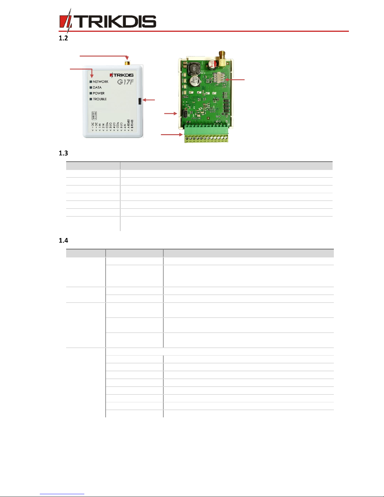
1) GSM antenna SMA connector
2)
Light indicators
3)
Frontal case opening slot
4)
USB Mini-B port for
communicator programming
5)
Nano SIM card slot
6)
Terminal for external
connections
5
6
1
2
3
5
4
6

©1997-2017 Trikdis 6 www.trikdis.com
GSM communicator G17F
Before you begin
Before you begin, make sure that you have the necessary:
1) USB cable (Mini-B type) for configuration.
2) Cable with at least 4 wires for connecting communicator to control panel.
3) Flat-head screwdriver.
4) Sufficient gain GSM antenna.
5) Nano SIM card registered to GSM network.
6) Particular security control panel`s installation manual.
Order them separately from your local distributor.
Connect G17F to TrikdisConfig
Communicator can be configured using TrikdisConfig software for MS Windows OS via USB cable or remotely.
1) Download TrikdisConfig from www.trikdis.com (in search field type TrikdisConfig), and install it.
2) Connect the communicator to TrikdisConfig:
Using USB cable:
Carefully open the casing with flat-head screwdriver as shown below:
a) Insert screwdriver into the slot (red arrow). (it is unnecessary to put in screwdriver`s head to the bottom of
the casing).
b) Hold the casing`s bottom part with one hand and gently push screwdriver to the left side.
c) Plug in USB cable. Run the configuration software TrikdisConfig. The software will automatically recognize
connected communicator and will open a window for communicator configuration.
Remotely:
a) Run configuration program TrikdisConfig.
b) In section, Remote access, field Unique ID enter IMEI address of communicator (IMEI address is provided on
the product package).
c) (Optional) in the field System Name enter the desired name to the communicator. Press Configure.
3) Click Read [F4] to read the communicators parameters and enter the Administrator or Installer code in pop-up
window. For the program to remember the code, check the box next to Remember password.
Note: If administrator code is set as default (123456), it is not required to enter it and the request window will not
appear.
To set up the communicator from a saved configuration file, click Open [F8] and browse your computer to find the
configuration file.
IMPORTANT: To use remote configuration function, Protegus service must be enabled (See chapter: 3.8
Reporting window).
To configure the communicator remotely, insert a registered SIM card with the PIN code request function disabled.

©1997-2017 Trikdis 7 www.trikdis.com
GSM communicator G17F
Status bar description
Once the communicator parameters are read, the status bar will display information about the communicator.
Status bar
Name
Description
IMEI/Unique ID
IMEI number of the communicator
Status
Action status
Device
Communicator type (shows G17F)
SN
Serial number
BL
Bootloader version
FW
Firmware version
HW
Hardware version
State
Connection status
Admin
Access level (shows up after access code is confirmed)
Set operation parameters
System Options window
General
Write an appropriate Object number (4 symbols hexadecimal number, 0-9, A-F).
Object name will be send with SMS messages (max 20 characters, can be letters and numbers).
Test period: periodic test messages will be sent according to a time interval set in this section.
Specify Time synchronization (Communicator will use time according to ARC or GSM modem)
Clear Events after reset ––deletes all unsent events in communicator`s memory after reset.
SMS language –set required language to use specific characters of language in SMS messages
If the communicator registers that the same event messages were triggered, it can suspend those messages and do
not send it to users. Set Suspend event reporting when X same events per XX s.
Restore event reporting after –set time after which event reporting suspension will be canceled. Time limit –999
min.
SIM card
Enter SIM card PIN.
Enter APN –network name.
If it is required, enter network name and password in fields Login, Password.
Access codes
Administrator code –(default code 123456) allows full access to the configuration (Administrator code must be six
symbols in length, and contain digits or Latin characters only).
Protegus Cloud access Code –(default code 123456), for more safety change it to six symbol code.
SMS password –(default code 123456) password for remote control and programming via SMS messages, (six-digit
SMS password).
IMPORTANT: Ensure the SIM card is working and registered on GSM network before using it.
If GPRS communication is required, ensure mobile data service is enabled. For information on how to enable this
service, please contact your network service provider.

©1997-2017 Trikdis 8 www.trikdis.com
GSM communicator G17F
Users window
User permissions
ID –user identification number
Name –username. In the reports will be visible who has controlled the alarm system and how.
Tel number –user phone number, from which the alarm system will be remotely controlled. Numbers must be
entered with international code.
PGM –when selected, allows control PGM outputs with DTMF tones.
ACK –when selected, communicator will send answer messages after receiving command from user.
FWD –when selected, redirects SMS messages, which are not related to communicator’s work (SIM card balance,
random messages).
SMS answer texts
Answers to the SMS commands can be customized in the SMS answer text field.
Modules window
RS485 modules
ID –module sequence number.
Type –select module (module iO, iO-WL) from modules list.
Serial –mandatory serial six-digit number (set previous step).
Name –give name to the module.
Firmware version –version will be shown when G17F is in working mode and detects module.
Zones window →Zones settings tab
Zones settings
ID –zone number.
Input –identifies input type (internal or external device input) and assigns it to zone.
Definition - if the zone is violated at any time, reports will be immediately generated and sent.
Type –input connection type: NC –normally closed, NO –normally open, EOL –end of line with 10 kΩ resistor.
ARC –enable event reporting to ARC.

©1997-2017 Trikdis 9 www.trikdis.com
GSM communicator G17F
CID Code –zone Contact ID event code (will be set automatically when the zone function is selected).
Zones window → Zones reporting tab
Zones→Zones reporting
This window will be shown only if at least one User is described in the 3.2 Users window.
Zn –zone number with event identification mark.
Zone SMS text –text sent to users in SMS message.
SMS/Call –check how users will be informed about the event, with SMS or/and Call.
PGM window → Outputs tab
PGM → Outputs tab
PGM No –specifies PGM.
PGM output –assign communicator`s or external device`s outputs to PGM.
Output definition –Selection output operation mode.
oRemote control –remote control of peripheral devices (turn on/ turn off).
Pulse Time, s –when dial control is used, pulse duration must be indicated. Duration can be from 0 to 9999 sec.
PGM window → Reporting tab
PGM → Reporting tab
This window will be shown only if at least one User is described in the 3.2 Users window.
PGM –indicates PGM ID and report type (E –Event and R –Restore).
Output SMS text –SMS text will be sent when Output reacts.
User SMS/Call –select how and which users will be informed.

©1997-2017 Trikdis 10 www.trikdis.com
GSM communicator G17F
Reporting window
Primary and Backup channels
Select communication Protocol –TCP/IP, UPD/IP, SMS, Protegus.
oIf the TCP/IP or UDP/IP protocol will be used –enter ARC Domain or IP, Port andEncryption key. Choose
the Backup protocol, and enter required data.
oIf the SMS reporting will be used –enter the receivers SMS phone number (phone numbers must contain
country code, for example +370xxxxxxxx) and Encryption key. In this communication protocol, both backup
channels are disabled.
oIf the Protegus protocol will be used –all settings in the ARC reporting window are set automatically, events
will be reported to Protegus apps (how to set communicator with Protegus apps, see in Add communicator
in Protegus.
The Backup 2 will be enabled when the Backup will be set to operate in the Protocol TCP/IP or UDP/IP. SMS to
receiver at ARC will be sent:
oas soon as a communicator has started working for the first time and;
oafter fail of TCP or UDP communication via both the primary and the first’s backup channel.
Settings
Return to primary after - used if primary communication channel and backup channel to the monitoring station are
selected. Enter the time interval value after which communicator will try to restore the communication via the main
channel.
PING time –the communicator will send to receiver via GPRS communication test signals PING in a set time
period.
SMS PING time –the communicator will send SMS PING messages to receiver to test communication in a set
time period.
Backup reporting after attempts - used if primary communication channel (GPRS_TCP or GPRS_UDP) and
backup channel are selected. Enter the number of times communicator will try to send a message via the primary
channel and upon failure will send messages using the backup communication channel.
DNS1 and DNS2 –we recommending not changing the DNS server addresses.
System events window → Events tab
Event summary → Events
ID –List number of the event.
Event name –the name of the event.
Enable –enable the generation of the event.

©1997-2017 Trikdis 11 www.trikdis.com
GSM communicator G17F
ARC –selected event report will be sent to ARC.
CID code –contact ID number.
SMS event text –received SMS text after CID event is triggered.
SMS restore text –received SMS text after CID event is restored.
System events window →Reporting tab
Event summary → Reporting
This window will be shown only if at least one User is described in the 3.2 Users window.
ID –event number and identification letter (R–restored. E–event).
Event SMS text –text that will be visible in SMS message.
User –users can be informed about selected events with SMS or/and Call.
Events Log window
Events Log
Read Log button–reads registered log.
Clear Log button –deletes event log table`s content.
In the table, Event No, time and Log description can be found. Event log history can show up to 1000 events saved in
G17F memory.
3.12 To write new parameters to the communicator, click Write [F5].
3.13 Disconnect communicator
Click Disconnect to disconnect from roles (installer or admin) while communicator is connected via USB cable to
computer.
If a configuration is done via USB cable, unplug the USB cable, click Disconnect to go back to first window.
Note:
To restore default settings of the communicator, press the Restore button under the Default settings in the
bottom left corner of the configuration window.
To create a configuration file which contains current parameters, click Save [F9].

©1997-2017 Trikdis 12 www.trikdis.com
GSM communicator G17F
Physical installation process
Insert SIM card into the holder
Use only Nano SIM card.
SIM card must be registered to the GSM network if GPRS communication will be used; enable mobile data
service.
To configure the communicator remotely, insert a SIM card with the PIN code request function disabled.
Mounting
To mount the CG17 using screws:
1) take out PCB board;
2) fasten the bottom part with screws to the desired place;
3) place the PCB board back into the case.
Wiring diagrams
4.3.1 Wiring to fire control panel
Following the logic of provided wiring diagram below, connect communicator to the fire control panel:

©1997-2017 Trikdis 13 www.trikdis.com
GSM communicator G17F
4.3.2 Input connection
The communicator contains six inputs terminal for connection of sensors.
NO, Normally Open
Short –Event;
Open - Restore
End of line (EOL10k)
Short –Event;
Restored to 10k –Event restore
NC, Normally Closed
Short –Restore;
Open - Event
4.3.3 Wiring example with iO expanders
4.5 Turn on the power supply.
Note:
Maximum four iO-MOD modules can be connected to one communicator in one system.
Maximum eight iO or/and iO-WL modules can be in one system.
Temperature sensors and iButton key reader is not compatible with G17F.

©1997-2017 Trikdis 14 www.trikdis.com
GSM communicator G17F
Remote control
SMS commands list
SMS Commands are used to control the communicator remotely.
As access code use “SMS password”, “_” represents a space.
SMS command structure: Command_SMSpassword_Data.
Examples
For the exemplary purposes, SMS password is 123456.
To receive information about the communicator:
“INFO_123456”
To turn on the output OUT1:
“OUTPUT1_123456_ON”
To turn on the output OUT1 for 3 seconds:
“OUTPUT1_123456_PULSE=003”
Command
Data
Description
INFO
Request information about the communicator. The response will
include: communicator type, IMEI number, serial number, and
firmware version.
RESET
Restart the communicator.
OUTPUT
x
ON
Turn on the output, where “x” represents output number.
OFF
Turn off the output, where “x” represents output number.
PULSE=ttt
Turn on the output for several seconds, where “x” represents
output number (1) and “ttt” a three–digit number representing
pulse duration in seconds.
PSW
New password
Setting new password
TIME
YYYY/MM/DD,12:00:0
Setting of internal clock
TXTA
Object name
Setting of object name
TXTE
Z1=<Text>
........
Z12=<Text>
Customising of SMS with alarm text:
Z1...Z12 –input number
For example: TXTE 123456 Z1=ALARM in Zone1
TXTR
Z1=<Text>
........
Z12=<Text>
Customising of SMS with restore text:
Z1...Z12 –input number
For example: TXTR 123456 Z1=Restore Zone1
RDR
PhoneNR#SMStext
Readdress SMS messages to specified number.
Phone number must contain “+” and country code.
For example: “RDR 123456 +37061234567#readdressed text”
ASKI
Send SMS message about input statuses.
ASKO
Send SMS message about PGM output statuses.
SETN
PhoneX=PhoneNR#Na
me
Add phone number and assign it to user.
“x” – represents phone number queue number in the list.
Phone number must contain “+” and country code.
Phone number must be separate from user name with #.
PhoneX=DEL
Deletes selected phone number.

©1997-2017 Trikdis 15 www.trikdis.com
GSM communicator G17F
5.1.1 PGM control with DTMF
To control PGM state follow steps below:
Make call to the communicator.
Press output*state# (state can be found in the table below).
DTMF commands:
DTMF code
Function
Description
output*state#
PGM control
Controls specified PGM output and its state.
State:
0 –output off;
1 –output on;
2 –pulse off;
3 –pulse on;
(pulse duration described in TrikdisConfig software, PGM table)
# –this symbol shows code ending.
e.g.:
5*1# –turn on PGM5.
4*3# –turn on PGM4 for time which is described in TrikdisConfig PGM table.
#
Start rewriting
If writing command accidentally made mistake, write * and write command
again.
Add communicator in Protegus
Protegus service is a Web Service for remote intrusion or fire alarm self–monitoring and control of both Trikdis and 3rd
party devices via Web, iOS, or Android apps.
1) Log in or sign in to www.protegus.eu.
2) Add the system to the Protegus: press “Select system”; next “Add new system +”, and enter the required data as
shown below (you can skip fields “Name”, “Address” and fill it later).
Test communicator performance
After configuration and installation is complete, perform a system test:
1) Check if power supply is ON
2) Check network connection (Light indication): sufficient GSM signal strength is level 2 (two yellow flashes of indicator
Network).
3) Activate an event in the control panel, and make sure that the event arrives to the alarm receiving center or is received
in the mobile application.
4) To test communicator input, activate it and make sure that the correct messages arrives to recipients.
5) Carry out alarm signaling tests to make sure that the alarm receiving center receives the signals correctly.
Manual firmware update
The communicator firmware can be updated or changed manually. After an update, all the previous communicator
parameters will remain the same.
When writing firmware manually, it can be changed to a newer or older version. To update:
1) Run TrikdisConfig.
2) Connect the communicator via USB cable to the computer or connect to the communicator remotely.
If newer firmware version exists, the software will offer to download the newer firmware version file.
Enter IMEI (it can be found: on
packing box;
back of communicator`s housing;
in TrikdisConfig as Unique ID).

©1997-2017 Trikdis 16 www.trikdis.com
GSM communicator G17F
3) Select the menu branch Firmware.
4) Press Open firmware and select the required firmware file.
If you do not have the file, the newest firmware file can be downloaded by registered user from
www.trikdis.com , under the download section of the G17F communicator.
5) Press Update [F12].
6) Wait for the prompt of update to complete.
7) Click OK in the prompted window.
Note: If there is an installed antivirus software on your computer, it might block automatic firmware update
option. In this case you must reconfigure your antivirus software.
Other manuals for G17F
1
Table of contents
Other Trikdis Cell Phone manuals

Trikdis
Trikdis G10T User manual

Trikdis
Trikdis GET User manual

Trikdis
Trikdis G16T 3 Series User manual

Trikdis
Trikdis G16 User manual

Trikdis
Trikdis E10Tv2 User manual

Trikdis
Trikdis E10T User manual

Trikdis
Trikdis G16T User manual

Trikdis
Trikdis E16T User manual

Trikdis
Trikdis Ethernet E16 User manual

Trikdis
Trikdis G16 User manual