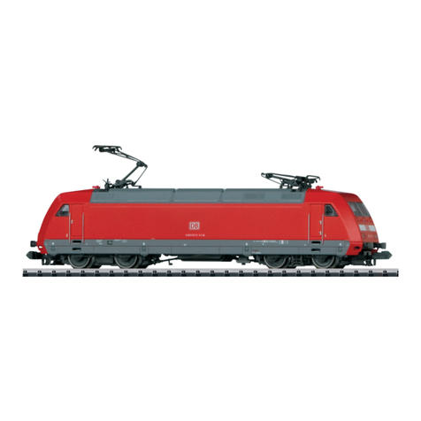
Trix 11141 User manual

Modell der Elektrolokomotive Serie Ae 610
11141
D GB USA F

2

3
Inhaltsverzeichnis Seite
Informationen zum Vorbild 4
Sicherheitshinweise 6
Wichtige Hinweise 6
Funktionen 6
Hinweis zum Digitalbetrieb 6
Schaltbare Funktionen 7
Configurations Variablen (DCC, CVs) 8
Parameter (SX2) 10
Wartung und Instandhaltung 24
Ersatzteile 30
Table of Contents Page
Information about the prototype 5
Safety Notes 12
Important Notes 12
Functions 12
Note on digital operation 12
Controllable Functions 13
Configuration Variables (DCC, CVs) 14
Paramètre (SX2) 16
Service and maintenance 24
Spare Parts 30
Sommaire Page
Informations concernant la locomotive réelle 5
Remarques importantes sur la sécurité 18
Information importante 18
Fonctionnement 18
Remarques relatives au fonctionement en mode digital 18
Fonctions commutables 19
Variables de configuration (DCC, CVs) 20
Parameter (SX2) 22
Entretien et maintien 24
Pièces de rechange 30

4
Informationen zum Vorbild
Anfang der 1950er-Jahre waren die zu bewältigenden Trans-
portleistungen so gestiegen, dass sich die Schweizerischen
Bundesbahnen (SBB) gezwungen sahen, einen neuen Loko-
motivtyp zu entwickeln. Die neue Lok sollte leistungsfähiger,
schneller und vor allem auch leichter sein. So entstand die
Baureihe Ae 6/6, die lange Jahre die Hauptlast des Zugför-
derungsdienstes am Gotthard trug.
Die sechsachsige Lok (Co’Co’) mit einer Leistung von
4.400 kW (6.000 PS) und einer Höchstgeschwindigkeit von
125 km/h war in der Lage, einen Zug von 770 t Gesamt-
gewicht über den Gotthard zu führen. Dies ergab eine
deutliche Fahrzeitverkürzung und Einsparungen, denn zuvor
mussten alle Züge in Doppeltraktion geführt werden.
Insgesamt wurden von dieser leistungsfähigen Lok, die bis
in die Siebziger Jahre dem Güterzugverkehr am Gotthard ihr
Gepräge gab, 120 Stück gebaut. Die ersten 25 Maschinen
erhielten Wappentafeln der Schweizer Kantone, die weite-
ren die Wappen von Patenstädten.

5
Information about the prototype
At the start of the 1950’s the demand for transport had
increased to such a point that the Swiss Federal Railways
(SBB) were compelled to develope a new type of loco-
motive. The new locomotive was designed to be more
powerful, faster and lighter in weight. The result was the
class Ae 6/6 which was the main source of motive power
for years on the Gotthard route.
The six-axle locomotive (Co’Co’) had an output of
4400 kilowatts (6000 hp) and a top speed of 125 km/h
(approx. 78 m.p.h.); it was capable of pulling a 770 ton
train over the Gotthard Pass. This resulted in consider-
ably shorter schedule times and savings, for prevoiously
all trains had to be operated with double headed motive
power.
All total, 120 units of this powerful locomotive were built,
and they left their mark on freight traffic on the Gotthard
route well into the 1970’s. The coats-of-arms for Swiss
cantons were put on the first 25 units, and the coats-of-
arms for sponsoring Swiss citis were put on the rest.
Informations concernant le modèle réel
Au début des années 1950, les puissances de traction
nécessaires étaient devenues tellement importantes que les
Chemins de Fer Fédéraux suisses (CFF/SBB/FFS) s’étaient
vus contraints de développer un nouveau type de locomo-
tive. La nouvelle locomotive devait être plus puissante, plus
rapide et surtout plus légère. C’est aisni que naquit la
série Ae 6/6 qui assura pendant de longues années l’essen-
tiel des services de traction sur le Gotthard.
Cette locomotive à six essieux (Co’Co’) d’une puissance de
4400 kW (6000 CV) avec une vitesse maximum de 125 km/h
était capable de faire franchir le Saint Gotthard à un train
de 770 t de masse totale. Ceci se traduisit par des gains
de temps importants et des économies, car les tractions
devaient auparavant être assurées en double traction.
Au total, ce furent 120 unités de cette locomotive puissante
qui furent construites, marquant de leur image le trafic
marchandises sur la ligne du Saint Gotthard jusqu’aux
années soixante-dix. Les 25 premières machines ont reçu
des blasons de contons suisses, les suivantes des blasons
de villes de parrainage.

6
Sicherheitshinweise
• DieLokdarfnurmiteinemdafürbestimmtenBetriebssys-
tem eingesetzt werden.
• DieLokdarfnichtmitmehralseinerLeistungsquelle
versorgt werden.
• BeachtenSieunbedingtdieSicherheitshinweiseinder
Bedienungsanleitung zu Ihrem Betriebssystem.
• Analog14Volt=,digital22Volt~.
• FürdenkonventionellenBetriebderLokmussdas
Anschlussgleis entstört werden. Dazu ist das Entstörset
14972 zu verwenden. Für Digitalbetrieb ist das Entstörset
nicht geeignet.
• SetzenSiedasModellkeinerdirektenSonneneinstrah-
lung, starken Temperaturschwankungen oder hoher
Luftfeuchtigkeit aus.
• DasverwendeteGleisanschlusskabeldarfmaximal
2 Meter lang sein.
• ACHTUNG! Funktionsbedingte scharfe Kanten und Spitzen.
Wichtige Hinweise
• DieBedienungsanleitungunddieVerpackungsind
Bestandteile des Produktes und müssen deshalb aufbe-
wahrt sowie bei Weitergabe des Produktes mitgegeben
werden.
• FürReparaturenoderErsatzteilewendenSiesichbittean
Ihren Trix-Fachhändler.
• GewährleistungundGarantiegemäßderbeiliegenden
Garantieurkunde.
• Entsorgung:www.maerklin.com/en/imprint.html
Allgemeiner Hinweis zur Vermeidung elektromagnetischer
Störungen:
UmdenbestimmungsgemäßenBetriebzugewährleisten,ist
ein permanenter, einwandfreier Rad-Schiene-Kontakt der
Fahrzeuge erforderlich. Führen Sie keine Veränderungen an
stromführenden Teilen durch.
Funktionen
• EingebauteElektronikzumwahlweisenBetriebmit
konventionellem Gleichstrom-Fahrgerät (max. ±12 Volt),
Trix Systems, Trix Selectrix (SX1) und Selectrix 2 (SX2)
oder Digitalsystemen nach NMRA-Norm.
• AutomatischeSystemerkennungzwischenDigital-und
Analog-Betrieb.
• KeineautomatischeSystemerkennungzwischenden
Digital-Systemen.
• Dreilicht-SpitzensignalmitderFahrtrichtungwechselnd.
• Lokistnicht für funktionsfähigen Oberleitungsbetrieb
vorbereitet.
Hinweis zum Digitalbetrieb
• BeimerstenBetriebineinemDigital-System(SX1,SX2
oder DCC) muss der Decoder auf dieses Digital-System
eingestellt werden. Dazu ist der Decoder einmal in
diesem Digitalsystem zu programmieren
(z.B. Adresse ändern).

7
Schaltbare Funktionen
DC
SX 1
SX 2
DCC
Spitzensignal
F0
ABV, aus
F4

8
CV Bedeutung Wert DCC ab Werk
1 Adresse 1 – 127 3
2 Minimalgeschwindigkeit 0 – 15 10
3 Anfahrverzögerung 0 – 255 3
4 Bremsverzögerung 0 – 255 3
5 Maximalgeschwindigkeit 0 – 127 79
8 Reset 8 131
13 Analog Funktionen; Bit 0 – 7
=
^
F1 – F8 0 – 255 1
14 Analog Funktionen; Bit 0 – 5
=
^
F9 – F12 0 – 63 3
17 ErweiterteAdresse(obererTeil)(CV29,Bit5=1) 0 – 255 192
18 ErweiterteAdresse(untererTeil)(CV29,Bit5=1) 0 – 255 0
19 Traktionsadresse(0=inaktiv,Wert+128=inverseFahrtrichtung) 0 – 127 0
21 Traktions-Modus; Bit 0 – 7
=
^
F1 – F8 0 – 255 0
22 Traktions-Modus; Bit 0 – 1
=
^
FLf – FLr, Bit 2 – 5
=
^
F9 – F12 0 – 63 0
29
Bit0:UmpolungFahrtrichtung
Bit1:AnzahlFahrstufen14-28/126
Bit2:DCCBetriebmitBremsstrecke
DCC-, Selectrix- und Gleichstrombetrieb
Bit5:Adressumfang7Bit/14Bit
0 – 255 14
33 Funktionszuordnung F0 vorwärts 0 – 255 9
34 Funktionszuordnung F0 rückwärts 0 – 255 6
35 Funktionszuordnung F1 0 – 255 0

9
CV Bedeutung Wert DCC ab Werk
36 Funktionszuordnung F2 0 – 255 0
37 Funktionszuordnung F3 0 – 255 16
38 Funktionszuordnung F4 0 – 255 128
39 Funktionszuordnung F5 0 – 255 32
40 Funktionszuordnung F6 0 – 255 0
41 Funktionszuordnung F7 0 – 255 0
42 Funktionszuordnung F8 0 – 255 0
43 Funktionszuordnung F9 0 – 255 0
44 Funktionszuordnung F10 0 – 255 0
45 Funktionszuordnung F11 0 – 255 0
46 Funktionszuordnung F12 0 – 255 0
52 Dimmung Licht 0 – 31 31
54 Dimmung AUX 1 0 – 31 31
55 Dimmung AUX 2 0 – 31 31
Die Werte für die Funktionszuordnung sind folgender Tabelle zu entnehmen. Die Werte können addiert werden.
RG/AUX6 ABL/AUX5 AUX4 AUX3 AUX2 AUX1 LR LV
Wert 128 64 32 16 8 4 2 1

10
par Bedeutung Wert SX2 ab Werk
001 Adresse Einer- u. Zehner-Stelle 0 – 99 1
002 Adresse Hunderter- u. Tausender-Stelle 0 – 99 10
008 Traktionsadresse Einer- u. Zehner-Stelle 0 – 99 0
009 Traktionsadresse Hunderter- u. Tausender-Stell 0 – 99 0
011 Anfahrverzögerung 0 – 255 3
012 Bremsverzögerung 0 – 255 3
013 Maximalgeschwindigkeit 0 – 127 79
014 Mindestgeschwindigkeit 0 – 15 10
018 Geschwindigkeit Rangiergang 0 – 127 79
021 Bremsabschnitte; 1 oder 2 0, 1 0
028 Traktions-Modus; Bit 0 – 7
=
^
F1 – F8 0 – 255 1
029 Traktions-Modus; Bit 0 – 1
=
^
FLf – FLr, Bit 2 – 5
=
^
F9 – F12 0 – 255 3
061 Funktionszuordnung F0 vorwärts 0 – 255 9
062 Funktionszuordnung F0 rückwärts 0 – 255 6
063 Funktionszuordnung F1 0 – 255 0
064 Funktionszuordnung F2 0 – 255 0
065 Funktionszuordnung F3 0 – 255 16
066 Funktionszuordnung F4 0 – 255 128
067 Funktionszuordnung F5 0 – 255 32

11
WerkseinstellungfürSX1:01-732,erweitert:00-274
par Bedeutung Wert SX2 ab Werk
068 Funktionszuordnung F6 0 – 255 0
069 Funktionszuordnung F7 0 – 255 0
070 Funktionszuordnung F8 0 – 255 0
071 Funktionszuordnung F9 0 – 255 0
072 Funktionszuordnung F10 0 – 255 0
073 Funktionszuordnung F11 0 – 255 0
074 Funktionszuordnung F12 0 – 255 0
081 Dimmung Licht 0 – 31 31
083 Dimmung AUX1 0 – 31 31
084 Dimmung AUX2 0 – 31 31
Die Werte für die Funktionszuordnung sind folgender Tabelle zu entnehmen. Die Werte können addiert werden.
RG/AUX6 ABL/AUX5 AUX4 AUX3 AUX2 AUX1 LR LV
Wert 128 64 32 16 8 4 2 1

12
General Note to Avoid Electromagnetic Interference:
A permanent, flawless wheel-rail contact is required in
order to guarantee operation for which a model is designed.
Do not make any changes to current-conducting parts.
Functions
• Built-inelectroniccircuitforoptionaloperationwith
a conventional DC train controller (max. ±12 volts),
Trix Systems, Trix Selectrix (SX1), and Selectrix 2 (SX2),
or digital systems adhering to the NMRA standards.
• Automaticsystemrecognitionbetweendigitalandanalog
operation.
• Noautomaticsystemrecognitionbetweenthedigital
systems.
• Tripleheadlightsthatchangeoverwiththedirectionof
travel.
• Locomotiveisnot equipped for operation off of catenary.
Note on digital operation
• Whenoperatinginadigitalsystemforthersttime(SX1,
SX2, or DCC), the decoder must be set to this digital sys-
tem. To do this, the decoder must be programmed once in
thisdigitalsystem(example:changetheaddress).
Safety Notes
• Thislocomotiveisonlytobeusedwiththeoperating
system it is designed for.
• Thislocomotivemustnotbesuppliedwithpowerfrom
more than one power pack.
• Paycloseattentiontothesafetynotesintheinstructions
for your operating system.
• Analog14voltsDC,digital22voltsAC.
• Thefeedertrackmustbeequippedtopreventinter-
ference with radio and television reception, when the
locomotive is to be run in conventional operation. The
14972 interference suppression set is to be used for this
purpose. The interference suppression set is not suitable
for digital operation.
• Donotexposethemodeltodirectsunlight,extreme
changes in temperature, or high humidity.
• Thewireusedforfeederconnectionstothetrackmaybe
a maximum of 2 meters / 78 inches long.
• WARNING! Sharp edges and points required for operation.
Important Notes
• Theoperatinginstructionsandthepackagingareacom-
ponent part of the product and must therefore be kept as
well as transferred along with the product to others.
• PleaseseeyourauthorizedTrixdealerforrepairsor
spare parts.
• Thewarrantycardincludedwiththisproductspecies
the warranty conditions.
• Disposing:www.maerklin.com/en/imprint.html

13
Controllable Functions
DC
SX 1
SX 2
DCC
Headlights
F0
ABV, off
F4

14
CV Discription Value DCC Factory
Setting
1 Address 1 – 127 3
2 Minimum Speed 0 – 15 10
3 Acceleration delay 0 – 255 3
4 Braking delay 0 – 255 3
5 Maximum speed 0 – 127 79
8 Reset 8 131
13 Analog Functions; Bit 0 – 7
=
^
F1 – F8 0 – 255 1
14 Analog Functions; Bit 0 – 5
=
^
F9 – F12 0 – 63 3
17 Extendedaddress(upperpart)(CV29,Bit5=1) 0 – 255 192
18 Extendedaddress(lowerpart)(CV29,Bit5=1) 0 – 255 0
19 MultipleUnitAddress(0=inactive,Value+128=inversedirection) 0 – 127 0
21 Motive Power Mode; Bit 0 – 7
=
^
F1 – F8 0 – 255 0
22 Motive Power Mode; Bit 0 – 1
=
^
FLf – FLr, Bit 2 – 5
=
^
F9 – F12 0 – 63 0
29
Bit0:Traveldirectionpolarityreversal
Bit1:numberofspeedlevels14–28/126
Bit2:DCCOperationwithbrakingBlock
DCC-, Selectrix and DC power operation
Bit5:addresssize7Bit/14Bit
0 – 255 14
33 Function Assignment F0 forward 0 – 255 9
34 Function Assignment F0 reverse 0 – 255 6

15
CV Discription Value DCC Factory
Setting
35 Function Assignment F1 0 – 255 0
36 Function Assignment F2 0 – 255 0
37 Function Assignment F3 0 – 255 16
38 Function Assignment F4 0 – 255 128
39 Function Assignment F5 0 – 255 32
40 Function Assignment F6 0 – 255 0
41 Function Assignment F7 0 – 255 0
42 Function Assignment F8 0 – 255 0
43 Function Assignment F9 0 – 255 0
44 Function Assignment F10 0 – 255 0
45 Function Assignment F11 0 – 255 0
46 Function Assignment F12 0 – 255 0
52 Dimming of lights 0 – 31 31
54 Dimming of AUX 1 0 – 31 31
55 Dimming of AUX 2 0 – 31 31
The values for the function assignment can be found in the following table. The values can be added.
RG/AUX6 ABL/AUX5 AUX4 AUX3 AUX2 AUX1 LR LV
Value 128 64 32 16 8 4 2 1

16
par Discription SX2 Value Factory
Setting
001 Address for one and ten placeholder 0 – 99 1
002 Address for hundred and thousand placeholder 0 – 99 10
008 Consist address for one and ten placeholder 0 – 99 0
009 Consist address for hundred and thousand placeholder 0 – 99 0
011 Acceleration delay 0 – 255 3
012 Braking delay 0 – 255 3
013 Maximum speed 0 – 127 79
014 Minimum speed 0 – 15 10
018 Speed for switching range 0 – 127 79
021 Braking section; 1 or 2 0, 1 0
028 Traktions-Modus; Bit 0 – 7
=
^
F1 – F8 0 – 255 1
029 Traktions-Modus; Bit 0 – 1
=
^
FLf – FLr, Bit 2 – 5
=
^
F9 – F12 0 – 255 3
061 Function Assignment F0 forward 0 – 255 9
062 Function Assignment F0 reverse 0 – 255 6
063 Function Assignment F1 0 – 255 0
064 Function Assignment F2 0 – 255 0
065 Function Assignment F3 0 – 255 16
066 Function Assignment F4 0 – 255 128
067 Function Assignment F5 0 – 255 32

17
FactorysettingforSX1:01-732,advanced:00-274
par Discription SX2 Value Factory
Setting
068 Function Assignment F6 0 – 255 0
069 Function Assignment F7 0 – 255 0
070 Function Assignment F8 0 – 255 0
071 Function Assignment F9 0 – 255 0
072 Function Assignment F10 0 – 255 0
073 Function Assignment F11 0 – 255 0
074 Function Assignment F12 0 – 255 0
081 Dimming of lights 0 – 31 31
083 Dimming of AUX 1 0 – 31 31
084 Dimming of AUX 2 0 – 31 31
The values for the function assignment can be found in the following table. The values can be added.
RG/AUX6 ABL/AUX5 AUX4 AUX3 AUX2 AUX1 LR LV
Value 128 64 32 16 8 4 2 1

18
Remarques importantes sur la sécurité
• Lalocomotivenepeutêtreutiliséequ‘aveclesystème
d‘exploitationindiqué.
• Lalocomotivenepeutêtrealimentéeencourantquepar
une seule source de courant.
• Veuillezimpérativementrespecterlesremarquessur
la sécurité décrites dans le mode d’emploi en ce qui
concerne le système d’exploitation.
• Analogique14V=,numérique22Volt~.
•
Pour l’exploitation de la locomotive en mode conventionnel,
la voie de raccordement doit être déparasitée. A cet effet,
utiliser le set de déparasitage réf. 14972. Le set de déparasi-
tage ne convient pas pour l’exploitation en mode numérique.
• Nepasexposerlemodèleàunensoleillementdirect,
à de fortes variations de température ou à un taux
d‘humiditéimportant.
• Lecâblederaccordementàlavoieutilisénedoiten
aucun cas dépasser deux mètres.
• ATTENTION! Pointes et bords coupants lors du fonction-
nement du produit.
Information importante
• Lanoticed‘utilisationetl’emballagefontpartieintégrante
du produit ; ils doivent donc être conservés et, le cas
échéant, transmis avec le produit.
• Pourtouteréparationouremplacementdepièces,
adressez vous à votre détaillant-spécialiste Trix.
• Garantielégaleetgarantiecontractuelleconformément
au certificat de garantie ci-joint.
• Elimination:www.maerklin.com/en/imprint.html
Indication d‘ordre général pour éviter les interférences
électromagnétiques:
Lagarantiedel‘exploitationnormalenécessiteuncontact
roue-rail permanent et irréprochable. Ne procédez à aucune
modification sur des éléments conducteurs de courant.
Fonctionnement
•
Module électronique intégré pour exploitation au choix avec
régulateur de marche conventionnel c.c. (max. ±12 volts),
Trix Systems, Trix Selectrix (SX1) et Selectrix 2 (SX2) ou
systèmes numériques conformes à la norme NMRA.
• Reconnaissanceautomatiquedusystèmeentreexploita-
tions numérique et analogique.
• Pasdereconnaissanceautomatiquedusystèmeentre
les systèmes numériques.
•
Feux triples avec alternance selon sens de marche.
• Lalocomotiven‘estpas équipée pour une exploitation
avec alimentation par caténaire.
Remarques relatives au fonctionnement en mode digital
• Unepremièreexploitationensystèmenumérique
(SX1, SX2 ou DCC) exige un réglage correspondant du
décodeur. A cet effet, le décodeur doit être programmé
une fois dans ce système numérique (modification de
l’adresse par ex.).

19
Fonctions commutables
DC
SX 1
SX 2
DCC
Fanal
F0
ABV, désactivé
F4

20
CV Signification Valeur DCC Valeur Parm. Usine
1 Adresse 1 – 127 3
2 Vitesse min 0 – 15 10
3Temporisationd‘accélération 0 – 255 3
4 Temporisation de freinage 0 – 255 3
5 Vitesse maximale 0 – 127 79
8 Réinitialisation 8 131
13 Fonctions analogiques; Bit 0 – 7
=
^
F1 – F8 0 – 255 1
14 Fonctions analogiques; Bit 0 – 5
=
^
F9 – F12 0 – 63 3
17 Adresseétendue(partiesupérieure)(CV29,Bit5=1) 0 – 255 192
18 Adresseétendue(partieinférieure)(CV29,Bit5=1) 0 – 255 0
19 Adressepourlatraction(0=inactif,Valeur+128=directioninverse) 0 – 127 0
21 Mode traction, bit 0 à 7
=
^
F1 à F8 0 – 255 0
22 Mode traction; bit 0 à 1
=
^
FLf à FLr, Bit 2 à 5
=
^
F9 à F12 0 – 63 0
29
Bit0:inversiondepolarité,sensdemarche
Bit1:Nombredecransdemarche14–28/126
Bit2:ExploitationDCCaveczonedefreinage.
DCC-, Selectrix et courant continu
Bit5:tailled‘adresse7Bits/14Bits
0 – 255 14
33 Affectation fonction F0 en avant 0 – 255 9
34 Affectation fonction F0 en arrière 0 – 255 6
35 Affectation fonction F1 0 – 255 0
Table of contents
Languages:
Other Trix Toy manuals

Trix
Trix Minitrix BR 152 User manual

Trix
Trix 141 Hectorrail User manual

Trix
Trix ER 20 EVB User manual

Trix
Trix E 50/BR 150 22154 User manual

Trix
Trix 23436 User manual

Trix
Trix Minitrix BR 232 User manual

Trix
Trix PA-1 User manual

Trix
Trix Minitrix 66300 User manual

Trix
Trix minitrix V80, BR 280 User manual

Trix
Trix MINITRIX Stadthaus User manual
Popular Toy manuals by other brands

Pro Boat
Pro Boat Miss Budweiser owner's manual

GRAUPNER
GRAUPNER AMIGO V manual

REVELL
REVELL AH-64D Longbow Apache Assembly manual

Eduard
Eduard F9F-2 S.A. quick start guide

Fisher-Price
Fisher-Price Spinnyos CMN78 instruction sheet

Hachette
Hachette AGORA BISMARCK THE LEGENDARY BATTLESHIP Build instructions