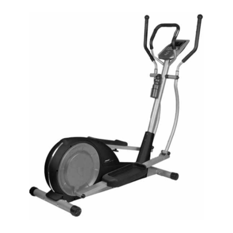
Trojan GLIDE 150 User manual
Other Trojan Elliptical Trainer manuals
Trojan
Trojan PULSE 260 User manual
Trojan
Trojan IMAGE 350 User manual
Trojan
Trojan DUAL 500 Installation guide

Trojan
Trojan DUAL 500 Installation guide
Trojan
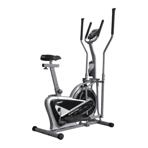
Trojan GLIDE CYCLE 220 User manual
Trojan
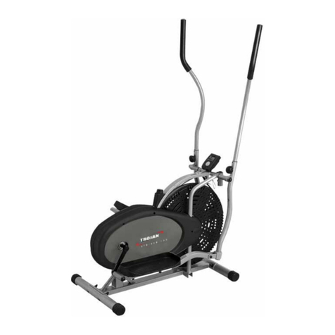
Trojan STRIDER 100 Installation guide
Trojan
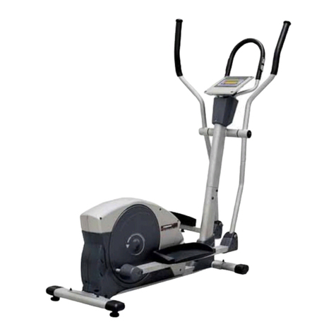
Trojan X-TRAINER 400 Installation guide

Trojan
Trojan GLIDE CYCLE 220 User manual

Trojan
Trojan SOLO 200 Care instructions and assembly User manual
Trojan
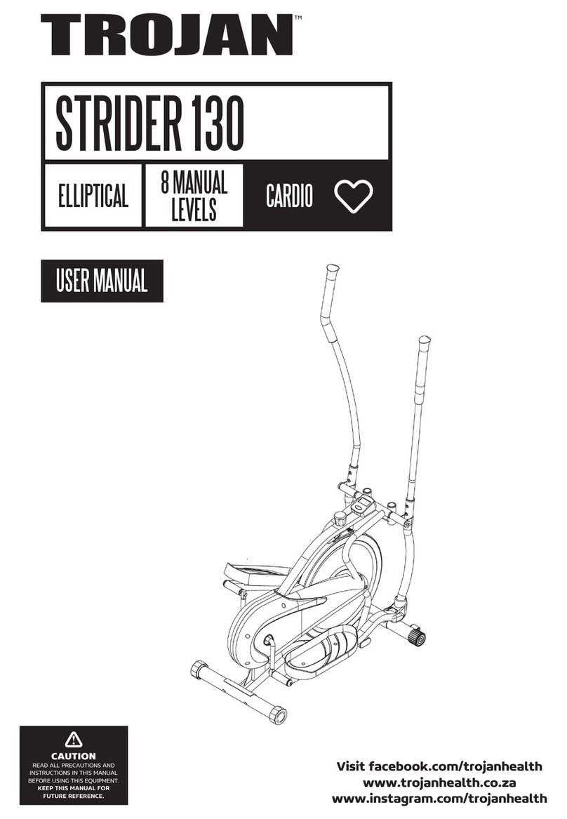
Trojan STRIDER 130 User manual
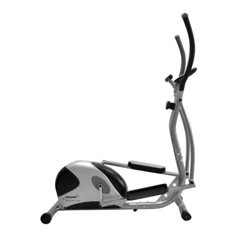
Trojan
Trojan VERTIGO 250 Installation guide
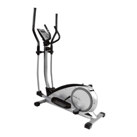
Trojan
Trojan FLUID 300 User manual
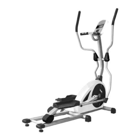
Trojan
Trojan X-CITE 450 Installation guide
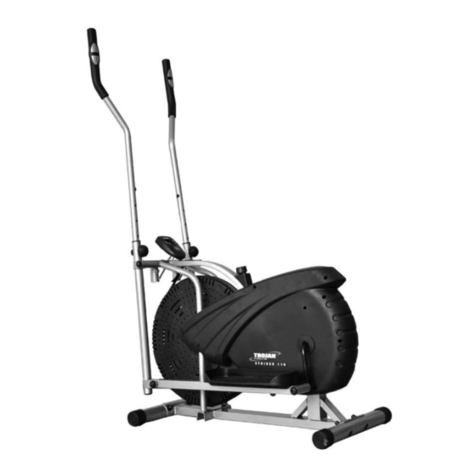
Trojan
Trojan STRIDER 110 User manual
Trojan
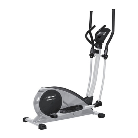
Trojan SUMMIT 280 User manual
Trojan
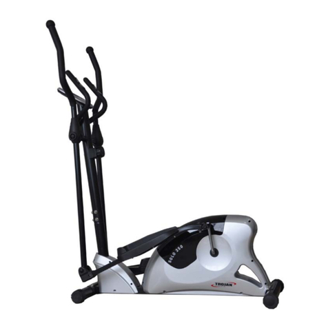
Trojan SOLO 250 Installation guide

Trojan
Trojan SUMMIT 280 User manual
Trojan
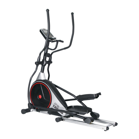
Trojan ELITE 1000 User manual
Trojan
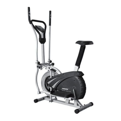
Trojan ELLIPTI-CYCLE 210 Installation guide
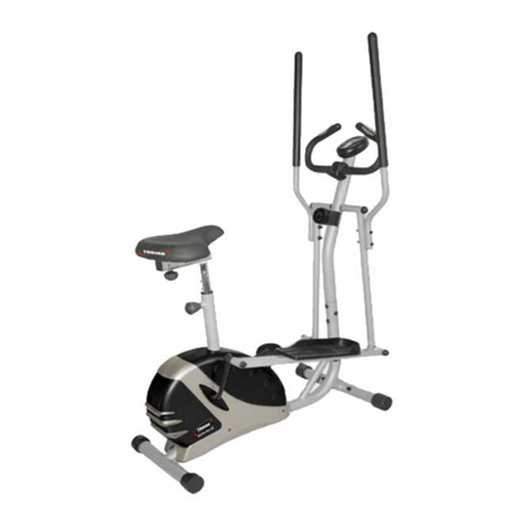
Trojan
Trojan ELLIPTI-CYCLE 200 Installation guide
Popular Elliptical Trainer manuals by other brands
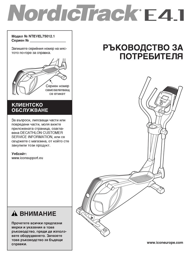
NordicTrack
NordicTrack E4.1 Elliptical null

NordicTrack
NordicTrack E4.1 Elliptical null
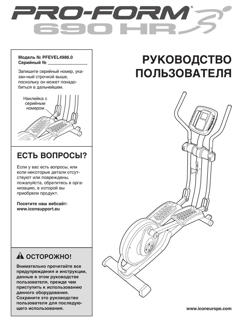
Pro-Form
Pro-Form 690 Hr Elliptical null
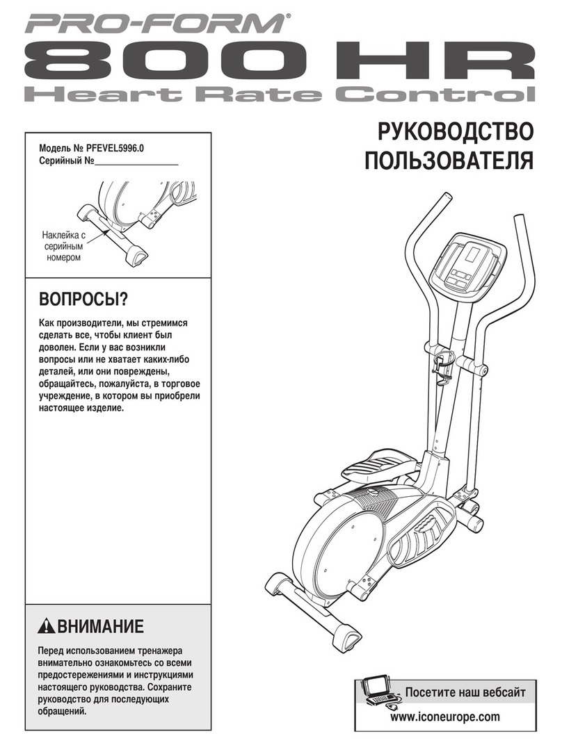
Pro-Form
Pro-Form 800 Hr Heart Rate Control Elliptical null

Weslo
Weslo Momentum 4.0 Elliptical Manuale d'istruzioni

Progear Fitness
Progear Fitness Air elliptical pro 1307 owner's manual
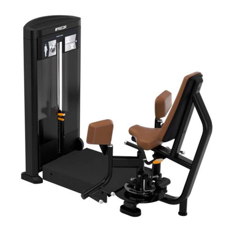
Precor
Precor Resolute RSL 620 Assembly guide
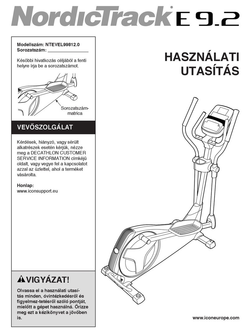
NordicTrack
NordicTrack E 9.2 Elliptical HASZNALATI UTASITAS

Vision Fitness
Vision Fitness X6600iNetTV Assembly guide

Matrix
Matrix MX-A5x owner's manual

SportsArt Fitness
SportsArt Fitness ECO-NATURAL Elite E874 owner's manual

Sears
Sears FREE SPIRIT C249 30737 0 owner's manual
