Trotec DS 30 User manual

TRT-BA-DS30-DS60-TC2016-24-003-EN
DS 30 / DS 60
EN
ORIGINAL INSTRUCTIONS
POOL DEHUMIDIFIER

2 EN
pool dehumidifier DS 30 / DS 60
Table of contents
Notes regarding the instructions ..........................................2
Safety .....................................................................................2
Information about the device................................................4
Transport and storage...........................................................6
Assembly and installation.....................................................6
Operation .............................................................................10
Errors and faults..................................................................12
Maintenance ........................................................................13
Technical annex...................................................................16
Disposal ...............................................................................23
Declaration of conformity ...................................................23
Notes regarding the instructions
Symbols
Warning of electrical voltage
This symbol indicates dangers to the life and health of
persons due to electrical voltage.
Warning
This signal word indicates a hazard with an average
risk level which, if not avoided, can result in serious
injury or death.
Caution
This signal word indicates a hazard with a low risk
level which, if not avoided, can result in minor or
moderate injury.
Note
This signal word indicates important information
(e.g. material damage), but does not indicate hazards.
Info
Information marked with this symbol helps you to carry
out your tasks quickly and safely.
Follow the manual
Information marked with this symbol indicates that the
instructions must be observed.
You can download the current version of the instructions and
the EUdeclaration of conformity via the following link:
DS 30
https://hub.trotec.com/?id=39576
DS 60
https://hub.trotec.com/?id=39581
Safety
Read this manual carefully before starting or using the
device. Always store the manual in the immediate vicinity
of the device or its site of use!
Warning
Read all safety warnings and all instructions.
Failure to follow the warnings and instructions may
result in electric shock, fire and/ or serious injury.
Save all warnings and instructions for future
reference.
This appliance can be used by children aged from
8years and above and persons with reduced physical,
sensory or mental capabilities or lack of experience
and knowledge if they have been given supervision or
instruction concerning use of the appliance in a safe
way and understand the hazards involved.
Children shall not play with the appliance. Cleaning and
user maintenance shall not be made by children
without supervision.
• Do not use the device in potentially explosive rooms.
• Do not use the device in aggressive atmosphere.
• Let the device dry out after a wet clean. Do not operate it
when wet.
• Do not use the device with wet or damp hands.
• Do not expose the device to directly squirting water.
• Never insert any objects or limbs into the device.
• Do not cover or transport the device during operation.
• Do not sit on the device.
• This appliance is not a toy! Keep away from children and
animals. Do not leave the device unattended during
operation.

EN 3
pool dehumidifier DS 30 / DS 60
• Check accessories and connection parts for possible
damage prior to every use of the device. Do not use any
defective devices or device parts.
• Ensure that all electric cables outside of the device are
protected from damage (e.g. caused by animals). Never
use the device if electric cables or the power connection
are damaged!
• The electrical connection must correspond to the
specifications in chapter Technical data.
• Insert the mains plug into a properly secured mains
socket.
• Observe the device's power input, cable length and
intended use when selecting extensions to the power
cable. Completely unroll extension cables. Avoid electrical
overload.
• Before carrying out maintenance, care or repair work on
the device, remove the mains plug from the mains socket.
Hold onto the mains plug while doing so.
• Disconnect the power cable from the mains socket when
the device is not in use.
• Do not under any circumstances use the device if you
detect damages on the mains plug or power cable.
If the supply cord is damaged, it must be replaced by the
manufacturer, its service agent or similarly qualified
persons in order to avoid a hazard.
Defective power cables pose a serious health risk!
• Observe the storage and operating conditions as given in
the Technical data chapter.
• Only install the device in compliance with the national
installation regulations.
• Make sure that the air inlet and outlet are not obstructed.
• Make sure that the suction side is kept free of dirt and
loose objects.
• Do not remove any safety signs, stickers or labels from the
device. Keep all safety signs, stickers and labels in legible
condition.
• Only transport the device in an upright position with an
emptied condensation tank or drain hose.
• Discharge the collected condensate before transport and
storage. Do not drink it. Health hazard!
Intended use
Only use the device as a stationary dehumidifier for drying and
dehumidifying room air whilst adhering to the technical data
and safety instructions.
Intended use comprises:
• drying and dehumidifying:
– indoor swimming pools
– whirlpool rooms
– wellness areas
– therapy pools
– thermal baths
A sufficient fresh air supply must be ensured at the installation
site of the device.
Improper use
• Do not place the device on wet or flooded ground.
• Do not place any objects, e.g. clothing, on the device.
• Do not use the device outdoors.
• Any unauthorised modifications, alterations or structural
changes to the device are forbidden.
• Any operation other than as described in this manual is
prohibited. Non-observance renders all claims for liability
and guarantee null and void.
Personnel qualifications
People who use this device must:
• be aware of the dangers that occur when working with
electric devices in damp areas.
• have read and understood the instructions, especially the
Safety chapter.
Maintenance tasks which require the housing to be opened
must only be carried out by specialist companies for cooling and
air-conditioning or by Trotec.

4 EN
pool dehumidifier DS 30 / DS 60
Residual risks
Warning of electrical voltage
Work on the electrical components must only be
carried out by an authorised specialist company!
Warning of electrical voltage
Before any work on the device, remove the mains plug
from the mains socket!
Hold onto the mains plug while pulling the power cable
out of the mains socket.
Warning
Dangers can occur at the device when it is used by
untrained people in an unprofessional or improper way!
Observe the personnel qualifications!
Warning
A falling device can cause injuries! Always transport
and assemble the device with the help of other
persons. Never stand below the device when it is
suspended. Ensure adequate stability of the device's
wall fixing.
Warning
The device is not a toy and does not belong in the
hands of children.
Warning
Risk of suffocation!
Do not leave the packaging lying around. Children may
use it as a dangerous toy.
Behaviour in the event of an emergency
1. In an emergency, disconnect the device from the mains
feed-in: Hold onto the mains plug while pulling the power
cable out of the mains socket.
2. Do not reconnect a defective device to the mains.
Information about the device
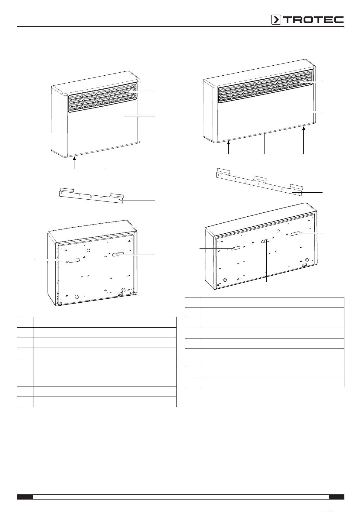
Description of the device
The pool dehumidifiers of the DSseries maintain a constant
humidity level around the clock.
The humidity is automatically regulated to an ideal level that
reliably prevents corrosion, condensation and mould formation.
The pool dehumidifiers of the DSseries use the principle of
condensation to automatically dehumidify rooms.
The fan sucks damp room air through the air inlet, the
evaporator and the condenser located behind it. The air is
cooled at the cold evaporator until it is below the dew point.
Water vapour contained in the room air precipitates on the
evaporator fins as condensation or rime. The dehumidified,
cooled air is rewarmed at the condenser and blown out at a
temperature of approx. 5°C above room temperature.
The drier air, thus conditioned, mixes with the air in the room
via the air outlet. The humidity in the room where the device is
positioned is reduced as air constantly circulates through the
device. Depending on the air temperature and the relative
humidity, the condensed water either drops continuously or only
during the defrost phase through the pre-assembled
condensation drain hose and is discharged from the device.
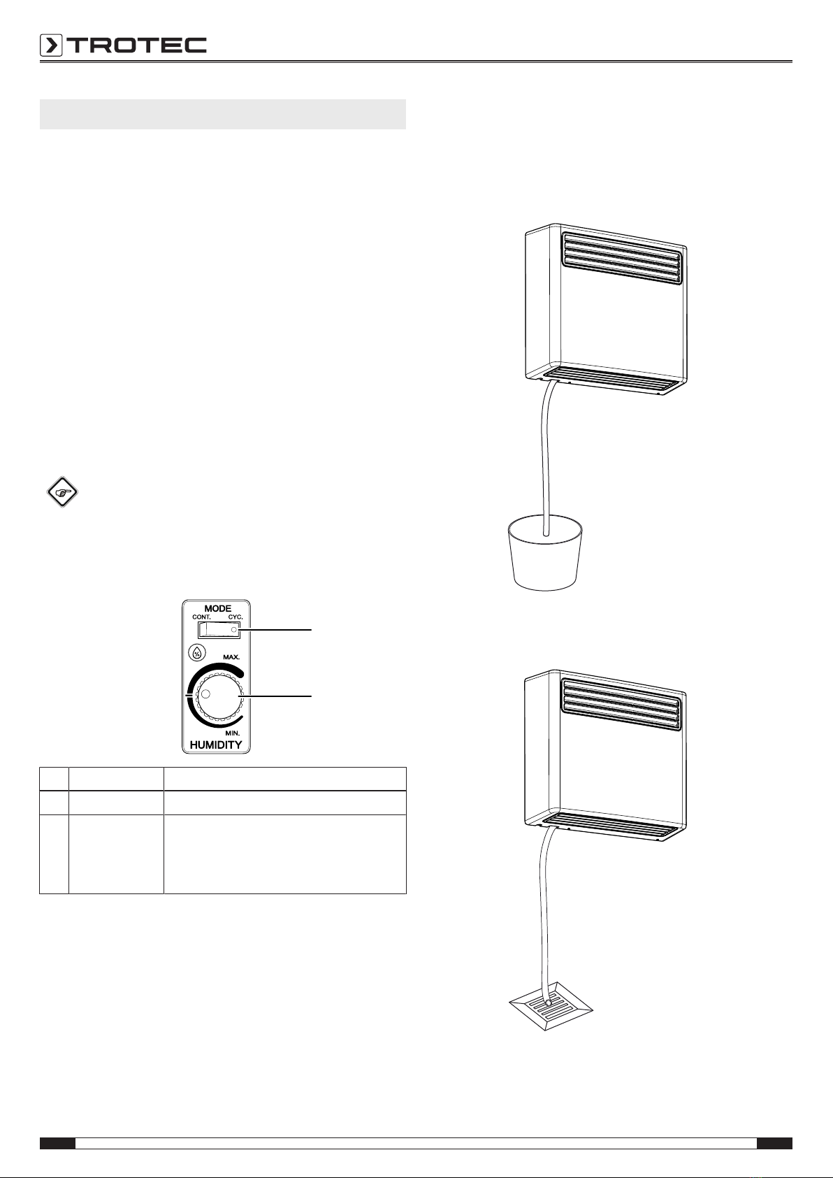
To set the desired humidity level, a hygrostat with control dial is
provided in the device's interior.
The device can reduce the relative humidity of a room to approx.
30%.
At a room temperature of 15°C, the devices emit 1.6 to 3times
of their power consumption to the room air in form of heat (see
chapter Technical data, COP). Because of the heat dissipation,
which develops during operation, the room temperature can
therefore rise by approx. 1 to 3°C.
We recommend a humidity level of approx. 55%. At this level
most people perceive the climate in pool and wellness areas as
agreeable.
In public swimming pools a fresh air supply is officially required,
please observe the respective legal standards and regulations.
Fresh air may be supplied from outside by discharging the room
air to the outside using a fan. This generates a slight negative
pressure in the room. The vacuum leads to dry air streaming out
of the surrounding areas/ fresh air flowing into the room from
outside. The dry air reduces the dehumidification demand and
the fresh air increases the climate comfort in the room.
Note
If your swimming pool is filled with thermal water,
a fresh air supply amounting to 10% of the air
volume is absolutely imperative in order to avoid
damage to the dehumidifier.

EN 5
pool dehumidifier DS 30 / DS 60
Device depiction
DS30
1
2
4
6
3
5, 7
6
No. Designation
1 Air outlet
2 Housing
3 Air inlet
4 Wall holder
5 Connection for condensation drain hose
(inside the device)
6 Suspension
7 Control dial (tamper-proof installation inside the device)
DS60
1
2
6
3 75
6
6
4
No. Designation
1 Air outlet
2 Housing
3 Air inlet
4 Wall holder
5 Connection for condensation drain hose
(inside the device)
6 Suspension
7 Control dial (tamper-proof installation inside the device)

6 EN
pool dehumidifier DS 30 / DS 60
Transport and storage
Note
If you store or transport the device improperly, the
device may be damaged.
Note the information regarding transport and storage of
the device.
Transport
Always utilize the help of another person to transport and
assemble the DS 30. Always utilize the help of two other
persons to transport and assemble the DS 60. Do not try to
transport or assemble the device without the help of another
person. To lift the device, use a forklift or an elevating truck as
appropriate.
Before transporting the device, observe the following:
• Hold onto the mains plug while pulling the power cable out
of the mains socket.
• Do not use the power cable to drag the device.
• Drain the remaining condensate from the device.
After transporting the device, observe the following:
• Set up the device in an upright position after transport.
• After having transported the device in horizontal position,
leave the device to rest for 12to24hours, so the
refrigerant can accumulate within the compressor. Wait
12to24hours before switching the device back on! Acting
contrary might lead to compressor damage and a
malfunctioning device. Any warranty claims will be voided
in this case.
Storage
Before storing the device, proceed as follows:
• Drain the remaining condensate from the device.
• Empty and clean the condensation tank and the
condensation drain hose prior to storage.
• Hold onto the mains plug while pulling the power cable out
of the mains socket.
When the device is not being used, observe the following
storage conditions:
• dry and protected from frost and heat
• in an upright position where it is protected from dust and
direct sunlight
• with a cover to protect it from invasive dust, if necessary
• Place no further devices or objects on top of the device to
prevent it from being damaged.
Assembly and installation
Scope of delivery
• 1x Device
• 1x Wall holder
• 1x Condensation drain hose, outer diameter: 12mm,
length: 400mm
• 1x Manual
Unpacking the device
1. Open the cardboard box and take the device out.
2. Completely remove the packaging.
3. Fully unwind the power cable. Make sure that the power
cable is not damaged and that you do not damage it during
unwinding.
Assembly
Always utilize the help of another person to transport and
assemble the DS 30. Always utilize the help of two other
persons to transport and assemble the DS 60. Do not try to
transport or assemble the device without the help of another
person. To lift the device, use a forklift or an elevating truck as
appropriate.
Observe the following instructions:
• When assembling the device, keep a sufficient distance to
heat sources.
• When assembling the device, especially in wet areas,
secure the device locally with an RCD (Residual Current
protective Device) which complies with the relevant
regulations.
• Make sure that extension cables are unrolled completely.
• Insert the mains plug into a properly secured mains
socket.
• When assembling the device, observe the minimum
distance from adjacent walls or other objects as described
in the Technical Data chapter.
C
C
A
BD

EN 7
pool dehumidifier DS 30 / DS 60
Installation instructions
1,25 - 2 m
2 - 3,5 m
Pool
The device must be equipped with an RCD (residual current protective device) and
installed at a height of at least 300mm above the ground(*2).
The device may be installed
at a distance of 1.25m from
the pool. The installation
height must be 2.5m above
the pool surface(*1, *2).
The device must be
equipped with an RCD
(residual current protective
device). The installation
height may be chosen
freely(*2).
*1: The use of a residual current protective device is not mandatory, but
recommended for all devices. Nominal current= 30mA.
*2: The circuit breaker for the device must correspond to the IPXregulations.
2,5m
Pool
The device must be
accessible for maintenance.
If the device is installed at a
distance of less than 1.25m
from the pool, the
installation height must be at
least 2.5m above the pool
surface.

8 EN
pool dehumidifier DS 30 / DS 60
Assemble the device as follows:
Select screw and wall plug sizes suitable for the weight of the
device (see technical data) and the structure of the wall.
1. The table or floor on which you should now unpack the
device must be clean.
2. Open the screw connection at the housing.
DS 30
DS 60
Info
The principle of hanging up the DS60 is the same as
for the DS30. But the DS60 comes with a longer
suspension rail. The following steps will be illustrated
by using the DS30 as example.
3. Remove the housing.
4. Mark the position for the bore holes.
5. Drill the holes into the wall.
6. Insert suitable wall plugs into the drill holes.
7. Fasten the wall holder in place.

EN 9
pool dehumidifier DS 30 / DS 60
8. Suspend the device from the wall holder by means of the
mounting brackets. Utilize the help of one or two other
persons as well as suitable lifting gear to do so.
9. Check whether the condensation drain hose is positioned
correctly. The condensation drain hose must not be
kinked.
DS 30
7
DS 60
7
10. Use the MODEbutton(8) to select the desired operating
mode (see chapter Setting the operating mode).
11. Set the control dial(7) to the desired humidity level (see
chapter Regulating the room humidity level).
12. Put the housing back on the device.
13. Fasten the housing to the device.
Connecting the power cable
• Insert the mains plug into a properly secured mains
socket.

10 EN
pool dehumidifier DS 30 / DS 60
Operation
• Once the device has been switched on, the drying function
works fully automatically.
• To make sure that the built-in sensor can determine the
humidity correctly and that the room air is permanently
filtered, the fan continues to operate until the device is
switched off.
• Avoid open doors and windows.
Notes regarding the dehumidification performance
The dehumidification performance depends on:
• the layout of the room
• the room temperature
• the relative humidity
The higher the room temperature and relative humidity, the
greater the dehumidification performance.
Operating elements
Info
You can access the operating elements by removing
the housing, see chapter Assembly.
The control panel of the DS30 is located on the
left-hand side, in case of the DS60 it can be found on
the right.
7
8
No. Designation Meaning
7 Control dial For setting the desired humidity level
8MODEbutton For setting the desired operating mode:
CONT. = fan runs permanently.
CYC. = fan switches on and off along
with the compressor.
Positioning the condensation drain hose
The condensation drain hose is already installed when the
device is delivered.
1. Ensure that the condensation drain hose is properly
connected to the device and is free of damage.
2. Depending on the application, position the end of the
condensation drain hose as follows:
ðPlace a sufficiently dimensioned container (DS30: at
least 50litres; DS60: at least 90litres) beside the
device and insert the hose end. Check the filling level of
the container regularly.
ðPosition the end of the condensation drain hose near a
water drain. For larger distances, a longer hose of the
same type can also be used.
3. Regularly check the condensation drain hose for
obstructions or kinks.
You can connect an extension as needed.

EN 11
pool dehumidifier DS 30 / DS 60
External condensate pump (optional)
The device can optionally be operated with an external
condensate pump.
It can be obtained from Trotec as article number
6.100.000.019.
Switching the device on
1. Ensure that the condensation drain hose has been laid and
connected properly. Do not create tripping hazards.
2. Ensure that the condensation drain hose is not bent or
jammed and that there are no objects on the condensation
drain hose.
3. Ensure that the condensation can run off properly.
4. Insert the mains plug into a properly secured mains
socket.
Setting the operating mode
In CYCLEmode (CYC.) the fan switches off along with the
compressor when the desired humidity level is reached.
In CONTINUOUS operation (CONT.) the fan keeps running
continuously and so permanently circulates the air.
This makes the humidity measurement more accurate or faster.
Regulating the room humidity level
Info
You can access the operating elements by removing
the housing, see chapter Assembly.
The control panel of the DS30 is located on the
left-hand side, in case of the DS60 it can be found on
the right.
1. Set the desired humidity level via the control dial(7).
2. Turn the control dial to the line marking the 9o'clock
position. After 2days a humidity level between 50 and
55% should be reached.
3. Then check the humidity level by means of a
thermohygrometer. If the air is too dry (insufficient
humidity level), turn the hygrostat control approx. 1cm to
the left (counter-clockwise), if the air is too humid
(excessive humidity), turn it approx. 1cm to the right
(clockwise).
7
4. Every time you have changed the hygrostat setting wait for
2days, then repeat the procedure until the desired
humidity level is reached.
ðUpon reaching the desired humidity value, the compressor
switches off automatically.
ðIf the set humidity level is exceeded, the compressor will
switch back on to dehumidify the room air once again.
Automatic defrost
If the room temperature is lower than 15°C, the heat exchanger
will freeze during dehumidification. The device will then carry
out an automatic defrost. The duration of the defrost process
can vary depending on the room temperature. The lower the
temperatures, the longer the defrost period.
Dehumidification in the swimming pool
Indoor swimming pools and wellness areas offer a marvellous
recreational and training environment, but the evaporation at the
water surface poses a serious problem for the building
structure. A prolonged influence of high humidity levels rapidly
leads to the deterioration of both the building and the furniture.
Condensation in wellness area and indoor swimming pool
If this problem is ignored, condensed water can turn into a
nightmare for an indoor swimming pool or wellness area. The
evaporation at the water surface distinctly increases the
moisture content of the air. Admittedly, the higher the humidity,
the lower the evaporation at the water surface. But the high
humidity level is also the basis for mould; and it can cause
damage to the building stock – right up to its falling into ruins.
Consequences of uncontrolled humidity are:
• corrosion
• damage to the building stock
• a disagreeable room climate
• condensate formation
• steam
• mould and stains
• misting
In the past, the air was discharged by use of a ventilation
system spending an unreasonable amount of energy to reduce
the condensation in the swimming pool. Modern drying
technology sees to new and more energy-efficient options.

12 EN
pool dehumidifier DS 30 / DS 60
Fresh air supply
In public swimming pools a fresh air supply is officially required,
please observe the respective legal standards and regulations.
Fresh air may be supplied from outside by discharging the room
air to the outside using a fan. This generates a slight negative
pressure in the room. The vacuum leads to dry air streaming out
of the surrounding areas/ fresh air flowing into the room from
outside. The dry air reduces the dehumidification demand and
the fresh air increases the climate comfort in the room.
Note
If your swimming pool is filled with thermal water,
a fresh air supply amounting to 10% of the air
volume is absolutely imperative in order to avoid
damage to the dehumidifier.
Cost effectiveness
As standard the dehumidifiers of the DS series come equipped
with internal heat recovery, thus automatically utilizing the
released process heat for low-cost heating of the room air.
a
e
b
c
d
f
a condensate discharge d warm, damp air
b floor level e warm, dry air
c pool water f pool dehumidifier
DSseries
Shutdown
Warning of electrical voltage
Do not touch the mains plug with wet or damp hands.
• Hold onto the mains plug while pulling the power cable out
of the mains socket.
• Clean the device according to the Maintenance chapter.
• Store the device according to the Storage chapter.
Errors and faults
The device has been checked for proper functioning several
times during production. If malfunctions occur nonetheless,
check the device according to the following list.
The device does not start:
• Check the power connection.
• Check the power cable for damages.
• Check the on-site fusing.
• Have the electrics checked by a specialist company for
cooling and air-conditioning or by Trotec.
The device is running, but there is no formation of
condensate:
• Check whether the condensation drain hose is positioned
correctly.
• Check the room temperature. Observe the device's
permissible operating range according to the technical
data.
• Ensure that the relative humidity complies with the
technical data.
• Check the preselected humidity level at the hygrostat's
control dial(7). The humidity in the room must be above
the selected range. Reduce the desired humidity level by
turning the control dial(7) to the right (clockwise).
The device is loud or vibrates:
• Check whether the device is mounted horizontally.
• Check the inside of the device for dirt. Clean the interior of
the device if necessary.
The device gets very warm, is loud or loses power:
• Check the air inlets for dirt. Remove external dirt.
• Check the inside of the device for dirt. Clean the interior of
the device if necessary.
Your device still does not operate correctly after these
checks?
Please contact the customer service. If necessary, bring the
device to a specialist company for cooling and air-conditioning
or to Trotec for repair.

EN 13
pool dehumidifier DS 30 / DS 60
Maintenance Maintenance intervals
Maintenance and care interval before every
start-up
as needed at least every
2weeks
at least every
4weeks
at least every
6months
at least
annually
Check air inlets and outlets for dirt
and foreign objects and clean
ifnecessary
X X
Clean the exterior X X
Visually check the inside of the
device for dirt
X X
Check for damage X X
Check the attachment screws X X
Test run X
Empty the optional condensate
pump, condensation tray and/or
condenser dryer
X
Maintenance and care log
Device type: ............................................. Device number: ....................................
Maintenance and care interval 1 2 3 4 5 6 7 8 9 10 11 12 13 14 15 16
Check air inlets and outlets for dirt
and foreign objects and clean
if necessary
Clean the exterior
Visually check the inside of the
device for dirt
Check for damage
Check the attachment screws
Check the optional condensate
pump and tank, and clean
if necessary
Test run
Comments
1. Date: ...................................
Signature: ................................
2. Date: ....................................
Signature: .................................
3. Date: ....................................
Signature: .................................
4. Date: ....................................
Signature: .................................
5. Date: ...................................
Signature: ................................
6. Date: ....................................
Signature: .................................
7. Date: ....................................
Signature: .................................
8. Date: ....................................
Signature: .................................
9. Date: ...................................
Signature: ................................
10. Date: ..................................
Signature: .................................
11. Date: ..................................
Signature: .................................
12. Date: ..................................
Signature: .................................
13. Date: .................................
Signature: ................................
14. Date: ..................................
Signature: .................................
15. Date: ..................................
Signature: .................................
16. Date: ..................................
Signature: .................................

14 EN
pool dehumidifier DS 30 / DS 60
Activities required before starting maintenance
Warning of electrical voltage
Do not touch the mains plug with wet or damp hands.
• Hold onto the mains plug while pulling the power cable out
of the mains socket.
Warning of electrical voltage
Maintenance tasks at the electrical equipment or the
air-conditioning technology must only be carried out by
specialist companies for cooling and air-conditioning or
by Trotec.
Cleaning the housing
Clean the housing with a soft, damp and lint-free cloth. Ensure
that no moisture enters the housing. Protect electrical
components from moisture. Do not use any aggressive cleaning
agents such as cleaning sprays, solvents, alcohol-based or
abrasive cleaners to dampen the cloth.
Cleaning the inside of the device
Pool dehumidifiers of the DSseries are specifically designed for
the surrounding conditions in indoor swimming pools. The used
materials are resistant to air containing salt or chlorine.
Nonetheless, inspect the condition of the device interior at
regular intervals. Excessive concentrations of chlorine or salt
can affect the internal components. For this reason, check the
device interior at least once per year.
1. Open the screw connection at the housing.
DS 30
DS 60
2. Remove the housing.
3. Remove heavy soiling on the inside of the device.
If necessary, clean the interior of the device using
compressed air or lukewarm soapsuds.

EN 15
pool dehumidifier DS 30 / DS 60
4. Put the housing back on the device.
5. Fasten the housing to the device.
6. Plug the power cable back into the mains socket.
Refrigerant circuit
• The entire refrigerant circuit is a maintenance-free,
hermetically sealed system and may only be maintained or
repaired by specialist companies for cooling and
air-conditioning or by Trotec.

16 EN
pool dehumidifier DS 30 / DS 60
Technical annex Technical data
Parameter Value
Model DS30 DS60
Dehumidification performance see dehumidification diagrams
Power supply 1/N/PE~ 230V/ 50Hz
Power cable CEE7/7 / l= 3.5m
Protection class IP23
Power input dehumidification 0.75kW 1.2kW
Power input ventilation 88W 85W
Nominal/peak current 4.4A/ 15.8A 7.5A/ 30A
Heat emission at 15°C 1.35kW 2.3kW
Coefficient of performance (COP *) 2.5 2.9
Refrigerant R-407C R-407C
Amount of refrigerant 500g 800g
GWP (Global Warming Potential) 1,774 1,774
CO2 equivalent 0.887t 1.419t
Air volume (freely blowing) 700m³/h 1,280m³/h
Sound pressure level at a distance of3m 52 dB(A) 54 dB(A)
Operating range temperature 0to 40°C 0to 40°C
Setting range relative humidity 30% to 60%RH
Max. permissible relative humidity 90%RH
Condensation drain hose ø12mm (inside), l= 40cm
Weight 39kg 60kg
Dimensions (widthx depthx height)
incl. wall holder
787x 280x 690mm 1,255x 280x 690mm
Standard faceplate plastic
Minimum distance to walls or other objects:
A: top:
B: bottom:
C: side:
D: front:
20 cm
20cm (see installation instructions)
20cm
20cm
20cm
20cm (see installation instructions)
20 cm
20cm
* The COP is the ratio of the generated cooling capacity or heat output to the electrical power input.
Dehumidification chart
l / 24 h
35
30
25
20
15
10
°C
1) 2)
40 % 50 %
30 %
60 % 70 %
80 %
0 10 20 30 40 50 60
2,15
1,90
1,70
1,50
1,35
1,20
0,80
0,75
0,70
0,65
0,60
0,55
DH 30 VPR
DS 30
l / 24 h
35
30
25
20
15
10
°C
1) 2)
40 % 50 %
30 %
60 % 70 %
80 %
0 20 40 60 80 100 120
4,1
3,5
3,1
2,6
2,3
1,9
1,3
1,2
1,1
1,0
0,9
0,8
DH 60 VPR
DS 60
No. Designation
1) Heat emission in kW at 60%RH
2) Power input in kW at 60%RH

EN 17
pool dehumidifier DS 30 / DS 60
Refrigerant circuit diagram DS30/ DS60
COMPRESSOR
SOLENOID VALVE
AIR CONDENSER
EVAPORATOR
DRIER
CAPILLARY
INSULATION
PROCESS PORT

18 EN
pool dehumidifier DS 30 / DS 60
Wiring diagram DS30/ DS60
L Linie / Außenleiter M1 Compressor / Kompressor
N Common line / Gemeinsame M2 Fan motor / Lüftermotor
E Earthing / Erdung Y Two way valve / Abtau-Magnetventil
TS Terminal Strip / Euro-Klemmleisten S1 Fan mode switch / Gebläsemodusschalter

EN 19
pool dehumidifier DS 30 / DS 60
Exploded assembly drawing DS30 Info
The position numbers of the spare parts differ from
those describing the positions of the components
mentioned in these instructions.
2 1315 16 1042
36
1
33
26 31 832
14
5
34
9 12
27282930
18
6
22
19
20
7
4
3
35
37
38
39 11
25
23
24
17
40
21
41
Replacement cover DS30
P10006263

20 EN
pool dehumidifier DS 30 / DS 60
Spare parts list DS30
NO. SPARE PART QTY. NO. SPARE PART QTY.
1 Strucktural back 1 22 Terminal strip 1
2 Condensing coil base plate 1 23 Electronic controller 1
3 Right side panel 1 24 PCB spacer 4
4 Left side panel 1 25 Humidistat venting hose 1
5 Compressor base plate 1 26 Water pan 1
6 Control cover 1 27 Nut for hose fitting 1
7 Dashboard 1 28 Sealing washer 1
8 Bottom housing profile 1 29 Hose fitting 1
9 Compressor cover 1 30 Hosing 1
10 Condensing coil insulating profile 1 31 Evaporating coil 1
11 Wall bracket 1 32 Drops tray 1
12 Compressor 1 33 Edge profile 2
13 Condensing coil 1 34 Defrost valve coil 1
14 Fan 1 35 Defrost valve 1
15 Low pressure switch 1 36 Cable tie mount 8
16 High pressure switch 1 37 Adjustable wall spacer 2
17 Humidistat 1 38 Insulating foam 1
18 Humidistat knob 1 39 Acoustic insulating foam 1
19 Fan mode switch 1 40 Cable gland 1
20 Cable clamp 1 41 Power supply cover 1
21 Pipe clip 1 42 Copper tube bracket 2
This manual suits for next models
1
Table of contents
Other Trotec Dehumidifier manuals

Trotec
Trotec 1120001110 User manual

Trotec
Trotec TTK 500 User manual

Trotec
Trotec TTR 5200 User manual

Trotec
Trotec DH 15 User manual

Trotec
Trotec TTK 400 User manual

Trotec
Trotec TTK 170 S User manual

Trotec
Trotec TTK 125 S User manual

Trotec
Trotec MD 01-10 User manual

Trotec
Trotec TTK 100 S User manual

Trotec
Trotec TTK 140 S User manual

Trotec
Trotec TTR 57 E User manual

Trotec
Trotec TTR 200 User manual

Trotec
Trotec TTK 50 E User manual

Trotec
Trotec TTK54E User manual

Trotec
Trotec ttk 71 e User manual

Trotec
Trotec TTK 96 E User manual

Trotec
Trotec TTR 400 D User manual

Trotec
Trotec TTK 655 S User manual

Trotec
Trotec TTK 125 S User manual

Trotec
Trotec TTK 75 ECO User manual