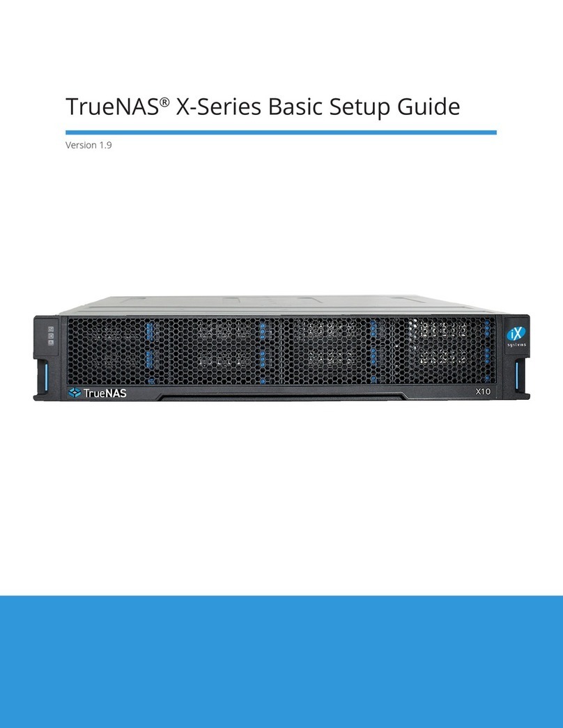
TrueNAS X-Series Manual

TrueNAS® X-Series Unied Storage Array
Basic Setup Guide
Version 1.81

Copyright © 2021 iXsystems, Inc. All rights reserved. All trademarks are the property of their respective owners.
Contents
1 Unpacking the Unit ......................................................................... 1
2 Become Familiar with the X-Series System ............................................. 2
3 Rail Kit Assembly ............................................................................ 3
3.1 Rail Extenders ................................................................................... 3
3.2 Rail Spring ....................................................................................... 3
3.3 Attaching Rails to the Rack ................................................................... 4
4 Install Drive Trays ........................................................................... 5
4.1 Replacing Drives ................................................................................ 5
4.1.1 3.5” Drive Replacement ........................................................................... 6
4.1.2 2.5” Drive Replacement ........................................................................... 6
4.1.3 2.5” Read Intensive Drive Replacement ........................................................ 6
5 Connect Expansion Shelves ............................................................... 7
6 Connect Network Cables .................................................................. 7
7 Connect Power Cord ....................................................................... 7
8 Install Bezel (Optional) ..................................................................... 8
9 Controller Removal and Installation ..................................................... 8
9.1 Removing a Controller ........................................................................ 8
9.1.1 Removing a Blanking Plate ....................................................................... 9
9.2 Installing or Adding a Controller ........................................................... 10
10 Logging in to the TrueNAS Web Interface ............................................ 11
11 Direct Connections to the System Console .......................................... 11
12 Out-of-Band Management ............................................................. 12
12.1 Conguring Remote Connections ........................................................ 12
12.2 Remote Connections ....................................................................... 13
13 Additional Resources .................................................................... 14
14 Contacting iXsystems .................................................................... 14

The TrueNAS X-Series Unied Storage Array is a 2U, 12-bay, hybrid unied data storage array.
Accessory kit with 2 IEC C13 to NEMA 5-15P power
cords, 2 IEC C13 to C14 cords, and a set of velcro
cable ties.
X-Series Bezel
X-Series Unied Storage Array
Set of rackmount rails. The rails have a specic
front end, identied by a label visible on the left
above. The front ends of the rails must be in-
stalled facing the front of the rack.
A total of 12 populated or empty “air baffle” drive
trays. Trays must be installed in all bays to main-
tain proper airflow for cooling. Up to ten drive
trays are packed in a cardboard tray. Additional
drive trays are packed with the accessory kit.
Rail Extenders for racks over 30” (762mm) deep
Black USB to 3.5mm, 3.3V serial cable
1 Unpacking the Unit
TrueNAS units are carefully packed and shipped with trusted carriers. If there is any shipping damage or any
parts are missing, please take photos and contact iXsystems support immediately at [email protected],
1-855-GREP4-iX (1-855-473-7449), or 1-408-943-4100.
Please locate and record the hardware “A1-”serial numbers on the back of each chassis (typically on the controllers’
locking arms) for quick reference.
Carefully unpack the shipping boxes and locate these components:

2 Become Familiar with the X-Series System
The X-Series has front panel indicators for power, locate ID, and fault. The fault indicator is on during the initial pow-
er-on self-test (POST) and turns o during normal operation. It turns on if the TrueNAS software issues an alert.
The X-Series has one or two storage controllers in a side-by-side conguration.
1. Gigabit Ethernet connector 1
2. Gigabit Ethernet connector 2
3. USB device (reserved, do not remove)
4. USB 2.0 connector
5. Out-of-Band (OOB) serial port (3.5mm)
6. Out-of-Band Management Ethernet connector
7. HD mini SAS3 connectors 1 & 2
8. PCIe x8 expansion port
9. System console port (reserved)
10. MAC address label
Controller 1 Controller 2
Power Supply 1 Power Supply 2

3 Rail Kit Assembly
On racks that are 30 inches deep or less, skip to “3.2 Rail Spring”.
3.1 Rail Extenders
Racks from 31 to 36 inches deep require installation of the included rail extenders. For these deeper racks, install
cage nuts on the outside rear of the rack. The tabs on the cage nuts must be horizontal as shown.
Using the included bolts, install the rail extender inside the rear of the rack. Repeat the process for the second ex-
tender, which is a mirror image of the rst.
3.2 Rail Spring
If not already present, install a spring on the silver posts in the side of each rail.

3.3 Attaching Rails to the Rack
Chassis rails are congured to attach to round hole racks. Additional pins are included in the accessory kit to
congure the rails for square or 4mm hole racks. To reset the rails to t a square or 4mm hole rack, unscrew the
pins at each end of the rails and replace them with the correct pins.
To secure a rail to the rack, open the clamp latches on the ends of each rail. Place the rail in the rack with the front
end toward the front of the rack, aligning the pins on both ends of the rail with the mounting holes in the rack.
Swing the clamp latch closed to hold the rail in place. Use two of the supplied screws to secure the back end of the
rail in place. Repeat the process for the second rail.
Caution: Two people are required to safely lift the chassis for rack installation or removal. Do not install
drives until after the chassis has been installed in the rack, and remove all drives before removing the chassis from
the rack. Carefully place the chassis onto the rails mounted in the rack. Push the chassis in until the ears are flush
with the front of the rack. If needed, attach the bezel. Use two of the supplied screws to secure each ear to the rack.

4 Install Drive Trays
Drive trays are used to mount drives in the chassis. Each drive tray has two status LEDs. The top LED is blue when
the drive is active or a hot spare. The bottom LED changes to amber if a fault has occurred.
A tray must be placed in each drive bay to maintain proper airflow for cooling. If fewer than twelve drives are con-
nected, empty “air baffle” trays must be placed in the empty bays.
A standard drive tray installation order simplies support and is strongly recommended:
• SSD drives for write cache (W), if present
• SSD drives for read cache (R), if present
• Hard drives or SSD drives for data storage
• Air baffle ller trays to ll any remaining empty bays
Install the rst drive tray in the top left drive bay. Install the next drive tray to the right of the rst. Install remaining
drive trays to the right across the row. After a row is lled with drives, move down to the next row and start again
with the left bay.
This example shows the proper order for a write cache (W) SSD, a read cache (R) SSD, eight hard drives, and two
empty air baffle trays.
To load an individual drive tray into a bay, press the blue button to open the latch. Carefully slide the tray into a
drive bay until the left side of the latch touches the metal front edge of the chassis, then gently swing the latch
closed until it clicks into place.
TrueNAS appliances only support qualied hard drives and SSDs. Contact the Sales Team if you need more drives
or replacements. Adding unqualied drives to the system voids the warranty. Call Support if drives are improperly
installed in trays.
4.1 Replacing Drives
Depending on the conguration ordered, X-Series drive trays come preinstalled with 3.5” drives, 2.5” drives with
adapter, 2.5” read intensive (RI) drives with interposer and adapter, and/or empty air baffles that preserve system
air flow. Drives that lose functionality can be removed from the tray and a new drive installed in its place or a sys-
tem upgraded by removing the air baffles and installing new drives ordered from iXsystems.

Place the tray on a flat surface and remove the four screws holding the drive to the tray, two on each side (1). Place
the new drive in the tray with the drive connector to the rear of the tray (2), and secure the hard drive in the tray
with four screws, two on each side. (3).
4.1.1 3.5” Drive Replacement
4.1.2 2.5” Drive Replacement
4.1.3 2.5” Read Intensive Drive Replacement
Place the tray on a flat surface and remove the three screws holding the adapter to the tray, two on one side and
one on the other (1). Remove the adapter from the tray and remove the two screws that hold the 2.5” drive to the
adapter (2). Follow this process in reverse to add the new 2.5” drive to an adapter and attach to the drive tray.
Warning: the interposer is considered part of the 2.5” drive and must be removed with it. Attempting to reuse an
interposer can result in a system malfunction or data loss!
Place the tray on a flat surface and remove the three screws holding the adapter in place, two from one side and
one on the other (1). Remove the adapter from the tray and remove the three screws that hold the 2.5” drive and
interposer in place, two from the side and one underneath the adapter (2). Gently lift the 2.5” drive and interposer
free from the adapter.
When installing the new drive, follow the previous procedure in reverse, but make sure the edge of the new inter-
poser slides under the retention tab (circled) on the adapter.

5 Connect Expansion Shelves
Expansion shelves connect to the HD mini SAS3 connectors on the X-Series. For detailed connection instructions
and diagrams, refer to the Basic Setup Guide included with your iXsystems TrueNAS expansion shelf or see the on-
line SAS Connections Guide. This example shows connecting an X-Series system with an ES24F
6 Connect Network Cables
Network cables vary by conguration and are not included. Please contact iX Support with any questions.
Connect network cables to the Ethernet ports and Out-of-Band (OOB) management port before powering on and
conguring the X-Series for the the rst time.
The Out-of-Band management port on the X-Series must be connected with a shielded Ethernet cable.
7 Connect Power Cord
If any TrueNAS expansion shelves are connected to the X-Series, power on the expansion shelves and wait at least
two minutes before connecting power cables to the X-Series.
Do not plug the power cords into a power outlet yet.
Connect a power cord to the back of one power supply, pressing it into the plastic clamp and pressing on the tab to
lock it in place. Repeat the process for the second power supply and cord.
After connecting both power cords to the X-Series, plug them into power outlets. The system automatically powers
on when connected to a power outlet. This design ensures that the X-Series powers back on after a power failure.
If you want to disconnect the physical power remotely, you can connect the X-Series to a remotely-managed Power
Distribution Unit (PDU).

9 Controller Removal and Installation
Warning: To avoid the potential for data loss, iXsystems must be contacted before replacing a controller or upgrad-
ing to High Availability. See section “14 Contacting iXsystems”.
9.1 Removing a Controller
Press in the blue clip on the bottom of the controller to release the two black locking levers. Swing the locking levers
outward and pull the controller out of the system.
8 Install Bezel (Optional)
The system does not require the bezel to operate. If desired, install the bezel by screwing in the bezel posts to the
system ears. The longer posts go in the top positions on the ears. Align the bezel with the posts on the chassis ears
and press it into place. To remove, grasp the bezel from the front and pull away from the chassis.

9.1.1 Removing a Blanking Plate
If you purchased your X-Series with only one controller, you can upgrade it by adding a second controller. To re-
move the blanking plate from the empty controller slot, press in the blue clip on the bottom of the plate to release
the two black locking levers. Swing the locking levers outward and pull the blanking plate out of the system.

10 Logging in to the TrueNAS Web Interface
The IP address of the TrueNAS graphical web interface is on the TrueNAS hardware sales order or conguration
sheet. The system console also displays it after powering on (see section “11 Direct Connections to the System Con-
sole”). Please contact iX Support if the TrueNAS web interface IP address was not provided with these documents or
cannot be identied from the TrueNAS system console.
Enter the IP address into a browser on a computer on the same network to access the web interface. To log into the
TrueNAS web interface, enter the default credentials:
Username: root
Password: abcd1234
Your system is equipped with the optimal BIOS and IPMI rmware out of the box.
DO NOT UPGRADE your system’s BIOS and IPMI rmware.
11 Direct Connections to the System Console
Connect the USB end of the black cable to a computer running terminal software. Set the terminal software to:
115200 baud, 8 data bits, 1 stop bit, no parity, no ow control
The X-Series console has two modes: SES (SCSI Enclosure Services) mode, and the standard x86 console mode.
If ESM A => or ESM B => is displayed, the X-Series is in SES mode.
Switch to the X86 console mode by typing: $%^0
Press Enter twice after typing the characters. The normal x86 console is displayed.
To switch back to the SES console, type: $%^2
After logging in, the console will display the TrueNAS serial menu and boot/BIOS information.
When nished with a direct connection, be sure to remove the black 3.5mm to USB cable from the console port and
reconnect the gray cable!
The X-Series comes with a gray console port cable that connects IPMI to the console. To directly connect a system
to the X-Series Console, disconnect the gray cable from the 3.5mm console port and connect the provided black
3.5mm to USB serial cable to the port.

12 Out-of-Band Management
Out-of-Band Management (OOBM) allows you to connect to the TrueNAS hardware and make changes using the
system console. You should immediately test to conrm the OOBM Ethernet port IP address is active.
Remote support requires functioning addresses. If iXsystems precongured the system, they have set the OOBM
interfaces to the requested IP addresses. Otherwise, the OOBM IP addresses default to these static addresses:
• TrueNAS Controller 1: 192.168.100.100, subnet mask 255.255.255.0
• TrueNAS Controller 2 (if present): 192.168.100.101, subnet mask 255.255.255.0
Viewing or resetting these IP addresses to dierent values requires directly connecting to the X-Series system using
a USB-3.5mm cable and client system with a serial terminal program.
The X-Series comes with a gray console port cable that connects IPMI to the console. Ensure this cable is in place,
since Out of Band Management will not work if the cable is not properly connected.
Temporarily connect the included black USB serial cable to the 3.5mm port on the back of the TrueNAS controller.
Be sure to disconnect this cable when done!
12.1 Conguring Remote Connections
Connect the serial cable’s USB end to a computer running serial terminal software. The device name can vary by
operating system. Here are some typical examples:
• Windows: COM{4}
• macOS: /dev/tty.usbserial{xynnn}
• FreeBSD: /dev/cuaU{0}
• Linux: /dev/ttyUSB{0}
Set the terminal software to: 38400 baud, 8 data bits, 1 stop bit, no parity, no ow control
After connecting, you might need to wait for the X-Series to power up, then press Enter to display the console
menu. When prompted, use these credentials to log in to the interface:
Username / Password: sysadmin / superuser
To show the current Out-of-Band management IP address:
ifcong eth0 | grep ‘inet addr’
inet addr:10.20.1.227 Bcast:10.20.1.255 Mask:255.255.254.0
The IPMItool (https://github.com/ipmitool/ipmitool) utility must be installed on the computer connecting to the
X-Series. FreeBSD, macOS, and Linux have package systems which can be used to install IPMItool. For Windows, a
simple option is to install IPMItool through Cygwin. Only use IPMItool for remote Out-of-Band management on
the X-Series. Other IPMI utilities may not work correctly or even damage the X-Series system.

To show Out-of-Band network cong settings: ipmitool -H 127.0.0.1 -U admin -P {random} lan print
To reset the Serial Over LAN system using the Out-of-Band serial port, use the eth0 IP address.
This example uses the eth0ipaddress address: ipmitool -H eth0ipaddress -U admin bmc reset cold
Conguring Static IP Addresses
The OOBM system can be set to use a static IP address and netmask. This example shows setting the IP address to
192.168.100.100 with a netmask of 255.255.255.0, and a default gateway of 192.168.100.1:
ipmitool -H 127.0.0.1 -U admin -P {random} lan set 1 ipsrc static
ipmitool -H 127.0.0.1 -U admin -P {random} lan set 1 ipaddr 192.168.100.10
ipmitool -H 127.0.0.1 -U admin -P {random} lan set 1 netmask 255.255.255.0
ipmitool -H 127.0.0.1 -U admin -P {random} lan set 1 defgw ipaddr 192.168.100.1
Conguring DHCP IP Addresses
We do not recommend conguring the OOBM IP address with DHCP. However, you can congure the local DHCP
server to provide a xed IP address for OOBM using the MAC address. You can then nd the assigned IP address by
checking the local DHCP server logs for the MAC addresses axed to the back panel of each X-Series controller.
To congure DHCP: ipmitool -H 127.0.0.1 -U admin -P {random} lan set 1 ipsrc dhcp
Log out of the Out-of-Band management system by typing exit and pressing Enter.
The ipmitool command uses a randomized password that is unique to the X-Series system.
Replace the {random} strings in these examples with the randomized password on the sticker
placed on the back of the chassis under the Out-of-Band (OOB) serial port.
12.2 Remote Connections
A remote connection requires that the X-Series system has a shielded RJ45 cable connecting the Out-of-Band net-
working port to the local network.
In this example, 192.168.100.100 is the IP address assigned to the Out-of-Band management interface.
ipmitool -I lanplus -H 192.168.100.100 -U admin -a sol activate
SOL on another session is displayed when a Serial Over LAN connection is already in use. To reset the Serial Over
LAN system from the remote laptop or desktop computer, use:
ipmitool -H 192.168.100.100 -U admin bmc reset cold
and enter the unique randomized password.
Repeat the sol activate command above and enter the randomized password to connect to the console.
To log out of the ipmitool session, press Enter, type ~. and press Enter.

14 Contacting iXsystems
For assistance, please contact iX Support:
Contact Method Contact Options
Web https://support.ixsystems.com
Email [email protected]
Telephone Monday-Friday, 6:00AM to 6:00PM Pacic Standard
Time:
• US-only toll-free: 1-855-473-7449 option 2
• Local and international: 1-408-943-4100 option 2
Telephone Telephone After Hours (24x7 Gold Level Support only):
• US-only toll-free: 1-855-499-5131
• International: 1-408-878-3140
(International calling rates will apply)
13 Additional Resources
The TrueNAS Documentation Hub has complete software conguration and usage instructions. It is available by
clicking Guide in the TrueNAS web interface or going directly to:
https://www.truenas.com/docs/
Additional hardware guides and articles are available in the Hardware section of the Documentation Hub:
https://www.truenas.com/docs/hardware/
The TrueNAS Community forums provide an opportunity to interact with other TrueNAS users and to discuss their
congurations. The forums are available at:
https://www.truenas.com/community/
Table of contents
Other TrueNAS Storage manuals
TrueNAS
TrueNAS R20A User manual

TrueNAS
TrueNAS M Series User manual
TrueNAS
TrueNAS R Series Manual
TrueNAS
TrueNAS ES60 Manual
TrueNAS
TrueNAS R30 Manual

TrueNAS
TrueNAS ES60 Manual
TrueNAS
TrueNAS Mini 3.0 Manual
TrueNAS
TrueNAS Mini X+ Installation and operation manual

TrueNAS
TrueNAS R Series User manual
TrueNAS
TrueNAS M Series Manual

