TrueNAS M Series Manual

Version 3.4
TrueNAS®M-Series Basic Setup Guide
3rd Generation

Contents
1 Introduction ������������������������������������������������������������������������������������������������������������������������ 1
1�1 Safety �������������������������������������������������������������������������������������������������������������������������� 1
1�1�1 Static Discharge ���������������������������������������������������������������������������������������������������������������������� 1
1�1�2 Handling the System ���������������������������������������������������������������������������������������������������������������� 1
1�2 Requirements ���������������������������������������������������������������������������������������������������������������� 1
2 M-Series Components ������������������������������������������������������������������������������������������������������������ 2
2�2 Front Indicators �������������������������������������������������������������������������������������������������������������� 3
2�3 Rear Components and Ports ����������������������������������������������������������������������������������������������� 3
2�4 M-Series Expansion Slots ��������������������������������������������������������������������������������������������������� 4
3 Rack the M-Series ����������������������������������������������������������������������������������������������������������������� 5
3�1 Install Chassis Rails ���������������������������������������������������������������������������������������������������������� 5
3�2 Install Rack Rails ������������������������������������������������������������������������������������������������������������� 6
3�3 Mount the System in the Rack ��������������������������������������������������������������������������������������������� 7
4 Install Drives ����������������������������������������������������������������������������������������������������������������������� 8
5 Install Bezel (Optional) ���������������������������������������������������������������������������������������������������������� 9
6 Storage Expansion ��������������������������������������������������������������������������������������������������������������� 10
6�1 Connect SAS Cables �������������������������������������������������������������������������������������������������������� 10
6�2 Connect Expansion Shelves ����������������������������������������������������������������������������������������������� 11
7 Connect Network Cables ������������������������������������������������������������������������������������������������������� 12
7�1 Short-Reach (SR) NIC Network Setup ������������������������������������������������������������������������������������ 12
7�2 Ethernet NIC Network Setup ���������������������������������������������������������������������������������������������� 13
8 Connect Monitor and Keyboard ���������������������������������������������������������������������������������������������� 14
9 Connect Power Cables ���������������������������������������������������������������������������������������������������������� 14
10 Boot the System ���������������������������������������������������������������������������������������������������������������� 15
10�1 Connect to the TrueNAS CORE Enterprise WebUI ������������������������������������������������������������������� 15
10�2 Connect to the TrueNAS SCALE Enterprise WebUI ������������������������������������������������������������������ 15
10�3 Out-of-Band-Management ���������������������������������������������������������������������������������������������� 15
11 Additional Resources ���������������������������������������������������������������������������������������������������������� 16
12 Contacting iXsystems ��������������������������������������������������������������������������������������������������������� 16
Copyright © 2023 iXsystems, Inc. All rights reserved. All trademarks are the property of their respective owners.

Page 1
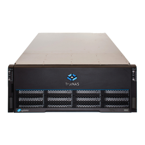
The 3rd Generation M-Series Unified Storage Array is a 4U, 24-bay, hybrid data storage array. It has redundant
power supplies and up to two TrueNAS controllers�
1 Introduction
1.1 Safety
1.2 Requirements
1.1.1 Static Discharge
1.1.2 Handling the System
We recommend these tools when installing an M-Series system in a rack:
• #2 Philips head screwdriver
• Flat head screwdriver
• Tape measure
• Level
Warning
Static electricity can build up in your body and discharge when touching conductive materials� Electrostatic
Discharge (ESD) is harmful to sensitive electronic devices and components� Keep these safety recommendations
in mind before opening the system case or handling non-hot-swappable system components�
• Turn o the system and remove power cables before opening the case or touching internal components.
• Place the system on a clean, hard work surface like a wooden tabletop. Use an ESD dissipative mat if possible to
protect the internal components�
• Touch the metal chassis with your bare hand to dissipate static electricity in your body before handling any
internal components, including components not yet installed in the system. We always recommend wearing an
anti-static wristband and using a grounding cable�
• Store all system components in anti-static bags�
Hold the system from the sides or bottom whenever possible. Always be mindful of loose cabling or connectors,
and avoid pinching or bumping these elements�
These instructions use “left” and “right” according to your perspective when facing the front of a system or rack�
Your system comes with the TrueNAS operating system preloaded�
Review the safety considerations and hardware requirements before installing an M-Series system into a rack�
Warning
The M-Series weighs 75 lbs unloaded and requires a minimum of two people to lift�
Never attempt to lift an M-Series system loaded with drives! Install the system in a rack before adding drives,
and remove drives before uninstalling the system�
When handling rails, system components, or drives, never force movement if a component seems stuck. Gently
remove the component and check for pinched cables or obstructing material before installing it again� Installing a
component with excessive force can damage the system or cause personal injury�
Note
The 3rd Generation TrueNAS M-Series systems have a unified chassis design that allows customers to upgrade
them with more powerful controllers. Customers can upgrade an M30 to an M40, an M40 to an M50, or an M50 to
an M60� Speak with an iXsystems Sales or Support Representative for more information�

Page 2
2 M-Series Components
M-Series Unified Storage Array
Set of rack-mount rails
2 IEC C13 to NEMA 5-15P power cords, 2 IEC C13
to C14 cords, and a set of cable ties
Hardware for mounting the system in a rack
DB9 to 3�5mm serial cable
Bezel
Up to 24 drive trays or air baes, depending on
the number of drives purchased with the system
TrueNAS units are carefully packed and shipped with trusted carriers to arrive in perfect condition�
If there is any shipping damage or missing parts, please take photos and contact iXsystems support immediately at
support@ixsystems�com, 1-855-GREP4-iX (1-855-473-7449), or 1-408-943-4100�
Please locate and record the hardware serial numbers on the back of each chassis for quick reference�
Carefully unpack the shipping boxes and locate these components:

Page 3
The front ears have power, locate ID, fault, and network activity indicators. The fault indicator is on during the initial
power-on self-test (POST) and turns o during normal operation. It turns on if the TrueNAS software issues an alert.
2.3 Rear Components and Ports
2.2 Front Indicators
Light / Button Color and Indication
Blue: System On
N/A: Reset Button
Blue: Locate ID Active
Red: Fault / Alert
Amber: Link Active
ID
The M-Series includes one or two TrueNAS controllers in an over-and-under configuration.
NVMe
Fan & Drives
Controller 1
Controller 2
Power Supply 1
Power Supply 2
PCIe Slots
PCIe Slots
IPMI
Ethernet
Serial Port
VGA
Port
USB 3.0
x2
USB 2.0
x2
10 Gb Ethernet
x2
IPMI
Sticker
TrueNAS
Controller
Management
Port
Serial
Number

Page 4
2.4 M-Series Expansion Slots
Expansion slots on the M-Series are reserved for specific cards or internal use:
M30 Controller Expansion Slots
M40 Controller Expansion Slots
M60 Controller Expansion Slots
M50 Controller Expansion Slots
Slot A Slot B Slot C Slot D Slot E Slot F
M30 NIC or FC N/A NTB N/A Internal
SAS Secondary NIC
M40 NIC N/A NTB External SAS Internal
SAS 4x NVME Riser, NIC2, or FC
M50 NIC1 External SAS1 NIC2 or FC External SAS2 NTB Internal SAS
M60 NIC1 External SAS1 External SAS3,
NIC2, or FC External SAS2 NTB Internal SAS

Page 5
3 Rack the M-Series
3.1 Install Chassis Rails
The M-Series requires 4U of space in an EIA-310 compliant rack that is 27” (686mm) deep, frame to frame.
The vertical rack posts must be between 26” (660�4mm) and 36” (914�4mm) apart to install the rails properly�
The chassis rails mount on each side of the system�
Place the chassis rail keyholes over the posts on the side of the chassis so the posts go through the keyholes, then
slide the rail towards the rear of the system until the metal tab clicks and secures the rail in place�
Secure the rail to the chassis using three low-profile M4 screws. Repeat this process on the other side.
Extend the inner rack rail until it locks in place (1)� Slide out the chassis rail until it stops (2)� Remove the chassis rail
by sliding the white release tab away from the inner rack rail (3), then pull the chassis rail free (4)�
M4 Screws

Page 6
Place the rail in the rack with the front end towards the front of the rack� Align the pins with the front rack mounting
holes� Push the pins into the holes until the latch clicks�
At the rear of the rail, align the pins with the rack holes. Swing the gray latch handle outwards and pull it to extend
the rail until the rail pins are fully seated in the rack holes� Release the latch to lock the rail in place�
Repeat the process for the second rack rail�
Front Rear
The rack rails install in the center of the bottom 2U of the total 4U of reserved rack space�
Unlock and retract the inner rack rail before installing it in the rack� Rotate the release lever on the back of the inner
rail as shown on the arrow label, then push the inner rail towards the back of the assembly until it stops.
3.2 Install Rack Rails
Ensure the rails are positioned in the middle of the bottom 2U of rack space� The pins that go through the rack
should be in the middle holes of each U�
3
2
1
4
3
2
1
4
Front Rear

Page 7
3.3 Mount the System in the Rack
Extend both inner rack rails out from the rack until they lock. Align the chassis rails with the rack rails, then slide the
chassis rails in until they are fully seated�
When both chassis rails are secured in the rack rails, gently push the chassis until it stops half way in.
Slide the blue release tabs on both chassis rails towards the front of the system and push the unit into the rack�
To anchor the unit in the rack, insert a long M5 screw through the retention port on each ear. The screw hole is
behind a small door on each ear�
M5
Screws
Warning
The M-Series requires two people to safely lift in and out of a rack� Do not install drives until after you mount the
M-Series in the rack� Remove all drives before taking the M-Series out of the rack�

Page 8
4 Install Drives
TrueNAS systems only support qualified HDDs and SSDs. Contact the Sales Team for more drives or replacements.
Adding unqualified drives to the system voids the warranty. Call Support if drives are improperly installed in trays.
Place a tray on a at surface. Mount a hard drive by aligning the drive connectors to the rear of the tray and pushing
the drive screw holes into the drive tray pegs�
Baes maintain proper air ow in systems with fewer than 24 drive trays. When installing a new drive, insert a at-
head screwdriver in the bae groove and gently pull to remove the bae.
Each drive bay in the chassis has two indicator lights to the right of the tray� The upper light is blue when the drive is
active or a hot spare� The lower light is solid red if a fault has occurred�
Press the silver button on the drive tray to open the latch� Carefully slide the tray into a drive bay until the right side
of the latch touches the metal front edge of the chassis, then gently swing the latch closed until it clicks into place.
We strongly recommend a standard drive tray installation order to simplify support:
• SSD drives for write cache (W), if present
• SSD drives for read cache (R), if present
• Hard drives or SSD drives for data storage
• Air bae filler trays to fill any remaining empty bays
Install the first drive in the top left bay. Install the next drive to the right of the first. Install remaining drives to the
right across the row. After a row is filled, move down to the next row and start again with the left bay.

Page 9
5 Install Bezel (Optional)
Slide the right side of the bezel into the attachment points on the right ear, then push the left side of the bezel into
the left ear latch until it locks�
To remove the bezel, push the left ear release tab away from the bezel, then swing the bezel out.

Page 10
6 Storage Expansion
“
C
L
I
C
K
”
Line the SAS3 cable connector up with the SAS port on the back of the system� Ensure the blue tab on the SAS cable
is facing toward the right� Gently push the connector into the port until it clicks�
6.1 Connect SAS Cables
Note
The M30 does not support storage expansion�

Page 11
To set up SAS between your TrueNAS system and expansion shelves, cable the first port on the first TrueNAS
controller to the first port on the first expansion shelf controller. High Availability (HA) systems require another
cable from the first port on the second TrueNAS controller to the first port on the second expansion shelf controller.
We do not recommend other cabling configurations. Contact iX Support if you need other cabling methods.
If your TrueNAS system has HA, reboot or failover after connecting SAS cables to sync drives between controllers.
The guide included with your Expansion Shelf has instructions for SAS connections. For more diagrams, see the
TrueNAS SAS Connections Guide (www�truenas�com/docs/hardware/expansionshelves/sasconnections)1�
The example below shows an M60 connected to two ES60s�
Important
When setting up SAS connections, please adhere to the wiring example below. Connecting expansion shelves
incorrectly causes errors. Never cable a single TrueNAS controller to dierent controllers on one expansion shelf.
6.2 Connect Expansion Shelves
1

Page 12
7 Connect Network Cables
Connect network cables from the local switch or management network to the IPMI ethernet, ixl0, and ixl1 ports on
each TrueNAS Controller� See section “2�3 Rear Components and Ports” on page 3 for port locations�
iXsystems preconfigures network ports to customer specifications before shipping.
7.1 Short-Reach (SR) NIC Network Setup
If you ordered short reach NICs with your M-Series, you can set them up now for networking.
Insert the SR optics into the first port on the NIC, then plug the SR cable into the back of the SR optics. Both the
optics and the cable will click and lock into place when installed correctly� Repeat for remaining ports�
After installing the optics and cables in the NIC connect both cables to your network switch�
SR SR4
Tip
Optics orientation can vary for dierent switches. Look at the connectors inside the ports to orient the SR optics.

Page 13
7.2 Ethernet NIC Network Setup
If you ordered four-port ethernet NICs with your M-Series, you can set them up now for networking.
Insert ethernet cables into each port on the NIC, then connect each cable to your network switch.

Page 14
9 Connect Power Cables
Do not plug the power cables into a power outlet yet. Connect a power cord to the back of one power supply�
Place the cord in the plastic clamp and press the tab into the latch to lock it in place� Repeat the process for the
second power supply and cord�
The M-Series turns on automatically when connected to power� It also turns back automatically on when power is
restored after a power failure�
8 Connect Monitor and Keyboard
We recommend connecting a monitor and keyboard for the first boot so you can configure the system and view the
initial TrueNAS web interface IP address�
Connect a keyboard and monitor to the bottom controller (Controller 1)� See section “2�3 Rear Components and
Ports” on page 3 to identify the USB and VGA ports�

Page 15
10 Boot the System
After plugging the power cables into outlets, the M-Series powers on and boots into TrueNAS.
When booted, the system console displays the TrueNAS web UI IP address. The IP address is either preconfigured
according to customer guidelines or automatically generated with DHCP� Example:
The web user interface is at:
http://192.168.100.231
https://192.168.100.231
Enter the IP address into a browser on a computer on the same network to access the web user interface�
To identify the active controller on an HA system, go to the Shell (CORE) or Linux Shell (SCALE) and enter hactl �
10.1 Connect to the TrueNAS CORE Enterprise WebUI
Out-of-band logins have separate credentials from the TrueNAS web interface� The credentials are randomized
and attached to the back of the TrueNAS chassis. For more details, see https://www�truenas�com/docs/sb-3272�
For additional details about out of band management, see the M-Series Out-of-Band-Management guide:
https://www�truenas�com/docs/hardware/mseries/mseriesoobm3�
Warning
Your system is equipped with the optimal BIOS and IPMI firmware out of the box.
DO NOT UPGRADE your system’s BIOS and IPMI firmware.
We recommend that IPMI be on a separate and secure network without Internet access�
Please contact support if you need to upgrade your system’s BIOS or IPMI firmware.
The TrueNAS CORE web interface uses default credentials for first-time logins:
Username: root
Password: abcd1234
After logging in, change the root account password in Account > Users to increase system security�
If you have more than one TrueNAS device connected to the network, mDNS can experience name conicts.
To change the hostname in the web UI, go to Network > Global Conguration > Hostname.
The TrueNAS SCALE web interface uses default credentials for first-time logins:
Username: admin
Password: abcd1234
After logging in, change the admin account password in Credentials > Local Users to increase system security�
If you have more than one TrueNAS device connected to the network, mDNS can experience name conicts.
To change the hostname in the web UI, go to Network and click Settings in the Global Conguration widget�
10.2 Connect to the TrueNAS SCALE Enterprise WebUI
10.3 Out-of-Band-Management
23

Page 16
12 Contacting iXsystems
11 Additional Resources
The TrueNAS Documentation Hub has complete software configuration and usage instructions� Click Guide in the
TrueNAS web interface or go directly to:
https://www�truenas�com/docs
Additional hardware guides and articles are in the Documentation Hub’s Hardware section:
https://www�truenas�com/docs/hardware
The TrueNAS Community forums provide opportunities to interact with other TrueNAS users and discuss their
configurations:
https://www�truenas�com/community
Having issues? Please contact iX Support to ensure a smooth resolution�
Contact Method Contact Options
Web https://support�ixsystems�com
Email support@iXsystems�com
Telephone Monday-Friday, 6:00AM to 6:00PM Pacific Standard Time:
• US-only toll-free: 1-855-473-7449 option 2
• Local and international: 1-408-943-4100 option 2
Telephone Telephone After Hours (24x7 Gold Level Support only):
• US-only toll-free: 1-855-499-5131
• International: 1-408-878-3140 (International calling rates will apply)
5
6
7
8
4567
Other manuals for M Series
4
This manual suits for next models
4
Table of contents
Other TrueNAS Storage manuals
TrueNAS
TrueNAS ES60 Manual

TrueNAS
TrueNAS ES102 Manual
TrueNAS
TrueNAS X-Series Manual

TrueNAS
TrueNAS ES60 Manual

TrueNAS
TrueNAS X Series Manual
TrueNAS
TrueNAS Mini X+ Installation and operation manual

TrueNAS
TrueNAS ES24 Manual
TrueNAS
TrueNAS ES24F Manual
TrueNAS
TrueNAS R Series User manual
TrueNAS
TrueNAS Mini R Manual
Popular Storage manuals by other brands
Compaq
Compaq StorageWorks 3000 - RAID Array release note
Spectra Logic
Spectra Logic T-Series Spectra T120 release note
IBM
IBM Ultrastar 73LZX Quick installation guide

Western Digital
Western Digital My Passport WDML2500 user manual
ECOSAFE
ECOSAFE A2T instruction manual
IOGear
IOGear Combo ION GHE835C user manual


