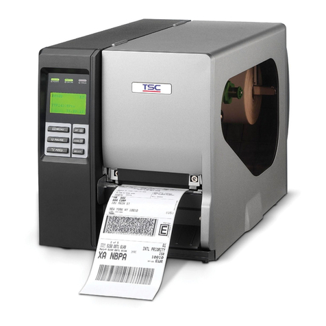
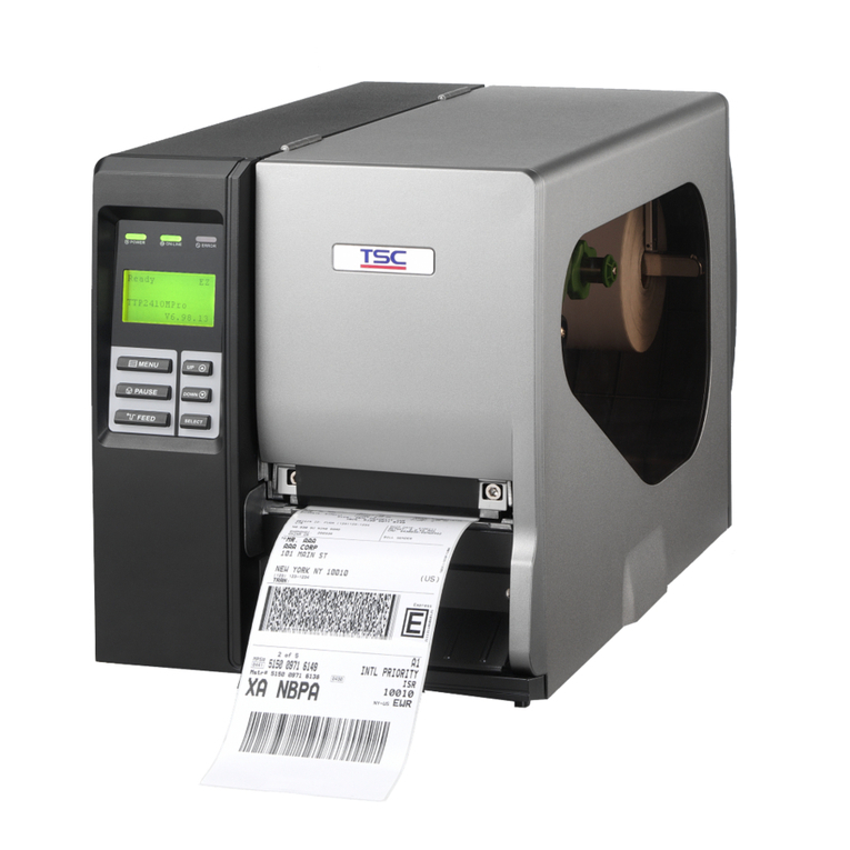
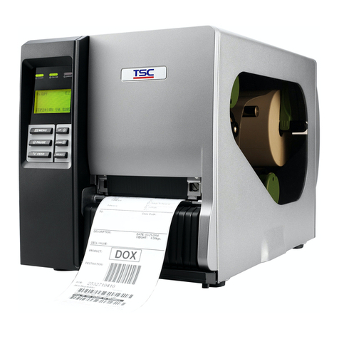
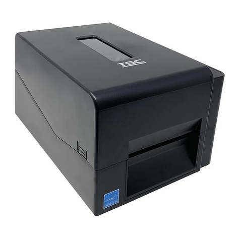
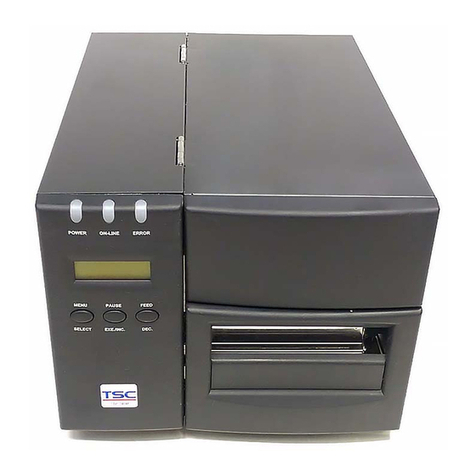
TSC TDP-643R Plus series User manual

TDP
-
643R Plus
USER’S
MANUAL
THERMAL TRANSFER / DIRECT THERMAL
BAR CODE PRINTER

Contents
Contents........................................................................................................................ii
1. PRODUCT INTRODUCTION.................................................................................... 1
1.1 Compliances .....................................................................................................2
2. Getting Started ......................................................................................................... 3
2.1 Unpacking and Inspection.................................................................................3
2.2 Equipment Checklist .........................................................................................3
2.2.1 Standard Parts........................................................................................................3
2.2.2 Optional Parts........................................................................................................3
2.3 Printer Parts......................................................................................................4
2.3.1 Top Front View......................................................................................................4
2.3.2 Rear View..............................................................................................................4
2.3.3 External Roll Mount..............................................................................................5
2.3.4 Control Panel.........................................................................................................6
3. Using the Bar Code Printer ..................................................................................... 7
3.1 Setting Up the Printer........................................................................................7
3.1.2 Setting Up the Printer............................................................................................7
3.2 Installing the Label............................................................................................7
3.3 Peel-off Function...............................................................................................9
3.4 Installing the Tag .............................................................................................10
3.5 Installing the Cutter Module............................................................................. 11
3.6 Printer Initialization..........................................................................................13
3.7 Self Test Mode and Gap Sensor Calibration ...................................................13
3.8 Dump Mode.....................................................................................................15
4. Maintenance ........................................................................................................... 16
4.1 Pre-maintenance.............................................................................................16
4.1.1 Removing the Top Cover ....................................................................................16
4.2 Removing labels stuck on the print head ........................................................17
4.3 Removing Label stuck in the Label Guides Assembly.....................................17
4.4 Troubleshooting...............................................................................................19
- 1 -
1. PRODUCT INTRODUCTION
Thank you very much for purchasing TDP-643R Plus bar code printer. The attractive
desktop printer delivers superior performance at an economical price. Both powerful
and easy-to-use, TDP-643R Plus printer is your best choice among desktop direct
thermal bar code printers.
TDP-643R Plus bar code printer offers direct thermal printing at a high speed of 3
inches per second. It can accept a wide range of media, including roll feed, die-cut,
and fan-fold labels or tags. All of the most frequently used bar code formats are
available. Fonts and bar codes can be printed in any one of four directions.
TDP-643R Plus printer provides a choice of five different sizes of alphanumeric fonts.
By using font multiplication, an even greater range of sizes is possible. Smooth fonts
can be downloaded from user friendly Windows label design software. In addition,
TDP-643R Plus is capable of independently executing BASIC programming function,
including arithmetic, logical operating, loop, flow-control and file management. This
programming capability provides greatest efficiency in label printing. The status of
printer and error messages may either be printed out or viewed on a monitor by
means of the RS-232 connection.

- 2-
1.1 Compliances
CE Class A, FCC Class A, C-Tick ClassA, TÜV/Safety, UL, CUL, BSMI, CCC

- 3-
2. Getting Started
2.1 Unpacking and Inspection
The printer has been specially packaged to withstand damage in the shipping
process. However, for fear that unexpected damage might occur, upon receiving the
bar code printer, carefully inspect the package and the device. In case of evident
damage, contact the carrier directly to specify the nature and extent of the damage.
Please retain the packaging materials in case you need to reship the printer.
2.2 Equipment Checklist
2.2.1 Standard Parts
zOne TDP-643R Plus bar code printer
zOne Windows Software/Driver CD Disk
zOne quick Start Guide
zOne power Supply
zOne power Cord
zOne Centronics Cable
zOne Label Spindle
2.2.2 Optional Parts
zExternal Roll Mount
z3” label core adapter
zGuillotine cutter module
If any parts are missing, please contact the Customer Service Department of your
purchased reseller or distributor.

- 4-
2.3 Printer Parts
2.3.1 Top Front View
Fig. 1 Printer top front view
2.3.2 Rear View
Fig.2 Printer rear view
Paper Dispense
Opening FEED Button
External Label Insert
Opening
Power Switch
Power Jack Centronics Interface
Connector Serial Port Connector

- 5-
2.3.3 External Roll Mount
Fig.3 External roll mount
Fig.4 Label spindle

- 6-
2.3.4 Control Panel
Fig. 5 Control panel
Button
FEED Button
Press the FEED button to feed the label to the beginning of the next label.
Indicators
zREADY Indicator
When the power is activated and label properly loaded, the READY indicator
will turn on.
zERROR indicator
The ERROR indicator will light on if the label is not properly loaded or when the
printer is out of labels.
ERROR Indicator
READY Indicator
FEED Button

- 7-
3. Using the Bar Code Printer
3.1 Setting Up the Printer
3.1.2 Setting Up the Printer
1. Make sure the power is off.
2. Connect the Centronics or RS-232 cable to corresponding ports or at the rear of
printer. Connect the other end of the cable to your computer.
3. Plug the power cord into the power jack at the rear of the printer, and then plug
the power cable into a properly grounded wall outlet.
3.2 Installing the Label
1. Insert the spindle into the core of the label roll.
2. With the print surface facing up, place the label roll spindle onto the slots of label
roll mount supports.
Fig. 6 Label roll and label spindle setup
3. Insert and push the label into the label insert opening until it stops.
4. Hold down the FEED button until the front edge of the label feeds about half an
inch out of the printer's label dispense opening .
Label Spindle

- 8-
Fig.7 Label installation
5. If the label is not centered within the feeding path, open the front cover by
depressing the release button on the front cover. Pull the paper release button
to the back and hold it to adjust the label position, and then release it and close
the front cover.
Fig.8 Adjust label position
6. (Manually) Rotate the label roll until it is stretches tight.
7. Press the FEED button until the READY indicator is on, and the label has been
properly installed.
Front Cover
Release Button
Paper Release Button

- 9-
3.3 Peel-off Function
In peel-off function, the printed label will be stripped from the liner paper
automatically. Follow the steps below:
1. Follow the directions in the previous section “Installing the label” to load the
label well.
2. Press the FEED button until about 3 inches of the label extends out of the label
dispense opening. Open the front cover.
3. Tear off the label from the liner paper. Place the front edge of the liner paper
between the platen and the stripping roller and push in until it stops.
4. Press the FEED button until the liner paper is out of the bottom of the stripping
roller.
5. Push the paper release button to the back and hold it to adjust the position of the
label. Rewind the label roll until the label is pulled tight between the platen and
the stripping roller. When the labels have been properly adjusted, release the
paper release button.
6. Press and release the FEED button until the front edge of next label is visible.
7. Close the front cover. The installation now is complete.

- 10 -
3.4 Installing the Tag
Note:
(1) The major difference between tag and label is that there is no adhesive liner
paper on the back of the tag.
(2) The only difference between installing tag and label is that the tag roll
unwinds from the bottom as depicted.
1. Insert the spindle into the core of the tag roll.
2. With the tag roll setting to unwind from the bottom, place the spindle onto the
slots of the external roll mount supports.
3. Push the front edge of the tag into the label insert opening until it stops.
4. Press and hold the FEED button until the front edge of tag feeds out of the
label dispense opening of the printer.
5. Open the front cover by pushing down the front cover release button, then
push the paper release button to the back and hold to adjust the tag to its
proper position.
6. Rewind the tag roll to remove any slack and adjust the paper guides until they
are close to the edges of the tag roll.
7. Press and release the FEED button until the READY indicator is on. The
installation now is complete.
Label
T
ag

- 11 -
3.5 Installing the Cutter Module
1. Open the Front Cover and remove the Top Cover.
2. Unplug the Front Cover harness from the PCB of the Button.
3. Remove the Front Cover.
4. Remove 6 screws from the button of the printer.
5. Open the Top Cover Assembly.
Screws Screws
Front Cover
Top Cover

- 12 -
6. Plug Cutter harness to the JP3 connector on the mainboard.
7. Close the Top Cover Assembly and fasten the screws.
8. Close the Top Cover.
9. Place the Cutter Module as shown in the following figure.

- 13 -
3.6 Printer Initialization
To initialize the printer, press the FEED button while turning on the printer. Instantly
the red and green indicators will flash alternately. Press the FEED button again and
the printer will be initialized.
Note: Please calibrate the gap sensor again after printer initialization is done.
3.7 Self Test Mode and Gap Sensor Calibration
To initiate the self-test mode, depress the FEED button while turning on the printer
power. Instantly the red and green LEDs will flash alternately. Release the button
when this happens, wait for 10 seconds, and the printer will calibrate the label
length as well as detect the gap sensor emission strength. If the label gap is not
detected within 7 inches, the printer stops feeding labels and the media is treated
as continuous paper. In self-test mode, a check pattern is used to check the
performance of the thermal print head. Following the check pattern, the printer
prints internal setting as listed below:
1. Print head test pattern
2. Printer Model & Firmware Version
3. Mileage
4. Flash times

- 14 -
5. Firmware check sum
6. Serial port setting
7. Parallel port setting
8. Country code setting
9. Print speed setting
10. Print density setting
11. Label size setting
12. Gap (Bline) width and offset setting
13. Liner paper transparence
14. File list
15. Memory available
Avoid using labels that are too thick to be detected by the gap sensor (emission
strength). Else, the error message “Out of Paper” may appear.
Note:
The physical flash memory and DRAM on board is 2MB respectively. Due to system firmware
will occupy 1MB, so total available flash memory space for downloads is 1024 K bytes.
For DRAM, system and image buffer will occupy 1792 K bytes, so total available DRAM for
downloads will be 256 K bytes.
Fig.9 Self test

- 15 -
3.8 Dump Mode
After the Self-Test mode, the printer is in Dump Mode. In Dump Mode, any
characters received from the host computer will be printed in two columns as
follows: on the left side of the paper are the characters received and on the right
side are the corresponding hexadecimal values of the characters. This allows the
user to verify programming commands and debug the program. To exit Dump Mode,
turn off and then on the printer.
Fig.10 Dump mode
Note: If the gap sensor does not locate gaps precisely, perform the self test function
described in the foregoing section to calibrate the gap sensor.

- 16 -
4. Maintenance
Periodically clean the printer external cover by wiping it with a soft cloth that has been
dampened with water. Never use abrasive cleaners or solvents to clean the printer, as
it will cause damage by these ways.
Once a week, clean the printer head by carefully wiping it with a soft cloth soaked with
alcohol. Following the maintenance procedures below will ensure longer service life
with higher printing quality.
4.1 Pre-maintenance
The problem that frequently happens is that the label is jammed or stuck in the print
head or the feeder mechanism. The easiest way to avoid it is to make sure the label
is closely adhered to the liner paper.
Note : Before you start the maintenance procedures, make sure the power is off
and remove the interface cable and plug from the printer.
4.1.1 Removing the Top Cover
Before starting to take care of the problem inside the printer, follow the steps below
to remove the upper cover.
1.Remove the label roll or tag roll and spindle.
2.Open the Front Cover.
3.Remove the Top cover:
Fig. 11 Remove top cover
Top cover
Front cover

- 17 -
4.2 Removing labels stuck on the print head
Note:
Static electricity will damage the print head. Touch any grounded object such as a
metal doorframe to discharge yourself before touching the print head. Avoid any
action that might possibly cause lots of static electricity like chafing your feet on the
carpet.
1. Follow the steps below to remove the print head:
a. Pull the paper release button.
b. Pull out the rod on the print head to remove it.
c. Take out the print head bracket.
d. Unplug the connector from the print head.
2.Turn over the print head, and check for anything stuck on it.
3.Use clean soft cloth soaked with alcohol to clean the print head carefully.
After all the steps described above have been finished, and the mechanism is
cleaned up, reassemble the printer in the reverse order of removal.
4.3 Removing Label stuck in the Label Guides Assembly
Please follow the steps below to solve this problem:
1. Squeeze the left and right latches of the label guide assembly together toward
each other, in the direction as shown in Fig. 12.
Fig. 12 Remove label guide assembly
Label guide assembly
Other manuals for TDP-643R Plus series
1
Table of contents
Other TSC Barcode Reader manuals

TSC
TSC Alpha-4L Series User manual

TSC
TSC PEX-2000 Series User manual

TSC
TSC TTP-2610MT Series User manual

TSC
TSC TH240 Series User manual

TSC
TSC Alpha-4L Series User manual

TSC
TSC TTP-243 Series User manual

TSC
TSC TDP-247 User manual

TSC
TSC TTP-286MT Series User manual

TSC
TSC TTP-245 Plus User manual

TSC
TSC TTP-2410M Pro User manual

TSC
TSC TTP-244 series User manual

TSC
TSC MH240 User manual

TSC
TSC TTP-268M User manual

TSC
TSC MH241 Series User manual

TSC
TSC DA200 Series User manual

TSC
TSC TDP-643R Plus series User manual

TSC
TSC TE200 series User manual

TSC
TSC TDP-225W User manual

TSC
TSC TTP-243 Pro Series User manual

TSC
TSC Alpha-4L Series User manual