i
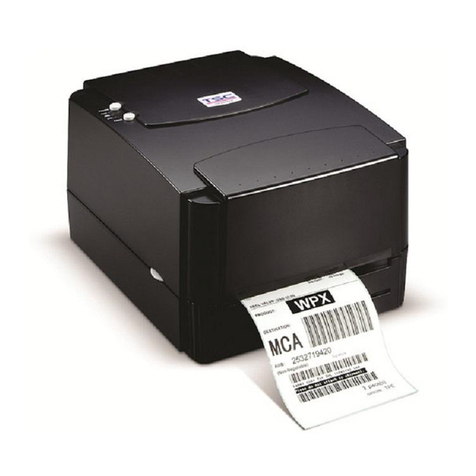
TTP-243 Bar Code Printer
Service Manual
Table Of Contents
1. FUNDAMENTALS ABOUT THE SYSTEM ........................................................................ 1
1.1 Features of the TTP/TDP-243 Series........................................................................... 1
1.2 Model Naming Syntax.................................................................................................. 1
1.3 Overview ...................................................................................................................... 2
1.3.1 Front View............................................................................................................. 2
1.3.2 Rear View............................................................................................................. 3
1.4 Basic Specifications ..................................................................................................... 4
1.5 Effective Print Area....................................................................................................... 6
1.6 Available Bar Codes..................................................................................................... 6
1.7 Various Sensors........................................................................................................... 7
2. SUPPLY SPECIFICATIONS............................................................................................... 9
2.1 Types of Paper............................................................................................................. 9
2.2 Specifications............................................................................................................... 9
2.3 Ribbon Sizes and Shapes.......................................................................................... 11
3. ELECTRONICS ................................................................................................................ 12
3.1 Circuit Description...................................................................................................... 12
3.2 MCU Pin Description.................................................................................................. 15
3.3 Reset Circuit............................................................................................................... 17
3.4 Memory System ......................................................................................................... 17
3.5 Connector Circuit Diagram......................................................................................... 18
3.6 Real-Time Clock Circuit.............................................................................................. 20
3.7 Decode Circuit............................................................................................................ 21
3.8 Thermal Head Drive/ Protection and History Control Circuit...................................... 23
3.9 24V/5V Converter Circuit............................................................................................ 24
3.10 Stepping Motor And DC Motor Driver/ Protection Circuit......................................... 25
3.11 Communication (Serial & Parallel Port) Circuit......................................................... 27
3.12 Cutter Drive Circuit................................................................................................... 28
3.13 Mainboard Replacement.......................................................................................... 29
