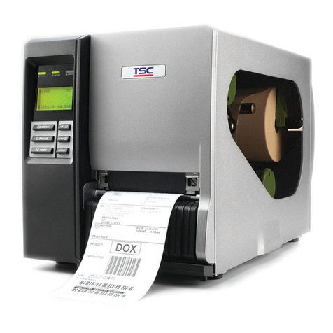
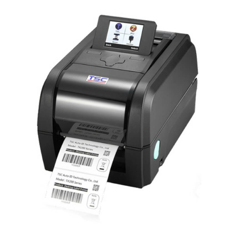
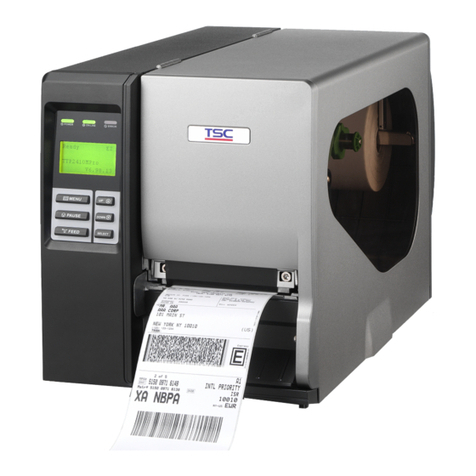
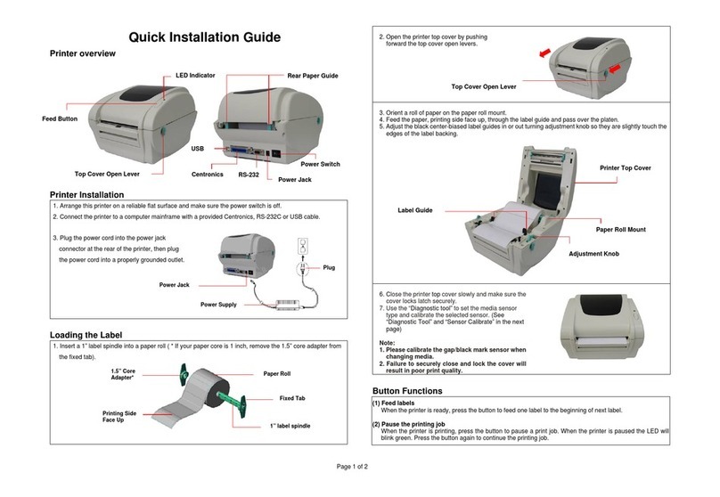
TSC PEX-1120 Series User manual

SERVICE
MANUAL
THERMAL TRANSFER / DIRECT THERMAL
PRINT ENGINE
PEX-1120/ PEX-1130/ PEX-1160 Series
PEX-1220/ PEX-1230/ PEX-1260 Series

i
PEX-1000 Series
Print
Engine Service Manual
TABLE OF CONTENT
1. FUNDAMENTAL OF THE SYSTEM .......................................................................... 1
1.1. Print Engine Orientation........................................................................................1
1.2. Overview.................................................................................................................2
2. ELECTRONICS.......................................................................................................... 5
2.1 Summary of Board Connectors.............................................................................5
2.2 Interface Pin Configuration....................................................................................7
3. MECHANISM ............................................................................................................. 9
3.1 Replacing the Platen Roller Assembly..................................................................9
3.2 Replacing the Print head Assembly ....................................................................10
3.3 Remove the Electronics Cover ............................................................................13
3.4 Replacing the Power Supply Unit........................................................................14
3.5 Replacing Multi-interface (GPIO & parallel) Board ............................................16
3.6 Replacing the Main Board....................................................................................19
3.7 Replacing the Gap/Black Mark Sensor Module..................................................20
3.8 Replacing the Panel Control Board & LCD Panel ..............................................22
3.9 Replacing the Bluetooth Module & Wi-Fi Module ..............................................24
3.10 Replacing the Stepping Motor Assembly .........................................................25
3.11 Replacing the Peel-off Roller Module................................................................26
4. TROUBLESHOOTING............................................................................................. 31
4.1 Common Problems...............................................................................................31
4.2 Mechanism Fine Adjustment to Avoid Ribbon Wrinkles ...................................35
4.3 Adjusting Heater Line...........................................................................................37
5. MAINTENANCE....................................................................................................... 42
UPDATE HISTORY ...................................................................................................... 44

1
PEX-1000 Series
Print
Engine Service Manual
1. FUNDAMENTAL OF THE SYSTEM
1.1. Print Engine Orientation
The PEX-1000 series are available in a left-hand configuration and a right-hand
configuration.
PEX-1120/ PEX-1130/ PEX-1160
series
PEX-1220/ PEX-1230/ PEX-1260
series
Left-hand model
Right -hand model
Note:
This document is going to show the components inside the media compartment of
a left-hand print engine. A right-hand unit contains a mirror image of those
components. Familiarize yourself with those components before continuing with
the print engine setup procedure.

2
PEX-1000 Series
Print
Engine Service Manual
1.2. Overview
Front View
1.
Soft keys
2.
Power switch
3.
LCD display
4.
Wi-Fi antenna (option)
5.
LED indicator
6.
Navigational keys
7.
Media view window
8.
Print engine cover
9.
USB host
2
1
3
4
6
7
5
8
9

3
PEX-1000 Series
Print
Engine Service Manual
Interior View
1. Ribbon rewind spindle
2. Ribbon tension adjustment knobs
3. Print head pressure adjustment knobs
4. Print head release lever
5. Print engine cover open sensor
6. Ribbon supply spindle
7. Label guide bar release lever
8. Media sensor position adjustment knob
9. Platen roller
10.Print head
11.Media sensor
12.Label guide
2
1
3
4
6
5
8
9
10
2
11
12
7

4
PEX-1000 Series
Print
Engine Service Manual
Rear View
* Recommended SD card specification
Type SD card spec
SD
card capacity
Approved SD card manufacturer
Micro SD
V2.0 Class 4
4G
Transcend
V2.0 Class 4
8G
Transcend
V3.0 Class 10 UHS-I
16G
Transcend
V3.0 Class 10 UHS-I
32G
Transcend
V3.0 Class 10
16G
Kingston
V2.0 Class 4
16G
Scandisk
V3.0 Class 10 UHS-I
16G
Scandisk
- The DOS FAT file system is supported for the SD card.
-
Folders/files stored in the SD card should be in the 8.3 filename format.
- The miniSD/microSD card to SD card slot adapter is required.
1. GPIO interface (Applicator interface with DB15F connector +5V I/O)
2. RS-232C interface
3. Ethernet interface
4. USB interface
5. Power cord socket
6. Centronics interface
7. * Micro SD card socket
1
3
2
4
7
6
5
Note:
The interface picture here is for
reference only. Please refer to the
product specification for the interfaces
availability.

5
5
PEX-1000 Series
Print
Engine Service Manual
2. ELECTRONICS
2.1 Summary of Board Connectors
1
21
3 5
9
2
16
17
18
19
13
14
0
10
0
7
8 15
11
22
24
23
20
1
6
4
12

6
6
PEX-1000 Series
Print
Engine Service Manual
Main board
Connector Description
1 USB Host connector
2 Power supply output (5V~24V DC) connector
3 Wi-Fi Module connector
4 Parallel Port board connector
5 GPIO interface board connector
6 Head open sensor connector
7 Gap sensor connector
8 Ribbon encoder sensor connector
9 Power supply output (24V DC) connector
10 BM Sensor connector
11 Paper Distance Sensor connector
12 BT module connector
13 Print head connector
14 LCD panel connector
15 Ribbon end sensor connector
16 TPH Power (24V DC) connector
17 Stepping motor connector
18 Cutter/peel-off connector
19 Paper REWIND connector
20 Micro processor
21 RS-232C connector
22 Ethernet interface
23 MICRO SD card socket
24 USB interface

7
7
PEX-1000 Series
Print
Engine Service Manual
2.2 Interface Pin Configuration
RS-232C
PIN
CONFIGURATION
1 +5 V
2
TXD
3 RXD
4 CTS
5 GND
6
RTS
7 N/C
8
RTS
9 N/C
USB
PIN
CONFIGURATION
1
N/C
2 D-
3
D+
4 GND
Ethernet
PIN
CONFIGURATION
1
Tx+
2 Tx-
3
Rx+
4 N/C
5 N/C
6 Rx-
7
N/C
8 N/C

8
8
PEX-1000 Series
Print
Engine Service Manual
GPIO (Applicator interface with DB15F connector +5V I/O)
Pin
CONFIGURATION
1
GND
2 5V(JP2 short)
3
GPI_1
4 GPI_2
5
GPI_3
6 GPI_4
7
24V
8 GND
9
GPO_1
10 GPO_2
11
GPO_3
12 GPO_4
13
GPO_5
14 GPO_6
15
GPO_7

9
9
PEX-1000 Series
Print
Engine Service Manual
3. MECHANISM
3.1 Replacing the Platen Roller Assembly
1. Open print engine cover.
2. Disengage print head release lever.
3. Remove three screws on the platen holder.
Left-hand model Right -hand model
4. Take out the platen holder, tear bar and platen roller assembly and replace a new platen roller
assembly.
5. Reassemble the parts in the reverse procedures.
Platen roller assembly
Platen holder

10
10
PEX-1000 Series
Print
Engine Service Manual
3.2 Replacing the Print head Assembly
1. Loosen the print head secure screw counterclockwise until it can be taken out from the mechanism.
2. Disengage the print head release lever.
Left-handed configuration Right -handed configuration
3. Carefully disconnect connectors from the print head assembly. Please do not pull the cable to right
and left side alternatively in order to disconnect it from the print head connector. Please use the flat
screw driver to push at the key in the middle of the connector. When the connector becomes loose
from the print head connector, you can disconnect it.

11
11
PEX-1000 Series
Print
Engine Service Manual
4. Remove/Replace the print head assembly.
5. Connect the print head cable and carefully slide print head assembly into the print mechanism.
Make sure the two locating protrusion pins on the print mechanism mounting plate snap into the
locating holes on the print head.
Locating
protrusions
Locating
holes
Locating
protrusions
Locating
holes
Locating
holes
Locating
holes

12
12
PEX-1000 Series
Print
Engine Service Manual
6. Check the print head has been totally closed to the print mechanism before secure the print head by
the previously removed thumbscrew.
7. Reassemble the parts in the reverse procedures.
Note:
Please use the come with new print head secure screw to replace the print head assembly. DO
NOT re-use the original screw.

13
13
PEX-1000 Series
Print
Engine Service Manual
3.3 Remove the Electronics Cover
1. Remove four screws on the electronics cover.
2. Draw out the electronics cover to remove it.
3. Reassemble the parts in the reverse procedures.
Electronics cover

14
14
PEX-1000 Series
Print
Engine Service Manual
3.4 Replacing the Power Supply Unit
1. Refer to section 3.3 to remove the electronics cover.
2. Disconnect three connectors as shown.
3. Remove two screws on power supply cover.

15
15
PEX-1000 Series
Print
Engine Service Manual
4. Pull the power supply unit to loosen the cable tie and disconnect one connector as shown.
5. Remove/Replace the power supply unit.
6. Reassemble the parts in the reverse procedures.

16
16
PEX-1000 Series
Print
Engine Service Manual
3.5 Replacing Multi-interface (GPIO & parallel) Board
1. Refer to section 3.3 to remove the electronics cover.
2. Remove two screws on main board cover.
3. Disconnect the connectors as below shown first then disconnect all connectors on the main board to
take out the main board unit.

17
17
PEX-1000 Series
Print
Engine Service Manual
4. Disconnect two connectors and remove two screws on the multi-interface board.
Note:
This GPIO interface (Applicator interface with DB15F connector +5V I/O) supports internal 5V power supply
(default). For external power supply, please remove the jumper on main board JP2.
Internal power supply (5V I/O)
External power supply (5~24V I/O)

18
18
PEX-1000 Series
Print
Engine Service Manual
5. Remove four screws on the cover as shown to loosen the GPIO and parallel ports.
Note:
Remove two screws to replace multi-interface plate if necessary.
6. Remove/Replace the multi-interface board.
7. Reassemble the parts in the reverse procedures.
This manual suits for next models
5
Table of contents
Other TSC Printer manuals

TSC
TSC MX241P Series User manual

TSC
TSC TTP-245 series User manual

TSC
TSC TE200 series User manual

TSC
TSC TTP-247 User manual

TSC
TSC EZS TDM-30 User manual

TSC
TSC TTP-245 series User manual

TSC
TSC Alpha-3R User manual

TSC
TSC Alpha-30R User manual

TSC
TSC TTP-244 Plus User manual

TSC
TSC PRINTRONIX AUTO ID TC200 Series User manual
Popular Printer manuals by other brands

SNBC
SNBC BTP-M300 Programming manual

Panasonic
Panasonic Network Printing DP2000/2500 Setup guide

Epson
Epson C11CA27201 - WorkForce 40 Color Inkjet... Specifications

Fuji Xerox
Fuji Xerox DocuCentre-IV C3373 Quick reference guide

Samsung
Samsung ML-2165W Remanufacturing instructions

Edimax
Edimax PS-1210MFn manual