Tunstall Lifeline Digital User manual

English Doc. 346 80 21-58. Version 1.1. Revision 01.2022
Lifeline Digital
Art: 022-25-9xx
User manual

Table of Contents
1. Introduction ................................................................................................................................................. 6
1.1. Functionality ......................................................................................................................................... 6
1.1.1. Communication paths ..................................................................................................................... 6
1.1.2. Communication paths for DMP ....................................................................................................... 7
1.1.3. Wi-Fi (WLAN) connectivity .............................................................................................................. 7
1.1.4. Peripherals and radio sensors .......................................................................................................... 7
1.2. About this document ............................................................................................................................. 7
1.2.1. Symbols used in this document ....................................................................................................... 8
2. Overview ..................................................................................................................................................... 9
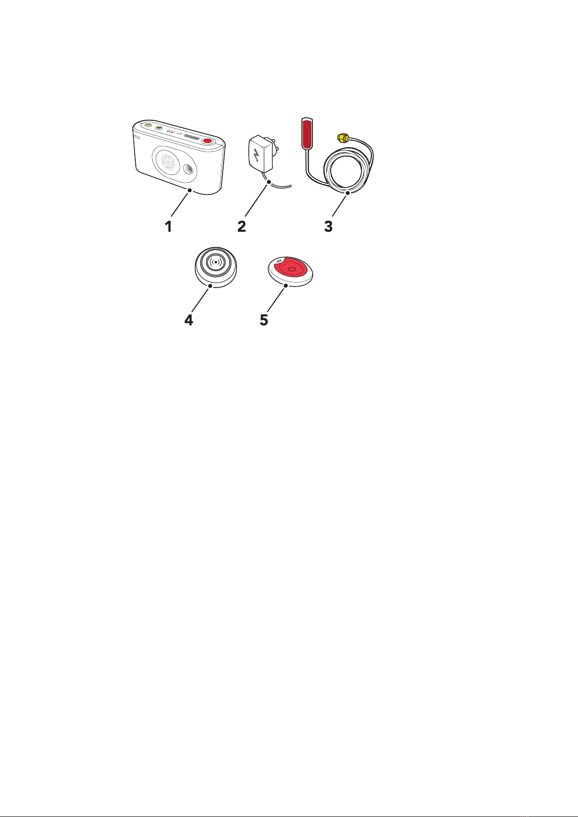
2.1. What's in the box .................................................................................................................................. 9
2.2. Front/top view .................................................................................................................................... 10
2.3. Rear-view ............................................................................................................................................ 10
2.4. Tx4 alarm button/pendant ................................................................................................................... 11
2.5. MyAmie pendant ................................................................................................................................ 11
3. Using Lifeline Digital .................................................................................................................................. 12
3.1. Alarm calls and alarm handling ............................................................................................................ 12
3.1.1. Make an alarm call ....................................................................................................................... 12
3.1.2. Cancel an alarm call ..................................................................................................................... 12
3.2. Home/Away ........................................................................................................................................ 13
3.2.1. Toggle Home/Away mode ............................................................................................................ 13
3.3. Presence/Ready .................................................................................................................................. 13
3.3.1. Activate Presence/Ready mode ..................................................................................................... 13
3.4. Cancel At Source (CAS) ....................................................................................................................... 14
3.4.1. Acknowledge a CAS alarm ............................................................................................................ 14
3.5. Basic Inactivity (BIA) monitoring ........................................................................................................... 15
3.5.1. Manually register activity for BIA monitoring .................................................................................. 15
3.6. Emergency ......................................................................................................................................... 16
3.6.1. Send Emergency alarm ................................................................................................................. 16
3.7. Assistance .......................................................................................................................................... 16
3.7.1. Send Assistance alarm .................................................................................................................. 16
3.8. Manually connect to DMP .................................................................................................................... 16
3.9. System warnings ................................................................................................................................. 17
3.9.1. System warning LED indications .................................................................................................... 17
3.9.2. System warning announcements ................................................................................................... 17
4. Configuration and testing ........................................................................................................................... 18
4.1. Connecting Lifeline Digital .................................................................................................................. 18
4.1.1. Remove and replace the back cover .............................................................................................. 18
4.1.2. Connect the Ethernet cable .......................................................................................................... 18
4.1.3. Connect a USB ............................................................................................................................. 19
4.1.4. Connect to mains power ............................................................................................................... 19
4.1.5. Switch on Lifeline Digital ............................................................................................................... 19
4.1.6. Connect the external cellular antenna (region specific) ................................................................... 19
4.2. Configuring Lifeline Digital in programming mode ................................................................................ 20
4.2.1. Enable programming mode .......................................................................................................... 20
4.2.2. Programming mode and local configuration menu ......................................................................... 20
4.3. Checking cellular signal strength .......................................................................................................... 22
4.3.1. Check cellular signal strength ........................................................................................................ 22
4.4. Checking cellular network status .......................................................................................................... 22
4.4.1. Check cellular network error code ................................................................................................. 22
4.4.2. Check SIM card status .................................................................................................................. 23
4.4.3. Check network status .................................................................................................................... 24
4.4.4. Check cellular radio technology (RAT) ............................................................................................ 25
4.5. Connecting and disconnecting peripherals ........................................................................................... 25
4.5.1. Connect a peripheral in auto pairing mode .................................................................................... 26
4.5.2. Disconnect a peripheral in auto pairing mode ................................................................................ 27
4.5.3. Connect a peripheral in manual pairing mode ................................................................................ 28
4.5.4. Disconnect a peripheral in manual pairing mode ............................................................................ 29

4.6. Testing the radio range of peripherals .................................................................................................. 30
4.6.1. Test the radio range of a peripheral ............................................................................................... 30
4.7. Connecting and disconnecting Nexa smart plugs ................................................................................. 31
4.7.1. Connect a Nexa smart plug in actuator pairing mode ..................................................................... 31
4.7.2. Disconnect a Nexa smart plug in actuator pairing mode ................................................................. 32
4.8. Adjusting speaker volume ................................................................................................................... 33
4.8.1. Adjust speaker volume ................................................................................................................. 33
4.9. Adjusting LED intensity ....................................................................................................................... 34
4.9.1. Adjust LED intensity ..................................................................................................................... 34
5. Maintenance and cleaning .......................................................................................................................... 36
5.1. Replace the backup batteries ............................................................................................................... 36
5.2. Replace battery in the Tx4 alarm button/pendant ................................................................................. 37
5.3. Insert or replace the SIM card .............................................................................................................. 38
5.4. Clean Lifeline Digital ........................................................................................................................... 39
6. Disposal and recycling ............................................................................................................................... 40
6.1. Disposal of batteries ........................................................................................................................... 40
A. Startup mode ............................................................................................................................................ 41
1. Startup mode ........................................................................................................................................ 41
1.1. Connect a peripheral in startup mode .............................................................................................. 41
1.2. Disconnect a peripheral in startup mode .......................................................................................... 42
1.3. Check radio range in startup mode .................................................................................................. 42
1.4. Access local configuration menu in startup mode .............................................................................. 43
1.5. Connect a Nexa Smart plug in startup mode .................................................................................... 44
1.6. Disconnect a Nexa smart plug in startup mode ................................................................................. 45
B. Button functions ........................................................................................................................................ 47
C. Button LEDs .............................................................................................................................................. 48
D. LED indicator status ................................................................................................................................... 49
E. Programming mode diagram ...................................................................................................................... 50
F. Homephone protocol commands ................................................................................................................ 51
7. Technical data ............................................................................................................................................ 52
7.1. Technical details Lifeline Digital ........................................................................................................... 52
7.2. Technical details Tx4 ........................................................................................................................... 53
7.3. Technical details MyAmie .................................................................................................................... 53

5

1. Introduction
Lifeline Digital is an easy-to-use carephone with advanced telecare features that provides 24/7 access to assistance
and remote monitoring. Lifeline Digital is designed to be used primarily by elderly people, people with reduced mobi-
lity or people with long-term health conditions that live independently.
1.1. Functionality
The main functionality of Lifeline Digital is to distribute alarms and events to an alarm receiver or Alarm Receiving
Center (ARC). Alarms and events can be actively triggered by a care recipient or passively by the system. Lifeline Digi-
tal distributes alarms and events according to pre-configured sequences to the receiver or ARC. The type of alarm or
event determines which sequence to use for distribution.
When an alarm call is initiated, the care recipient can use Lifeline Digital as a speakerphone to communicate with the
alarm receiver or ARC operator.
Lifeline Digital primarily communicates using IP protocols via an Ethernet connection or over a 4G network, with fall-
back to 3G and 2G if 4G is unavailable. Lifeline Digital supports VoLTE (Voice over LTE) and VoIP (Voice over Internet
Protocol) voice calls. Analog/GSM communication is also supported.
Lifeline Digital can connect to Tunstall’s Device Management Platform (DMP) which is a cloud-based system that pro-
vides remote management, configuration and monitoring.
Lifeline Digital provides several advanced telecare and time control features that can be customized to fit individual
requirements. In addition, Lifeline Digital has several device monitoring and backup features that continuously ensure
the health of the device.
1.1.1. Communication paths
Lifeline Digital can communicate with receivers and Alarm Receiving Centers (ARCs) across several different communi-
cation paths:
1. Cellular data network using IP protocols, including Voice over LTE (VoLTE)
2. Cellular network for analog/GSM voice calls
3. Ethernet/wired IP network using IP protocols, including Voice over Internet Protocol (VoIP)
4. Wi-Fi (WLAN) for additional connectivity
The cellular communication paths (1 and 2) use the SIM card to connect the device to a network. These communica-
tion paths are used to transmit data such as alarm information and voice calls. Lifeline Digital typically communicates
over the 4G network with fallback to 3G and 2G if 4G is not available. Lifeline Digital supports VoLTE voice calls over
the 4G network.
The device can connect to a wired IP network via a local router or network socket (3). This communication path is used
to transmit data such as alarm information and VoIP voice calls.
The device can connect to a local Wi-Fi network (4) to enable additional connectivity.
6

1.1.2. Communication paths for DMP
Tunstall's Device Management Platform (DMP) is a cloud-based system that provides remote management, configura-
tion and monitoring of connected devices. Lifeline Digital and DMP communicate via:
1. Cellular network data (1)
2. Ethernet/wired IP network (2)
These communications paths are used to transmit heartbeats, configuration and firmware updates between DMP and
connected devices. DMP is not part of the alarm distribution and holds no information of care recipients.
1.1.3. Wi-Fi (WLAN) connectivity
Lifeline Digital has Wi-Fi capability and can either connect to a local Wi-Fi network or be used to create an access
point (AP).
• Connect Lifeline Digital (1) to a local Wi-Fi network (2) to enable additional connectivity
3
2
1
• Configure Lifeline Digital to act as an access point (AP). This configuration can be used to stream video from a sur-
veillance camera (1) via the device (2) to an alarm receiver (3)
3
2
1
1.1.4. Peripherals and radio sensors
Tunstall provides various alarm and telecare peripherals with different types of radio sensors. Available peripherals in-
clude personal alarm buttons/pendants, smoke detectors and door alarms. Tunstall also provides equipment with
third party sensors such as Nexa smart home actuators.
Lifeline Digital supports:
• Tunstall’s bidirectional frequency hopping and can receive radio signals across two separate radio frequencies:
869,2125 MHz and 868,3000 MHz. If the primary frequency is blocked, the device receives the signal across the
secondary frequency (Tunstall Connected radio, two-way protocol).
• European 869 MHz social alarm frequency (Tunstall classic, one-way protocol)
• Bluetooth 5.1 which enables connectivity with, for example, key-less locks
• ZigBee 2.4GHz and Z-wave 868 MHz (EU) connectivity via the USB ports
• Remote operation of Nexa smart home actuators across the 433.92 MHz frequency band
1.2. About this document
This document describes how to use Lifeline Digital and it contains the following sections:
7

1. Introduction, page 6 describes the functionality of Lifeline Digital
2. Overview, page 9 describes the physical appearance of Lifeline Digital
3. Using Lifeline Digital, page 12 describes how to use a device with default configuration
4. Configuration and testing, page 18 describes how to configure and test functionality using the keypad
5. Maintenance and cleaning, page 36 describes how to change batteries and replace SIM card
6. Disposal and recycling, page 40
7. Technical data, page 52 for Lifeline Digital and included pendants
8. Appendices
Some features may be configured differently than described in this document. Contact your supplier or Tunstall if you
have any questions.
1.2.1. Symbols used in this document
WARNING
The warning symbol indicates a serious risk of damage to the equipment or personal injury.
CAUTION
The caution symbol indicates the possibility of damage to the equipment.
NOTE
The note symbol indicates additional information.
8

2. Overview
2.1. What's in the box
2 31 2 3
34 35
1
1. Lifeline Digital
2. Mains power adapter
3. External cellular antenna (region specific)
4. Tx4 alarm button/pendant (region specific)
5. MyAmie pendant (region specific)
Also included in the box:
• Wrist strap and holder for Tx4 alarm button/pendant
(region specific)
• Neck cord and holder for Tx4 alarm button/pendant
(region specific)
• MyAmie neck cord (region specific)
• MyAmie wrist strap (region specific)
9

2.2. Front/top view
11
10
97
21
564
8
3
1. Yellow Extra button
2. Green Cancel button
3. Red Alarm button
4. Green LED indicator
5. Yellow LED indicator
6. Red LED indicator
7. NFC
8. Back cover
9. Microphone
10. IR receiver
11. Speaker
2.3. Rear-view
2
3
1
4
5 6 7 8
9
1. On/Off (I/0) switch
2. Antenna connector
3. Ethernet/network connector
(RJ45 port)
4. Power connector 12V (RJ11 port)
5. Cable slot
6. Security screw (T10) for battery
slot
7. Battery slot
8. SIM card holder inside battery
slot
9. 2x USB 2.0 ports
10

2.4. Tx4 alarm button/pendant
2 31
1. Push-button
2. Red LED indicator, indicates that the Tx4 sensor is transmitting
3. Green LED indicator, indicates that transmission has been received
2.5. MyAmie pendant
11
2
1. Push-button
2. Red LED indicator, indicates that the pendant is transmitting
11

3. Using Lifeline Digital
Some features may be configured differently than described in this document. Contact your supplier or Tunstall if you
have any questions.
3.1. Alarm calls and alarm handling
The main functionality of Lifeline Digital is to distribute alarms and events to an alarm receiver or Alarm Receiving
Center (ARC). Alarms and events can be actively triggered by a care recipient or passively by the system. Lifeline Digi-
tal distributes alarms and events according to pre-configured sequences to the receiver or ARC. The type of alarm or
event determines which sequence to use for distribution.
When an alarm call is initiated, the care recipient can use Lifeline Digital as a speakerphone to communicate with the
alarm receiver or ARC operator.
3.1.1. Make an alarm call
To make an alarm call:
• Press the red Alarm button (1) on the keypad.
Lifeline Digital announces "Do not worry, contacting as-
sistance". The red Alarm button and the green LED indi-
cator flash in unison when the device is calling the alarm
receiver.
1
To make an alarm call using the Tx4 button/pendant:
• Press the push-button (2).
The red LED flashes (3) to indicate that the alarm is
transmitted to Lifeline Digital. The green LED flashes (4)
when the alarm is acknowledged by Lifeline Digital. Life-
line Digital announces "Do not worry, contacting assis-
tance".
4
3
2
To make an alarm call using the MyAmie pendant:
•Press the push-button (5).
The red LED flashes (6) to indicate that the alarm is
transmitted to Lifeline Digital. Lifeline Digital announces
"Do not worry, contacting assistance".
5
6
3.1.2. Cancel an alarm call
To prevent false alarms it is possible to cancel an alarm call before it is connected to the receiver or Alarm Receiving
Center (ARC).
To cancel an alarm call:
12

• When Lifeline Digital announces "Press the Cancel but-
ton to cancel the alarm", press the green Cancel button
(1).
The device announces "The alarm has been cancelled".
1
3.2. Home/Away
The Home/Away feature is used to notify the system and the Alarm Receiving Center (ARC) when the care recipient is
away (or home). In the Away mode some functions and alarms are modified or suspended to avoid false alarms.
3.2.1. Toggle Home/Away mode
NOTE
This feature must be enabled.
To toggle Away mode:
•Press and hold the green Cancel button (1) until you
hear a rising sound signal and the green Cancel button
starts to flash, then release the button.
The device announces "Away" and the green Cancel
button LED switches on to indicate that Away mode is
active.
1
To toggle Home mode:
• Press and hold the green Cancel button (1) until you
hear a rising sound signal, then release the button.
The device announces "Home".
3.3. Presence/Ready
The Presence/Ready feature is used to notify the system and the Alarm Receiving Center (ARC) when a caregiver is
present and when the caregiver is ready to depart. Optionally, a deactivation timer can be configured to automatically
deactivate Presence mode in case a caregiver forgets to register Ready before departing. In Presence mode some
alarm functionality is modified and the Assistance feature can be enabled.
3.3.1. Activate Presence/Ready mode
NOTE
This feature must be enabled.
13

To activate Presence mode:
• Press and hold the green Cancel button (1) then press
the red Alarm button (2) twice and release all buttons.
The yellow LED indicator switches on to indicate that
Presence mode is active.
To activate Ready and deactivate Presence mode:
• Press and hold the green Cancel button (1) then press
the red Alarm button (2) twice and release all buttons.
12
3.4. Cancel At Source (CAS)
The Cancel At Source (CAS) feature repeats an active alarm until a caregiver physically cancels the alarm by pressing
the green Cancel button on the device. CAS can be used to ensure that high dependency care recipients are visited
before an alarm is completely cleared/acknowledged.
3.4.1. Acknowledge a CAS alarm
NOTE
This feature must be enabled.
NOTE
This feature may be configured differently.
The yellow LED indicator flashes slowly (2 seconds on/ 2 seconds off) to indicate that an active CAS alarm is present.
To acknowledge a CAS alarm:
• Press the green Cancel button (1).
1
14

3.5. Basic Inactivity (BIA) monitoring
The Basic Inactivity (BIA) monitoring generates an inactivity alarm if no activity is detected within a certain time. Activi-
ty is typically registered by pressing the yellow Extra button or passively triggering a motion sensor. Optionally, BIA
can also be used as input for reporting Activities of Daily Life (ADL) to the Alarm Receiving Center (ARC).
NOTE
When the system is set to Away mode, no alarm is generated.
3.5.1. Manually register activity for BIA monitoring
NOTE
This feature must be enabled.
NOTE
When Lifeline Digital is switched on, you must press the yellow Extra button to activate BIA monitor-
ing.
The yellow button LED slowly flashes (0.5 seconds on/ 9.5 seconds off) when Basic Inactivity (BIA) monitoring is ena-
bled. If the device is set to Away mode, no inactivity alarms will be generated.
To manually register activity for BIA monitoring:
• When the device announces "An inactivity alert is about
to be made, please press cancel", press the yellow Ex-
tra button (1).
1
To temporarily disable BIA monitoring:
a) Press and hold the green Cancel button (2), then press
the yellow Extra button (3) and release all buttons.
The yellow button LED flashes slowly (0.5 seconds on/
14.5 seconds off) to indicate that BIA monitoring is tem-
porally disabled.
3 2
b) Press the yellow Extra button (3) to start or resume BIA
monitoring.
15

3.6. Emergency
The Emergency feature allows a caregiver to send an emergency alarm via Lifeline Digital using a personal alarm trig-
ger.
3.6.1. Send Emergency alarm
NOTE
This feature must be enabled.
To send an emergency alarm:
• Trigger the personal (staff) alarm button/pendant.
3.7. Assistance
The Assistance feature allows a caregiver to send an assistance alarm if additional help is required. This function is
only available in Presence mode.
3.7.1. Send Assistance alarm
NOTE
This feature must be enabled.
To send an assistance alarm when the device is set to Presence mode:
• Press the red Alarm button (1) or trigger the alarm but-
ton or pendant (2).
2
1
3.8. Manually connect to DMP
If the device is registered to Tunstall's Device Management Platform (DMP), you can manually connect to DMP to
download configuration or firmware updates.
To manually connect to DMP:
a) Press and hold the yellow Extra button (1).
16

b) When the device emits a rising sound signal and the yel-
low LED indicator starts to flash, release the button.
The device attempts to connect to DMP and announces
either:
• "Connected to DMP" when a connection is establish-
ed.
• "Connection attempt to DMP failed" if all connection
attempts fail.
1
3.9. System warnings
System warnings are visual (LED) and audio indications that notifies the care recipient or caregiver of power and con-
nectivity errors.
3.9.1. System warning LED indications
1
1. Red LED indicator
System warning indications a/bStatus
Red LED flashing x1 Media processor/Ethernet failure
Red LED flashing x2 Mains power failure
Red LED flashing x3 Backup battery low
Red LED flashing x4 Cellular modem failure
Red LED flashing x5 Radio failure/interference
aFeature must be enabled.
bNote that if several error conditions are present they are presented sequentially with a 2 second pause between indications. For example, two
consecutive flashes followed by a pause and three consecutive flashes indicates that there is a mains failure and that the battery is low
3.9.2. System warning announcements
Announcement Description
"Warning" Warning announcement that is followed by a warning message
"There is no mains power" AC power to the device is lost
"Mains power is restored" AC power to the device is restored
"Battery low" The backup battery is low
"Reduction in radio range detected" Radio interference is detected
"Radio system restored" No radio interference is detected, and the radio system is restored
"Ethernet connection failure" The Ethernet cable is disconnected
"Ethernet connection restored" The Ethernet cable is reconnected
"Cellular data connection failure" The cellular data connection is failing
"Cellular data connection restored" The cellular data connection is restored
17

4. Conguration and testing
This section describes how to configure and test Lifeline Digital using the buttons on the keypad.
4.1. Connecting Lifeline Digital
4.1.1. Remove and replace the back cover
NOTE
Only remove the back cover for installation, configuration, or maintenance. The back cover protects
the device from tampering.
To remove and replace the back cover:
a) Push and slide out the back cover to remove it (1).
b) Run all cables through the cable slot (2).
c) Replace the back cover when installation, configuration
or testing is completed (3).
2
1
3
4.1.2. Connect the Ethernet cable
An Ethernet connection is required for wired IP communication.
NOTE
The Ethernet cable is not supplied by Tunstall.
To connect an Ethernet cable:
a) Insert the Ethernet cable into the Ethernet port on the
device (1).
1
b) Connect the other end of the Ethernet cable into the lo-
cal internet router or network socket.
18

4.1.3. Connect a USB
The USB ports provide additional connectivity for ZigBee and Z-Wave dongles.
To connect a USB:
• Insert the USB plug into an available USB port (1).
1
4.1.4. Connect to mains power
CAUTION
Only use power adapters supplied by Tunstall.
To connect to mains power and power up:
a) Insert the power adaptor cable into the 12V connector
on the device (1).
b) Connect the mains power adaptor into a wall socket (2).
2
1
4.1.5. Switch on Lifeline Digital
To switch on Lifeline Digital:
• Set the On/OFF switch to 1 (ON) to power up the device
(1).
The green and yellow LED indicators starts to flash rap-
idly to indicate startup progress.
The device is ready when the LED indicators stop flash-
ing.
1
4.1.6. Connect the external cellular antenna (region specic)
If required, connect the external antenna:
a) Screw the antenna cable onto the antenna connector (1).
19

b) Determine a suitable location with strong cellular signal
for the antenna using the cellular strength test, see
Check cellular signal strength , page 22.
1
c) When installation, configuration and testing is comple-
ted, remove the adhesive cover from the back of the an-
tenna (2) and fix the antenna in the selected location (3).
The location must be:
• A non-metallic surface
• Indoors, the antenna is not water-resistant
23
4.2. Conguring Lifeline Digital in programming mode
4.2.1. Enable programming mode
To enable programming mode:
a) Press and hold the green Cancel button (1), then press
and hold the red Alarm button (2) and the yellow Extra
button (3).
2
31
b) Release all buttons when the device emits a rising sound
signal and announces "Programming mode”.
The LED indicators start chaser sequence and the button
LEDs flash in unison to indicate that the programming
mode is enabled.
c) Press the green Cancel button (1) to exit programming
mode. The device automatically exits Programming
mode if no button is pressed for 20 seconds.
4.2.2. Programming mode and local conguration menu
a) Enable programming mode, see Enable programming
mode, page 20.
20

b) Select a function in Programming mode:
• Press and hold the yellow Extra button until the de-
vice announces the number of the menu position you
want to select according to the Local configuration
menu.
For example, the device announces “One” for speak-
er volume, “Two” for LED intensity and “Three” for
Radio test mode.
• Optionally, press the yellow Extra button the number
of times that corresponds to the menu position you
want to select according to the Local configuration
menu.
For example, press once to select speaker volume,
press twice to select LED intensity or press three times
to select Radio test mode.
c) Select a radio sensor position in Programming mode:
• Press and hold the red Alarm button until the device
announces “Auto pairing mode” or the number of the
radio position you want to select according to the Lo-
cal configuration menu.
• Optionally, press the red Alarm button the number of
times that corresponds to the radio position you want
to select according to the Local configuration menu.
d) Press the green Cancel button to exit programming
mode.
Menu position AnnouncementaDescription
Yellow Extra button
1 "One" Adjust speaker volume
2 "Two" Adjust LED intensity
3 "Three" Radio test mode
4 "Four" Test cellular signal
strength
5 "Five" Cellular status
1 "One" Error code (default)
2 "Two" Check SIM card status
3 "Three" Check cellular network
status
4 "Four" Check cellular radio tech-
nology
8 "Eight" Nexa/actuator pairing
mode
Red Alarm button
1 "One" Radio sensor position 1
2 "Two" Radio sensor position 2
3 "Three" Radio sensor position 3
4-64 "Four" - " Sixty-
four"
Radio sensor position
4-64
Green Cancel button
Go back / Exit
aIf speech messages are disabled, beeps replace the announcements. For example, the device emits one beep for speaker volume, two beeps for
LED intensity and three beeps for radio test mode.
21
Other manuals for Lifeline Digital
4
This manual suits for next models
1
Table of contents
Other Tunstall Personal Care Product manuals

Tunstall
Tunstall Care@Home C7000 Troubleshooting guide

Tunstall
Tunstall SmartLink Medi Guardian MKII 4G Troubleshooting guide

Tunstall
Tunstall iVi User manual

Tunstall
Tunstall Liberty 300 User manual

Tunstall
Tunstall GO User manual

Tunstall
Tunstall liberty300 Troubleshooting guide

Tunstall
Tunstall Lifeline Vi Installation guide

Tunstall
Tunstall Home box User manual

Tunstall
Tunstall Lifeline Digital User manual

Tunstall
Tunstall VitalBase VBC3 User manual