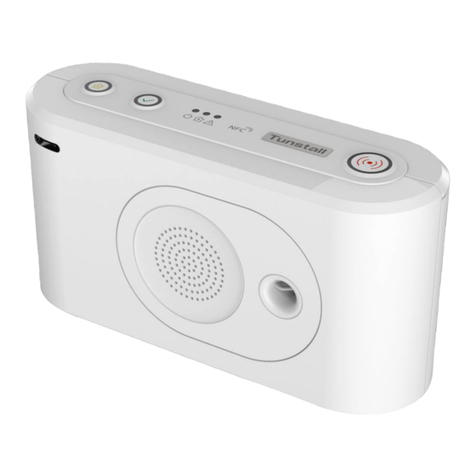
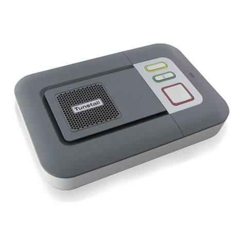
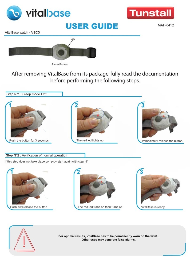
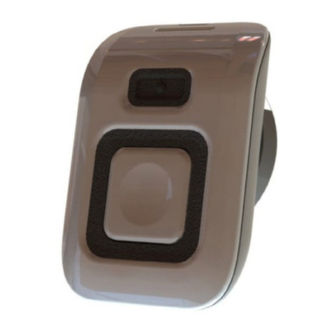
Tunstall Lifeline Digital 022-25-9 Series User manual

English Doc 346 80 21-59 Version 1. Revision 09.2021
Lifeline Digital
Art. 022-25-9xx
Quickstart guide

Table of Contents
1. Lifeline Digital Quickstart guide .................................................................................................................... 4
1.1. Overview .............................................................................................................................................. 4
2. Install Lifeline Digital .................................................................................................................................... 5
3. Connect a peripheral ................................................................................................................................... 7
4. Lifeline Edith ............................................................................................................................................... 8
4.1. Connect Lifeline Digital to Lifeline Edith ................................................................................................. 8
4.2. Configure common settings ................................................................................................................... 9
4.3. Disconnect Lifeline Digital from Lifeline Edith ....................................................................................... 10
A. Programming mode diagram ..................................................................................................................... 11

1. Lifeline Digital Quickstart guide
This quickstart guide describes how to install Lifeline Digital and configure common settings using either Lifeline Edith
or Tunstall's Device Management Platform (DMP).
For more information, refer to Lifeline Digital installation guide.
1.1. Overview
1
11
7
6
54
2
3
8
9
10
12 13 14
15 16 17 19 2018
1. Red Alarm button
2. Green Cancel button
3. Yellow Extra button
4. Green LED indicator
5. Yellow LED indicator
6. Red LED indicator
7. NFC
8. Microphone
9. IR receiver
10. Speaker
11. Back cover
12. On/Off (I/0) switch
13. Antenna connector
14. 2x USB 2.0 ports
15. Ethernet/network con-
nector (RJ45 port)
16. 4. Power connector 12V
(RJ11 port)
17. Cable slot
18. Security screw (T10) for
battery slot
19. Battery slot
20. SIM card holder inside
battery slot
4

2. Install Lifeline Digital
a) Remove the back cover (1).
1
b) For Ethernet/wired IP connectivity, connect Lifeline
Digital to a local router or Ethernet socket:
i. Insert an Ethernet cable into the Ethernet/
Network (RJ45) connector on the device (2).
ii. Connect the other end of the Ethernet cable to a
local router or Ethernet socket.
2
c) For cellular connectivity, insert the SIM card provided
by your supplier or Tunstall.
If the device is delivered with a pre-installed SIM
card, skip this step.
i. Unscrew the security screw using a T10 torx
screwdriver (3).
ii. Pull out the battery holder from the battery slot
(4).
3
4
iii. Insert the SIM card (standard/mini-SIM size) in
the SIM card slot (5). Make sure that the metallic
chip is facing down and that the SIM card notch
is aligned as shown in the illustration.
iv. Insert the battery holder into the battery slot (6).
If it is a tight fit, carefully press down on the SIM
card with your finger.
5
6
v. Screw the security screw back in place using the
T10 torx screwdriver.
d) Connect Lifeline Digital to mains power:
i. Insert the mains power adapter cable into the
12V socket (7).
ii. Connect the mains power adaptor to a wall sock-
et (8).
7
8
e) Set the ON/OFF switch to 1 (ON) to power up the
device (9).
The green and yellow LED indicators starts to flash
rapidly to indicate start-up progress.
The device is ready when the LED indicators stop
flashing.
9
f) For devices with cellular connectivity, check to ensure
that cellular signal strength is sufficient:
i. Press and hold the green Cancel button (10),
then press and hold the red Alarm button (11)
and the yellow Extra button (12).
5

1012 11
ii. Release all buttons when the device emits a ris-
ing sound signal and announces "Programming
mode".
The LED indicators start chaser sequence and
the button LEDs flash in unison to indicate that
the programming mode is enabled.
iii. Press and hold the yellow Extra button (13).
13
iv. When the device announces "Four", release the
button.
The device announces the current signal
strength:
• “Cellular signal strength is One" for poor cel-
lular signal strength.
• "Cellular signal strength is Two"
• "Cellular signal strength is Three"
• "Cellular signal strength is Four"
• “Cellular signal strength is Five” for excellent
cellular signal strength.
v. If necessary, adjust position of the device to im-
prove cellular signal strength.
vi. Press the green Cancel button (14) to exit cellu-
lar signal test.
vii. Press the green Cancel button (14) again to exit
programming mode.
14
g) If the device is registered to Tunstall's Device Man-
agement Platform (DMP), you can manually connect
to DMP to download configuration and firmware up-
dates:
i. Press and hold the yellow Extra button (15) for
10 seconds.
15
ii. When the device emits a rising sound signal and
the yellow LED indicator starts to flash, release
the button.
The device attempts to connect to DMP and an-
nounces either:
• "Connected to DMP" when a connection is
established.
• "Connection attempt to DMP failed" if all con-
nection attempts fail.
h) Replace the back cover.
6

3. Connect a peripheral
a) Press and hold the green Cancel button (1) then
press and hold the red Alarm button (2) and the yel-
low Extra button (3).
13 2
b) When the device emits a rising sound signal and an-
nounces "Programming mode", release all buttons.
The LED indicators start chaser sequence and the
button LEDs flash in unison.
c) Press and hold the red Alarm button (4).
4
d) When the device announces “Auto pairing mode”,
you can either:
• Release the button to enable auto paring mode.
In auto paring mode the peripheral is stored in the
first available radio sensor position.
• Continue to hold the button until the device an-
nounces the number of the radio sensor position
you want to select, then release the button.
In manual pairing mode the peripheral is stored at
the selected radio sensor position.
e) When the device announces "Activate transmitter
now, activate/trigger the peripheral (5).
The device announces:
• “Operation succeeded” if the peripheral was suc-
cessfully connected.
• “Battery low” if the battery of the peripheral is low.
• “Operation failed” followed by an error code if the
connection failed.
• “Error code One” if the device memory is full.
• “Error code Two” if the peripheral is already con-
nected to the device.
5
f) Press the green Cancel button (6) to save current set-
tings and exit.
6
7

4. Lifeline Edith
Lifeline Edith is a configuration software for PC that can be used to configure any parameter setting or to apply a pre-
pared configuration file to the device. It is also possible to create backup files and new configuration files that can be
applied to other devices.
To configure Lifeline Digital using Lifeline Edith you require:
• A PC computer with Lifeline Edith software
• An Opto Iso cable
• A list of all values and parameter settings to be configured. Do not change any settings or values unless advised by
your supplier or Tunstall
• Optionally, a configuration file (.cfw file) with pre-configured settings
4.1. Connect Lifeline Digital to Lifeline Edith
a) Connect the modular cable marked
"Carephone /HT" to the 12V connector (RJ11) on the
device (1).
b) Connect the USB cable to a PC with Lifeline Digital
(2).
c) Connect the mains adapter to a wall socket (3).
1
2
3
d) Launch Lifeline Edith.
e) Click Local connection in the sidebar menu.
f) When the Identify carephone window opens, switch
on the device. If it is already switched on, switch it off
and on again
The connection is ready when the device information
is displayed in the sidebar menu under Connection.
g) If a configuration file has been provided by your sup-
plier or Tunstall:
i. Click Read from le in the sidebar menu and se-
lect the configuration file (.cfw).
ii. If required, configure common settings, see
Configure common settings, page 9.
iii. Click Save all to carephone to save the settings
to the connected device.
h) If required, load and configure settings directly from
the connected device:
i. Click Read from carephone in the sidebar menu
to load the current settings from a device.
ii. Configure common settings, see Configure com-
mon settings, page 9.
iii. Click Save all to carephone to save the settings
to the connected device.
8

Optionally, click Save changes to carephone to
save only the affected settings to the connected
device.
4.2. Congure common settings
a) Go to Common settings.
b) Set the speaker volume in the Volume field or click
and drag the Volume slider.
c) If required, enter the APN of the cellular operator in
the APN field.
d) If required, enter the telephone number for cellular
callback in the Callback phone number field.
NOTE
Use international telephone number
format, for example: "+46[...]" or
"0046[...]".
e) Select language for announcements in the Speech
messages language drop-down list.
f) Select the appropriate time zone in the Time zone
drop-down list.
g) If required, configure the main alarm code/ID:
i. Enter the main alarm code/ID in the Main alarm
code/ID field.
ii. Click Set.
The main alarm code/id appears in all Alarm code/ID
fields.
h) Configure GPRS/IP connection details for the primary
receiver on the Address a row:
i. Enter the IP address or FQDN in the Address
field.
ii. Select a communication protocol in the Protocol
drop-down list:
•Tunstall IPACS
•SCAIP
•Homephone-SIP
•EN50134-9
iii. Enter alarm code/ID in the Alarm code/ID field.
This is not required if the main alarm code/ID is
already set.
iv. If required, select a SIP account in the SIP ac-
count drop-down list. The SIP account must be
configured separately, see Step j) .
v. Select a connection option in the Connection
type drop-down list:
•Wired for Ethernet/wired IP connection
•Cellular for cellular connection
•WLAN for Wi-Fi connection. Additional con-
figuration is required, go to GPRS/IP > IP/
WLAN)
•Auto. The system automatically determines
connection type based on the selected con-
nectivity methods
vi. Select an option for voice communication in the
Speech method drop-down list:
•VoIP
•Callback
•Dial out
•Auto. The Alarm Receiving Center (ARC) de-
termines speech method.
i) If required, configure connection details for secon-
dary receiver on the Address b row, see the previous
step.
j) If required, configure SIP account 1:
i. Enter SIP account username in the User name
field.
ii. Enter SIP password in the Password field.
iii. Enter the telephone number for dial out in the
Dialout phone number field.
NOTE
Use international telephone
number format, for example:
"+46[...]" or "0046[...]".
iv. Enter the number of redial attempts to made in
the Retries field.
k) Select connectivity methods for the device:
CAUTION
Only select connectivity methods
that are to be used by the system.
Incorrect configuration may cause
device monitoring disruption and
connection failure.
•Ethernet for Ethernet/wired IP connectivity
•Cellular for cellular connectivity
•Wi for WLAN connectivity
l) Click Save all to carephone to save all settings to
the connected device.
9
4.3. Disconnect Lifeline Digital from Lifeline Edith
a) Click Disconnect in the sidebar menu,
b) Disconnect the Opto Iso cable from the device.
c) Switch off the device.
d) Connect the device to mains power.
e) Switch on the device.
10

Appendix A. Programming mode diagram
Adjust speaker volume
Adjust LED intensity
Test cellular signal strength
Cellular status
Radio test mode
Cellular error code
Check SIM status
Check cellular network
status
Check cellular radio
technology (RAT)
Actuator pairing
On code
OFF code
Auto pairing mode
Programming mode - Local configuration menu
Standby mode
Manual pairing mode
Radio sensor
Radio sensor
Radio sensor
Radio sensor
Radio sensor
1
1
1
2
2
2
3
3
3
4
4
5
8
11

www.tunstall.com
Our policy of continual development means that product specification and appearance may change without notice.
Tunstall does not accept responsibility for any errors and omissions within this document.
© 2021 Tunstall Group Ltd. ® Tunstall is a registered trademark.
Tunstall declare that this radio equipment is in compliance with Directive 2014/53/EU. The full text of the EU declara-
tion of conformity is available at the following address: https://www.tunstall.com/lifeline-digital-documentation
Radio power: The transmitted power in the actual frequency band is less than 1mW e.r.p
Tunstall AB
Box 31044
200 49 Malmö
Sweden
Visiting address:
Hyllie Boulevard 10B, Malmö
Tel: +46 20-66 11 11
E-mail: [email protected]
Table of contents
Other Tunstall Personal Care Product manuals

Tunstall
Tunstall VitalBase VBC3 User manual

Tunstall
Tunstall SmartLink Medi Guardian MKII 4G Troubleshooting guide

Tunstall
Tunstall Liberty 300 User manual

Tunstall
Tunstall iVi User manual

Tunstall
Tunstall Vi User manual

Tunstall
Tunstall Lifeline Digital User manual

Tunstall
Tunstall GO User manual

Tunstall
Tunstall Lifeline Vi Installation guide

Tunstall
Tunstall liberty300 Troubleshooting guide

Tunstall
Tunstall Lifeline Digital User manual