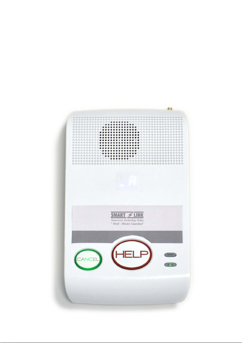
Tunstall SmartLink Medi Guardian MKII 4G Troubleshooting guide

SmartLink Medi Guardian MKII 4G
User & Installation Guide

page 2 of 16TS-UG-AP-017-010
Your SmartLink Medi Guardian MKII 4G medical alarm
unit
The SmartLink Medi Guardian MKII 4G home unit offers connection via
the mobile 4G GSM network. It enables you to generate a call for help by
immediately contacting the Customer Care Centre, where the Care Consultant
will be able to provide you with the assistance you require.
Front view

page 3 of 16TS-UG-AP-017-010
Back view (Diagram 2)

page 4 of 16TS-UG-AP-017-010
Getting started
Before you start using your SmartLink Medi Guardian MKII 4G alarm, please
complete the following instructions.
Please note: This alarm has been pre-programmed to automatically connect to
the Tunstall Customer Care Centre.
DO NOT REPROGRAM THIS ALARM.
Step 1 - Unpack the box
Please ensure the following accessory items are enclosed:
Pendant, Neck chain, Wrist
Strap with connectors
Short stub
antenna
Optional External
antenna (if requested)

page 5 of 16TS-UG-AP-017-010
Step 2 - GSM connection: (SIM card required)
If your alarm has been provided with a SIM already installed, please skip to
Step 3.
SIM card selection
If your alarm has not been provided with a SIM card please arrange and insert a
SIM card.
In order to use the GSM mobile network a full sized SIM card must be fitted
into the SmartLink Medi Guardian MKII 4G alarm.
• The SIM fits into the slot, as labelled ‘SIM’. Insert the SIM card with the gold
contact side of the SIM facing down by pushing it into the base alarm unit
until it clicks, then release.
• To remove the SIM card, push the SIM card gently into the unit until it clicks
and then release. The SIM card will eject and can then be taken out of the
base alarm unit.
Note: When operating over a GSM network, the base alarm unit will not work
unless there is satisfactory GSM coverage by the SIM service provider, and the
SIM is active. See page 7 for further information on status LED signal strength
and attaching an external antenna if required.
Step 3 - Situate your alarm
Decide where you wish to situate your new alarm unit in your home. Remember
it should be within two metres of a mains power wall socket.

page 6 of 16TS-UG-AP-017-010
Step 4 - Connect the mains power adaptor
Plug the black mains adaptor into the base alarm unit socket labelled ‘POWER’
and plug into a power point in your home (mains power).
Turn on both the mains power and the battery switch located underneath the
alarm. Wait one minute for the alarm display to go blank.
Step 5- Checking the cellular signal strength
Important: When operating over the GSM mobile network, the base alarm
unit requires an average GSM signal in order to operate efficiently. To obtain
this, attach the short stub antenna to the gold GSM antenna port at rear of the
alarm.
POWER
Battery
switch

page 7 of 16TS-UG-AP-017-010
When the SmartLink Medi Guardian MKII 4G unit is in normal/operation mode,
press the green cancel button on the base alarm unit and the signal strength
will be displayed for two seconds.
Note: An external antenna is available to purchase for clients in poor
GSM coverage areas. Please contact Tunstall Customer Service Centre on
1800 603 377 for more information.
If required installation instructions are outlined on Page 8.
Step 6 - Place a test call
Press the blue button (diagram below) on your SmartLink Medi Guardian MKII
4G pendant to place a test call to the Tunstall Customer Care Centre. Advise
the Care Consultant that you are installing your new SmartLink Medi Guardian
MKII 4G alarm.
The customer care consultant will confirm your details and complete the
installation process with you.
to
The base alarm unit will display the signal strength from 0
to 9.
0-1 = Weak signal
2-5 = Average signal
6-9 = Strong signal
The base alarm unit updates the signal strength every
minute.

page 8 of 16TS-UG-AP-017-010
Connecting the external GSM antenna (if applicable)
Attaching an external antenna
1. Attach the external GSM antenna (as displayed in Image 1) to the gold GSM
antenna port at the rear of the alarm.
2. Place the antenna in the area it will eventually be fixed. The correct
positioning of the antenna is very important in low signal areas. To maximise
the signal, it is best to position both the alarm and antenna in an open area
with clear line of sight outside e.g. near a window (as displayed in Image 2).
Make sure the antenna cable is unraveled fully and do not remove the sticky
backing until enhanced signal strength has been confirmed from the desired
location with a successful test call to the Customer Care Centre.
3. Place a test call by pressing the red Help button on your alarm and advise
the operator that you have fitted an external antenna to your alarm.
4. Once a successful test has been made, mount the antenna by removing the
plastic backing and stick it firmly in place.
Note: If you find, after following the above instructions, that the alarm signal
strength is still below recommended levels, you may require a High Gain
external antenna, and should contact Tunstall’s Customer Service Centre on
1800 603 377 for further information.
Image 1 Image 2

page 9 of 16TS-UG-AP-017-010
Using your medical alarm unit
False alarms
If you accidentally raise a false alarm, please do not worry, Tunstall’s Customer
Care Centre is always happy to hear from you and the raising of the alarm call
acts as a useful test of your alarm unit.
Making an alarm call
Press the blue help button on the pendant or the red help
button on the base alarm unit. The base alarm unit will
beep when a call is activated. When the call is answered in
the Customer Care Centre, the base alarm unit will beep
several times. Tell the consultant why you have activated
the alarm call and they will arrange for assistance.
Cancelling an alarm call
To cancel an alarm call, press the green cancel button on
the base alarm unit within 10 seconds of activation. The
alarm call will be cancelled.

page 10 of 16TS-UG-AP-017-010
Status warnings
Warnings/status lights on the base alarm unit
The base alarm unit has warning and status lights to clearly indicate the unit’s
current status. When functioning correctly your SmartLink Medi Guardian MKII
4G base alarm unit will normally look like this:
How to respond to warnings
Display Warning What to do
AC power failure Check the home unit is plugged
into a working electrical socket
The alarm unit has a low
battery
Check the home unit is plugged
into a working electrical socket
and the battery switch is turned
ON.
The alarm unit failed to send
a message.
Check the antenna/SIM card is
plugged in to the alarm unit.
or The cellular connection has
failed or SIM card is missing.
Check the Antenna/SIM card is
plugged in to the alarm unit.
or
Is on the Display and the red
Help button is flashing- The
red button on the alarm unit
has been pressed.
Nothing, an alarm call has been
raised to the Customer Care
Centre.
to Pendants No. 1 to 8 has been
Pressed.
Nothing, an alarm call has been
raised to the Customer Care
Centre.
The ‘MAINS ON’ light
and the ‘CANCEL’
(green) button should
be on

page 11 of 16TS-UG-AP-017-010
Pendants No. 1 to 8 has been
Pressed.
Nothing, an alarm call has been
raised to the Customer Care
Centre.
Pendants No. 1 to 8 has been
Pressed.
Nothing, an alarm call has been
raised to the Customer Care
Centre.
Pendants No. 1 to 8 has been
Pressed.
Nothing, an alarm call has been
raised to the Customer Care
Centre.
Detectors No. 1 to 8
Programmed as Fire “Fi”
Option has been Activated.
Nothing, an alarm call has been
raised to the Customer Care
Centre.
to Pendant has detected a low
battery.
Contact your installer or Customer
Care Centre.
Detectors No. 1 to 8 has
detected a Low Battery.
Contact your installer or Customer
Care Centre.
If the warnings persist please contact Tunstall Customer Service on 1800 603 377.

page 12 of 16TS-UG-AP-017-010
Your pendant
Your pendant (personal radio trigger) is wirelessly connected to your SmartLink
Medi Guardian MKII 4G home unit and enables you to generate a call for help
from anywhere in your home or garden. The pendant should be worn at all
times and can be worn around the neck or on the wrist using the attachments
supplied. Your pendant is water resistant (to IP67 standard) up to one metre for
30 minutes. It can be worn in the shower however wearing it in the bath should
be avoided where possible.
The pendant has the below features:
NOTE: ON activation, the pendant will send a notification message via the base alarm unit to the
Customer Care Centre when its battery is low.
LED on the pendant
When pressed, the LED on your pendant will light up red. This is to indicate
that the blue help button has been pressed. If the LED flashes green when
pressed this indicates that the pendant is out of range or not operating
correctly. If the LED flashes red when pressed, this indicates that the battery is
low and should be replaced.
Up to 300m radio
range (typical)
Water resistant Low Battery re-
porting*

page 13 of 16TS-UG-AP-017-010
Help and advice
Do’s
• Do wear your pendant at all times.
• Do test your pendant and base alarm unit on a monthly basis with the
Customer Care Centre.
• Do keep the base alarm unit connected to the mains power at all times.
• Do regularly wipe clean your base alarm unit and pendant with a
soft cloth which can be slightly moistened with a gentle detergent if
required.
Don’ts
• Don’t expose the base alarm unit to water or other liquids.
• Don’t connect cables other than those supplied with the alarm unit.
• Don’t move the base alarm unit from the location where it was originally
installed.
• Don’t move objects close to the base alarm unit that are made of metal
or create excessive noise or heat, such as televisions, radios, washing
machines, microwave ovens, Wi-Fi routers, mobile phones, laptops etc.
Battery information
The SmartLink Medi Guardian MKII 4G alarm contains a Nickel Metal Hydride
back-up battery that recharges itself when plugged into the mains power. It
is recommended that the battery be replaced after five years. The battery
provides up to 40 hours of standby operation.
All batteries should be disposed of in accordance with the latest legislation.

page 14 of 16TS-UG-AP-017-010
Notes

page 15 of 16TS-UG-AP-017-010
Technical Details
Weight: 590g (including battery)
Dimensions: 210 x 130 x 35 mm (LxWxD)
Mains power: 9V DC 300mA with integral earth
Stand-by battery: 4.8V 1600mAh rechargable Ni-MH
Back-up time: 40 hours of stand-by operation
(minimum expected at date of purchase and when fully charged)
Radio frequency: 915MHz - 928MHz (frequency band)
Radio Range: 100 - 300 metres in open air (subject to environmental conditions)
Backup Battery Time: AS4607 compliant 40 hour
Environmental
Temperature: Operating temperature range 0°C to +50°C
Humidity: Relative humidity 20% to 90% (non-condensing) at 30°C
Standards
Telecommunications: AS4268.2012
Safety: AS4607, AS2201.4 (C2),
Radio (main unit & pendant): AS/NZS 4268: 2012
Warranty: 24 month warranty
Design, Manufacture
Installation and service: ISO9001:2000
Part Numbers: SmartLink Medi Guardian alarm 106-324
SmartLink pendant 106-183
SmartLink Medi Guardian alarm battery 142-031

Contact Details
Australia Tunstall Australasia Pty Ltd
ABN 44 059 121 863
Locked Bag 1,
985 Kingsford Smith Drive
Eagle Farm QLD 4009
AUSTRALIA
Telephone: 1800 603 377
Fax: 1800 435 570
www.tunstallhealthcare.com.au
New Zealand Tunstall New Zealand Ltd
Business No. 3502431
PO Box 13153
Tauranga 3110
NEW ZEALAND
Telephone: 0800 488 678
Fax: 07 571 2685
www.tunstall.co.nz
Our policy of continual development means that product specifications and appearance may change without notice.
Tunstall does not accept any responsibility for any errors and omissions contained within this document.
© 2019 Tunstall Group Ltd.
®Tunstall is registered trademark.
7993-UG-10
Table of contents
Other Tunstall Personal Care Product manuals

Tunstall
Tunstall Care@Home C7000 Troubleshooting guide

Tunstall
Tunstall Liberty 300 User manual

Tunstall
Tunstall Lifeline Digital User manual

Tunstall
Tunstall Lifeline Vi Installation guide

Tunstall
Tunstall Lifeline Digital User manual

Tunstall
Tunstall GO User manual

Tunstall
Tunstall Lifeline Digital 022-25-9 Series User manual

Tunstall
Tunstall VitalBase VBC3 User manual

Tunstall
Tunstall iVi User manual

Tunstall
Tunstall Home box User manual