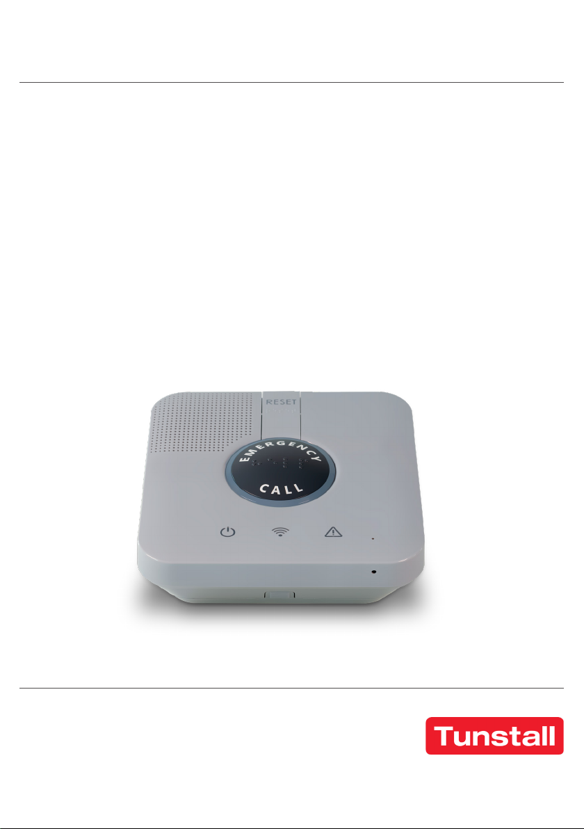
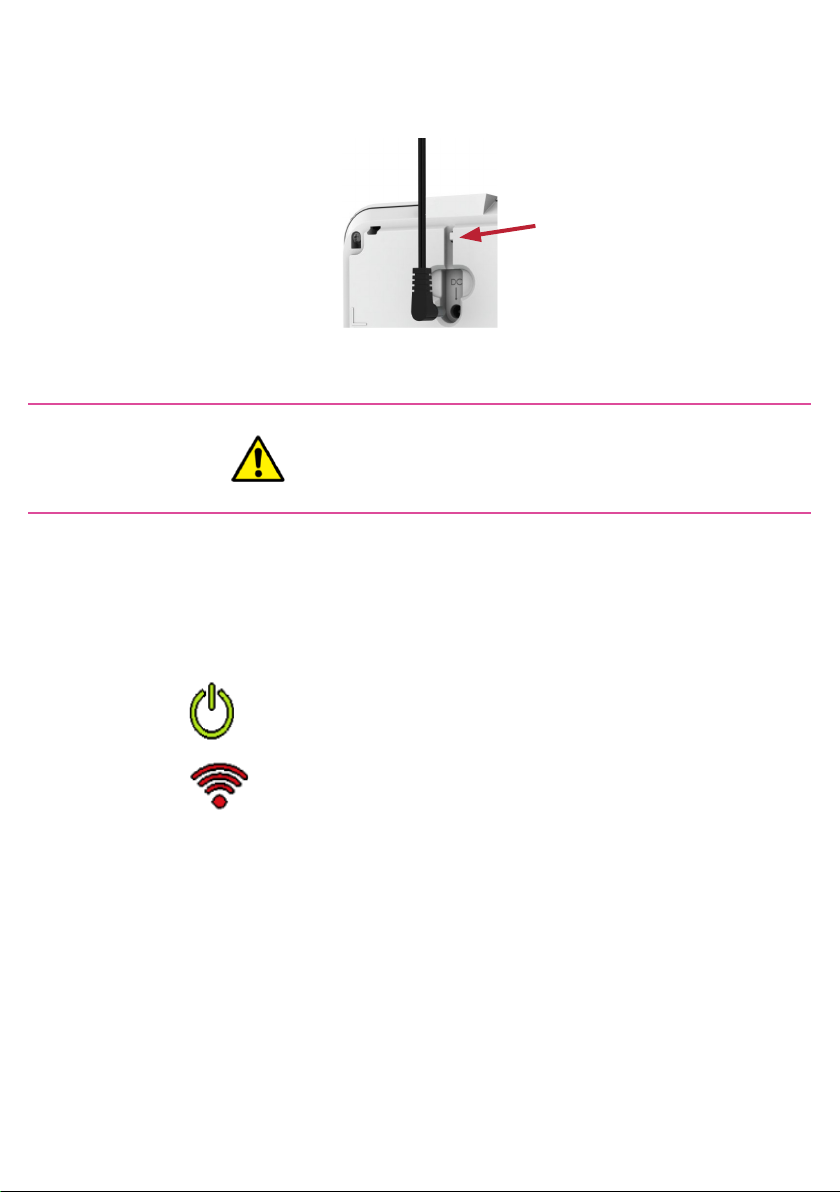
Tunstall Care@Home C7000 Troubleshooting guide

Care@Home™
C7000
User & Installation Guide

Table of Contents
1. Overview 3
2. Installing the C7000 6
2.1. Determining the Best Location for the C7000 6
2.2. Necessary Items 6
2.3. Setting Up the C7000 7
2.4. Wall Mounting the C7000 9
2.5. Configuring C7000 Parameters 10
3. Operating the C7000 10
3.1. Monitoring a Resident – Pro and Family 10
3.2. Emergency Alarms 11
3.3. Safety Alarms 12
3.4. Emergency Conversation Flow with the C7000 12
3.5. C7000 LEDs 13
4. Restoring Factory Settings 14
5. Removing All Peripherals 16
6. Maintaining the C7000 16
6.1. Software Updates 17
6.2. Communications Maintenance 17
6.3. Replacing the Backup Battery 17
6.4. Resetting the C7000 18
7. Specifications 18
Appendix A Testing Peripherals 23
Testing Activity Sensors 23
Testing Emergency Devices 24
Troubleshooting 25
Testing the MDsense 26

page 3 of 32
1. Overview
The C7000 is a connected, emergency-response control device, used for
personal emergency applications.
The C7000 is designed to monitor people living at home or in an
assisted-living facility.
The C7000 works with the Care@Home™ sensor devices, collects
information about the resident’s daily activities, and transmits the
information to the monitoring station.
Note: C7000 is the trade name used
for marketing the Care@Home™
ES7502HC family of control panels.

page 4 of 32
EMERGENCY CALL button:
Initiates an emergency call
Answers ring for
speakerphone call
Disconnects during
speakerphone call Speaker
RESET button:
Cancels an active alarm report
in progress
Clear reminders
Enable/disable activity timer
Activity LED
Power LED Communication LED Trouble LED
PAIRING button
The C7000 includes a high-volume speaker, and a sensitive microphone.
The EMERGENCY CALL and RESET buttons on the C7000, include
raised braille characters, for ease of use by visually impaired residents.

page 5 of 32
Ethernet port (disabled)
Backup battery
Test mode
pinhole
Mini-USB
for service
Power switch
SIM card
Power adapter
The C7000 has a rechargeable battery as a backup power source.
The C7000 communicates with the monitoring station using a cellular
network.
If there is a communications failure, the C7000 saves messages and
sends them when communications are restored.

page 6 of 32
2. Installing the C7000
Installing the C7000 includes the following:
• Determining the best location for the C7000
• Setting up the C7000
• Table placement or wall mounting
• Configuring the C7000 parameters
2.1. Determining the Best Location for the C7000
Survey the premises to determine the best location for the C7000. It is
recommended that you install the C7000 in either the living room or the
master bedroom, in a location:
• Central within the premises
• Strong cellular reception
• Convenient for the resident to access, yet not where the C7000
would attract attention from unauthorized users
• Where the C7000 speakerphone can be heard throughout the
premises
• Away from concrete walls to eliminate radio frequency (RF)
interference
• Away from metal obstructions
• At least 2 m (6 ft.) from the peripheral devices
2.2. Necessary Items
Ensure you have the following:
• Rechargeable backup battery (provided)
• Power adapter (provided)
• SIM card – from the cellular service provider

page 7 of 32
2.3. Setting Up the C7000
To set up the C7000:
1. Ensure the power switch is OFF.
2. Place your thumb in the oval hole above the power switch, and lift off
the back cover.
3. For the cellular model, insert the SIM card, with its contacts facing
downward.
4. Insert the backup battery over the pull strip, such that:
• The printed side of the battery is facing up
• The battery contacts are pointing towards the C7000 contacts
• The end of the pull strip is showing.
Caution: A new battery can cause
damage if it is incorrectly installed.
Battery

page 8 of 32
5. Plug the power cable into the C7000 power socket and secure the
cable under the tab.
6. Connect the cable to power.
7. Replace the back cover
8. Turn on the power switch.
Secure
under tab
Caution: Do not connect to a
socket controlled by a switch
The Power LED lights green.
The Communication LED lights red.

page 9 of 32
2.4. Wall Mounting the C7000
The C7000 can be placed on a tabletop or mounted on a wall with
screws.
To mount the C7000 on a wall:
1. Prepare the following equipment:
• A drill with a standard bit
• Two 3 X 35 DIN 7982 C screws and wall anchors:
• A standard Philips screwdriver
2. Choose a flat, smooth, non-concrete wall.
3. Determine the height at which you want to mount the C7000. This is
usually the eye level of the resident when seated.
4. At the desired height, drill two holes 7.5 cm (2.95 inches) away from
each other horizontally. Ensure that they are level.
5. Screw the screws into the holes, leaving a space of a few millimeters
between the wall and the screw heads.
6. Remove the back cover of the C7000.
7. Align the screw mount holes on the back cover of the C7000 over the
screw heads.
8. Slide the back cover down gently until the screws lock in place.
9. Reattach the C7000 to the back cover.

page 10 of 32
2.5. Configuring C7000 Parameters
The C7000 is pre-configured to manage and control the C7000 and its
associated peripherals.
Use Care@Home™ CMS to adjust the configuration for the requirements
of the resident and the resident’s family. Refer to ESUG05074 Care@
Home CMS Reference Manual.
Some adjustments can made to multiple C7000s using Care@Home™
CareView. Refer to ESUGSC181 CareView User Guide.
3. Operating the C7000
The C7000 communicates with the peripherals to monitor a resident’s
activity, triggers emergency and safety alarms, and acts as a
speakerphone, enabling emergency conversations and remote call-in.
3.1. Monitoring a Resident – Pro and Family
The Pro and Family solutions use the Care@Home™ app and Care@
Home™ web application to monitor and analyze a resident’s activities
based on data collected by the peripherals. Refer to ESUG05050 Care@
Home Caregiver User Guide.
Note: To receive power fail
notifications, the CMS Mains Failure
C7000 parameter must be enabled.

page 11 of 32
3.2. Emergency Alarms
To trigger an emergency alarm, the resident presses the EMERGENCY
button on the C7000 or uses one of the following peripherals.
Device Description Emergency Trigger
Emergency Pendant
Advanced (ES700EPA) Pendant with
panic button and
fall detection
Resident presses panic
button
EPA detects fall
Emergency Pendant
Advanced Jewelry
(ES700EPAJ)
Emergency Pendant
(ES700EP)
Panic button
worn as pendant
or on the wrist
Resident presses panic
button
Emergency Pendant
Plus (ES700EPP)
Emergency Pendant
Plus Jewelry
(ES700EPPJ)
Emergency Pendant
Advanced - BC
(ES700EPA – BC)
Stationary Panic
Detector (ES700SPD)
Stationary panic
button with
optional pull
cord
Resident presses panic
button
Resident pulls out cord
In response to an emergency alarm, the C7000 communicates with the
monitoring station.

page 12 of 32
3.3. Safety Alarms
The C7000 sounds an alarm when peripherals indicate an emergency.
These include:
• Flood detector senses water
• Smoke detector detects smoke
3.4. Emergency Conversation Flow with the C7000
The C7000 supports the following types of conversation flow:
• Half-Duplex: only one party can speak at a time. In this mode, keypad
control is supported. Refer to Half-Duplex Conversation Flow on
page 16.
• Full-Duplex: both parties can hear and speak at the same time. The
call center operator can use telephone keypad numbers 1 or 3 (or as
otherwise configured) to switch to half-duplex.
Note: To configure the keypad assignments, or the
conversation mode parameter, refer to the ESUG05074
Care@Home CMS Reference Manual. Conversation
mode can also be configured for multiple C7000s
using Care@Home™ CareView, Refer to ESUGSC181
CareView User Guide.

page 13 of 32
3.5. C7000 LEDs
The LEDs on the C7000 display operational information, as described in
the following table.
LED Display Description
Power Green
• Lit – AC power connected
• Blinking – Battery operation
• Off – No power
Communication Green
• Lit – Communication
available
• Blinking – Active
transmission
Red
• Lit – Communications failure:
– Cellular version: no SIM
card, loss of cellular
network, or GSM
connectivity test failed
– PSTN version: PSTN line
unavailable
– Cellular/Ethernet version:
Both channels unavailable
– PSTN/Ethernet version:
Both channels unavailable
• Blinking – Blocked
transmission
Orange • Lit – Active conversation
RESET Orange
• Lit (for three seconds) –
Button pressed
• Flashing - Vocal reminder

page 14 of 32
LED Display Description
Trouble Red
• Lit and C7000 beeps
– C7000 or peripheral
malfunction, or lost
communications with the
monitoring station
• Blinking and C7000 beeps –
Peripheral supervision lost or
low battery power
NOTE: To stop the beeps, press
RESET
Activity Blue ring
• Lit – Activity timer is on
• Off – Activity timer is off
• Blinking – Activity timer
expires in less than 15
minutes
EMERGENCY
CALL Red
• Blinking – Alert in progress
• Lit – Message acknowledged
Combination of
LEDs
• Half-duplex call. C7000
microphone active, speaker
inactive.
– Communication - Lit
orange
– RESET - Lit orange
– Trouble - Lit red
– Activity Timer - Lit blue

page 15 of 32
4. Restoring Factory Settings
Restoring the C7000 to factory settings:
• Removes all peripherals
• Resets all parameters to factory defaults
To restore factory settings:
1. Press and hold the RESET button.
2. While holding the RESET button:
a. Insert a probe or the open end of a paperclip into the C7000’s TEST
pinhole.
b. Press the button inside the TEST pinhole and hold for five seconds.
RESET button
TEST button
Caution: Consult with Essence
Smart Care technical support
before restoring factory settings.

page 16 of 32
The C7000 LEDs flash and the C7000 beeps three times. The C7000 is
restored to factory settings.
5. Removing All Peripherals
The monitoring station continues to receive updates about lost
peripherals until they are removed from the C7000.
To remove all the peripherals from the C7000:
1. Press the PAIRING button, and hold for five seconds.
2. Press the RESET button, and hold for five seconds. A voice message
from the C7000 instructs you to press the PAIRING button to remove
all peripherals.
3. Press the PAIRING button. A voice message from the C7000 confirms
that all devices were removed from the C7000.
6. Maintaining the C7000
C7000 maintenance includes:
• Software updates
• Communications maintenance
• Backup battery replacement
• Resetting the C7000
Note: This action removes all peripherals
from the C7000. You need to pair all the
peripherals with the C7000 again.

page 17 of 32
6.1. Software Updates
To perform software and firmware updates for the C7000 and its
peripherals, use the remote boot function in Care@Home™ CMS. Refer
to ESUG05074 Care@Home CMS Reference Manual.
Updates for multiple C7000s can be performed using Care@Home
CareView. Refer to ESUGSC181 CareView User Guide.
After a firmware update, reset the C7000. Refer to 6.4 Resetting the
C7000. Care@Home CareView can be used to restart multiple C7000s.
Refer to ESUGSC181 CareView User Guide.
6.2. Communications Maintenance
If the C7000 uses cellular communications and the quality of the
connection becomes unreliable, consult the cellular service provider to
replace your SIM card or repair the connection.
After replacing the SIM card, reset the C7000. Refer to 6.4 Resetting the
C7000.
6.3. Replacing the Backup Battery
The backup battery is charged automatically when installed in the C7000
and the C7000 is connected to AC power. The battery lasts for up to
three years.
When the C7000 reports low battery for the C7000, replace the backup
battery.
Caution: A new battery can cause damage if it is
incorrectly installed. Be careful to replace the battery
only with the same or equivalent type recommended by
the manufacturer. Discard used batteries responsibly.

page 18 of 32
6.4. Resetting the C7000
Resetting prepares the C7000 for use after maintenance. For example,
firmware updates.
To reset the C7000:
1. Turn the power switch OFF.
2. Remove the back cover.
3. Disconnect the power cable.
4. Remove the backup battery.
5. Wait 20 seconds.
6. Replace the backup battery.
7. Connect the power cable.
8. Replace the back cover.
9. Turn the power switch ON. The power LED lights green.
7. Specifications
The following table lists the C7000 technical specifications.
Item Data
Part Number ES7502HC
Weight 1.23 lb. (0.56 kg), including adapt-
er and battery
Dimensions (H x W x D) 152 x 152 x 71 mm (6 x 6 x 2.8 in.)
Main Power 100-240 VAC, 50/60 Hz, 500 mA
Note: During a reset, the C7000 does not
communicate with the server or peripherals.

page 19 of 32
Item Data
Backup Battery
Standard Double Capacity Battery:
• One Li-Po, 3.7 V, 2800 mAh
• Rechargeable with three-year
battery life
• Provides a minimum of 48
hours of continuous operation
Reporting Modes
Cellular models:
• SIA IP
• DC – 09
• SCAIP
• BS8521:2009
Frequency
• FSK modulation:
– 916.5 MHz (North America
and Australia)
• Bluetooth LE
Communication Channels
Messages are sent and received
using the cellular communication
channel. In the event of a
communication failure, the C7000
automatically stores messages to
send as soon as a connection is
restored.
Color White and gray
Peripheral Devices Up to 30 peripheral devices
Operating temperature 0°C - 49°C (32°F - 120°F)

page 20 of 32
Item Data
Compliance
CE, FCC, IC
ETL :
• UL 1637
• UL 1635
• CSA 22.2 #205
EN 60950-1
EN 301 489-1 & EN 301 489-3
EN 300 220-1 & EN 300 220-2;
Receiver sensitivity: -108 dBm
EN 50130-4
EN 50130-5 Environmental Class I
EN 50134-2, EN 50134-3, and
50134-5
EN 50136-2:2013 Category C
(D3,M3,T1,A1,S0,I0)
Operation
Mode-Pass-Through
Cellular model: AT&T and
PTCRB compliance
EN910-EUR – Compliant with
Global Connection (GCF) require-
ments, as well as the Global Sys-
tem for mobile communications
standard EN 301 511.
Table of contents
Other Tunstall Personal Care Product manuals

Tunstall
Tunstall Lifeline Digital User manual

Tunstall
Tunstall GO User manual

Tunstall
Tunstall SmartLink Medi Guardian MKII 4G Troubleshooting guide

Tunstall
Tunstall iVi User manual

Tunstall
Tunstall Lifeline Vi Installation guide

Tunstall
Tunstall Liberty 300 User manual

Tunstall
Tunstall Lifeline Digital User manual

Tunstall
Tunstall Vi User manual

Tunstall
Tunstall liberty300 Troubleshooting guide

Tunstall
Tunstall Lifeline Digital User manual